ISSN: 1992-8645 www.jatit.org E-ISSN: 1817-3195
1869
AN ADAPTIVE RECOVERY ALGORITHM
FOR LOW LIGHTING IMAGE
1WEI GUO, 2XUEYANG FU, 3QIN LIN, 4XINGHAO DING, 5YUE HUANG
123Department of Communication Engineering, Xiamen University, Fujian, China
4
Prof., Department of Communication Engineering, Xiamen University, Fujian, China
5Assistant. Prof., Department of Communication Engineering, Xiamen University, Fujian, China
E-mail: [email protected], [email protected]
ABSTRACT
In this paper, an efficient and effective adaptive recovery algorithm is presented for low lighting image. Firstly, a multiple point light sources atmospheric scattering mode is proposed based on analyzing the form of light sources, the propagation process of light beam and the influence of multiple light sources. And then, a novel image prior - bright channel prior, which is based on a kind of statistics of the normal illumination images, is also considered in the model. The satisfied results have demonstrated that compared with existing methods, the proposed method has the stronger ability of restoring the low lighting image adaptively.
Keywords: Low Lighting, Multipoint Light Sources, Bright Channel, Image Restoration
1. INTRODUCTION
Low lighting image is a kind of degraded image which is acquired in the night as well as illumination weaker conditions. And the scene is difficult to be discovered because the ambient light is insufficient.
However, low lighting recovery is highly required in computer vision applications and pattern recognition. Firstly, improving the visibility of the low lighting image is acquired by these outdoor computer vision system users. Secondly, the robustness is demanded in some computer recognition algorithms.
In this paper, we present a multiple point light sources atmospheric scattering mode, analyzing the form of light sources [1][2], the propagation process of light beam [3][4] and the influence of multiple light sources [5][6]. While we propose a novel but effective image prior - bright channel prior - based on a kind of statistics that most local regions of the normal illumination images contain some pixels whose intensity are very high in at least one color channel especially in the colored objects.
At last, based on the prior with the presented multiple point light sources atmospheric scattering model and the dark channel prior [7], we can estimate adaptively the noise light image for the first time and the illumination image, and then
restore a high quality recovered image (Figure 1). Our algorithm has valid theoretical basis and overcome the above-mentioned shortcomings that complex processing, color distortion and blocking artifacts.
Section 2 presents the related work in the field of low lighting recovery. In section 3, proposed algorithm is detailed described. Section 4 presents a series of contrast experiments and result analysis. Section 5 gives a conclusion and future work.
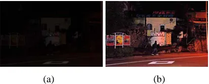
[image:1.612.315.521.507.590.2]
(a) (b)
Figure 1. Low Lighting Adaptive Recovery From A Single Image. (A) Original Low Lighting Image. (B) Image After
Recovery By Proposed Algorithm.
2. RELATED WORK
ISSN: 1992-8645 www.jatit.org E-ISSN: 1817-3195
1870 But the image colors tend to be desaturated, even grayish due to global.
The other is image reversion. X. Dong [13] from Tsinghua University observe that the inverted low lighting image is much too similar with the haze image, so applying a de-haze algorithm on the inverted image, and then they reverse the de-hazed image back. But there is no theory to support this approach and it prone to blocking artifacts.
3. LOW LIGHTING IMAGE ADAPTIVE
RECOVERY ALGORITHM
[image:2.612.87.304.380.627.2]By analyzing the form of light sources, the propagation process of light beam and the influence of multiple light sources, we present a multiple point light sources atmospheric scattering mode. While we propose a novel but effective image prior - bright channel prior, which is based on a kind of statistics of the normal illumination images. At last, based the model, the bright channel prior and the dark channel prior, we can recover adaptively the low lighting image.
Table I. Notation Used In This Paper
p
,v
,i
s
Subscripts for surface point, viewer, the i-th source
β
Atmospheric attenuation coefficientI
Observed intensityR
Ideal illumination imagex
Distance along the ray from viewer(integration variable)
i
d
Distance of single scattering from the i-thpoint light source
i
A
Radiant intensity of the i-th point lightsource
pv
D
Distance between surface point, vieweri
s v
D
Distance between the i-th point lightsource, viewer
3.1 Multiple Point Light Sources Atmospheric Scattering Model
We present the viewer received radiance
I
, which is constituted by the three parts - the direct attenuation from the surface pointL
p,v, the direct attenuation from these multiple point light sources,
i
s v
L
and the airlight for the viewerL
a,v . The model can be expressed as:, i, ,
p v s v a v
I
=
L
+
L
+
L
(1)where the notation used are indicated in TABLE I.
Firstly, modulated by the reflectance of surface
R
, the input - the radiance at the surface pointL
p is transformed into the output - thereflected radiance
R
⋅
L
p. And then the reflected radiance is attenuated with the distance between the surface point and the viewer,, 2 pv D p p v pv
R L
e
L
D
β −
⋅
⋅
=
(2)Secondly, the direct attenuation from these multiple point light sources ,
i
s v
L
attenuate the radiance of these multiple point light sources with the distance between the point light source and the viewer respectively,, 2
s vi
i i D i s v s v
A e
L
D
β −⋅
=
∑
(3)Thirdly, the airlight for the viewer
L
a,v is caused by the scattering of the radiance from these multiple point light sources1 i
s
+ , which include the surface point.1
1
, 0 2
1 i pv d D x i a v i
A
e
L
e
dx
d
β ββ
+ − − + +⋅
=
∑∫
⋅ ⋅
(4)According to the above analysis, we present the final form of the multiple point light sources atmospheric scattering model,
1
1
2 2 0 2
1
pv s vi i
pv
i
D D D d
p i i x
pv s v i
R L e A e A e
I e dx
D D d
β β β
β β + − − − − + + ⋅ ⋅ ⋅ ⋅ = +
∑
+∑∫
⋅ ⋅ (5) However, this is an ill-posed problem with some unknown. So let us define:1 2 pv D p pv
L
e
E
D
β −⋅
=
(6)ISSN: 1992-8645 www.jatit.org E-ISSN: 1817-3195
1871
1
1
2 2 0 2
1
s vi i
pv
i
D d
D x
i i
s v i
A e
A
e
E
e
dx
D
d
β β
β
β
+
− −
− +
+
⋅
⋅
=
∑
+
∑∫
⋅ ⋅
(7)which is the noise light image leading to the shift of the scene color.
Therefore, the multiple point light sources atmospheric scattering model can be simplified as:
2 1
E
E
R
I
=
⋅
+
(8)3.2 Bright Channel Prior
We propose a novel but useful prior - bright channel prior - that is based on the observation on outdoor normal illumination during the day images, except for the shadow and dark area: at least one color channel of some pixels whose intensity is very high and close to 1 in most of small patches. In other words, after two maximum filtering, the biggest intensity of these pixels in every patch of the outdoor normal illumination image is close to 1. So we define the concept of a bright channel to describe the observation. The bright channel can be expressed as:
))
(
max
(
max
)
(
} , , { )
(
R
y
x
R
cb g r c x y bright
∈ Ω ∈
=
(9)where
c
is the color channel ofR
,Ω
(
x
)
is a local patch centered atx
. The position of these maximum operators can be swapped. In order to hold more edge information, we use the Guided Filter [14] to refine the bright channel and the dark channel maps.With the bright channel prior, except for the extensive shadow and dark area, the intensity of the outdoor normal illumination image
R
’s bright channel is close to 1:1
)
(
x
→
R
bright (10)There are four facts causing the high intensity in the bright channel: a) light sources, whose reflectance can be seen as one; b) color objects, for instance, green leaves, red flowers, blue water, whose intensity of any color channel is high; d) bright objects, e.g. white cars and wall; e) high reflection objects, such as mirror. Because the natural outdoor normal illumination images are usually colorful and include bright objects, the bright channel is does exist.
To further demonstrate the bright channel presents widely in the normal illumination images, we collect a great number of outdoor images from the internet including city, streets, buildings,
flowers and trees, and so on. After two maximum filtering using a patch size 15
×
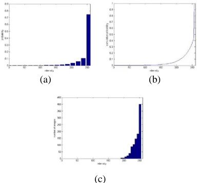
15, these color images and their bright channels are showed in Figure 2. Further more, we randomly select 1,000 images and cut out the large shadow region, and then calculate the intensity histogram over all of the 1,000 bright channels, at last the results are showed in Figure 3.
[image:3.612.320.516.190.467.2]
Figure 2. Left: Normal Illumination Images In Our Database. Right: The Corresponding Bright Channel.
(a) (b)
(c)
Figure 3. Statistics Of The Bright Channel. (A) Histogram Of The Intensity Of The Pixels In All Of The 1,000 Bright Channels. (B) Cumulative Distribution. (C)
[image:3.612.320.512.495.673.2]ISSN: 1992-8645 www.jatit.org E-ISSN: 1817-3195
1872 From the Figure 2, we find that the intensity of the whole image becomes very high and most of them are close to 1, after two maximum filtering. Therefore, the phenomenon conforms to the bright channel prior. Figure 3 (a) is the intensity histogram over all of the 1,000 bright channels. Figure 3 (b) is the corresponding cumulative distribution. We can find that in the bright channel the intensity of about 85% of the pixels is over 225, and the intensity of about 70% of the pixels is over 240. And Figure 3 (c) is the average intensity of each bright channel and plot the corresponding histogram. It is obvious that the intensity of most bright channel pixels is very high, and only a little is out of the prior. So the statistic proves the bright channel prior is logical.
3.3 Adaptive Recovery
Firstly, we estimate the noise light image. Based on the dark channel prior, we can adaptively estimate the noise light image by putting minimum operators on both sides of (8):
2 } , , { ) ( 1 ) , , ( )
(
(
min
(
))
min
(
min
(
))
min
I
y
E
R
cy
E
b g r c x y c b g r c x
y∈Ω ∈
=
⋅
∈Ω ∈+
(11)
where
E
1 is assumed to be smooth in a local patch)
(
x
Ω
.As
R
is an ideal illumination image, the dark channel ofR
is close to zero due to the dark channel prior:
(
)
min
(
min
(
))
0
} , , { ) (
=
=
∈ Ω∈
R
y
x
R
c b g r c x y dark (12)Putting (12) into (11), we can adaptively estimate the noise light image by:
2
min ( min
( ) ( , , )( ))
c y x c r g b
E
ω
I
y
∈Ω ∈
= ⋅
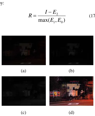
(13)In order to adjust the tone of the restored image, we retain a portion of noise light and introduce a constant parameter
ω
(ω
=
0
.
5
) into (13). The noise light image is shown in Figure 5 (b).Secondly, we estimate the illumination image. With the above noise light image, we can adaptively calculate the illumination image based on the bright channel prior. We put maximum operators on both side of (8):
2 } , , { ) ( 1 ) , , ( )
(
(
max
(
))
max
(
max
(
))
max
I
y
E
R
cy
E
b g r c x y c b g r c x
y∈Ω ∈
=
⋅
∈Ω ∈+
(14)
The bright channel of
R
is close to 1 due to the bright channel prior:1
))
(
max
(
max
)
(
} , , { ) (=
=
∈ Ω∈
R
y
x
R
c b g r c x y bright (15)Putting (13) and (15) into (14), we can adaptively estimate the illumination image by:
))
(
min
(
min
))
(
max
(
max
) , , ( ) ( ) , , ( ) (1
I
y
I
y
E
c b g r c x y c b g r c xy∈Ω ∈
−
⋅
∈Ω ∈=
ω
(16)The illumination image is shown in Figure 4 (c).
Thirdly, with the above adaptive noise light image and illumination image, we recover the scene radiance. Because the value of the illumination is close to zero, the noise contribution can dominate the restored scene. So we also restrict the illumination by a lower bound
E
0 (E
0=
0
.
1
).The final scene radiance (Figure 4 (d)) is recovered by:
)
,
max(
1 02
E
E
E
I
R
=
−
(17)
(a) (b)
(c) (d)
Figure 4. (A) Original Low Lighting Image. (B) The Noise Light Image. (C) The Illumination Image. (D)
Image After Recovery By Proposed Algorithm.
4. EXPERIMENT AND RESULT ANALYSIS
In order to proving our proposed algorithm’s advantage, proposed algorithm is compared with MSRCR [10] and X. Dong [13]. And we evaluate the recovery image with the method of subjective evaluation and objective evaluation - the contrast promotion index, the image definition and the information entropy.
[image:4.612.317.518.287.531.2]ISSN: 1992-8645 www.jatit.org E-ISSN: 1817-3195
1873 of the restored image desaturated seriously and grayish due to global. Although the method of X. Dong upgrades the local contrast, it produces the blocking artifacts and loses a portion of color information. Our method highlights the details of low lighting image, recovers the color of the image, upgrades the local contrast and avoids the blocking artifacts.
(a) (b)
[image:5.612.319.518.76.346.2]
(c) (d)
Figure 5. Enhancing Images Using Different Methods. (A) Low Lighting Image. (B) The Result Of MSRCR [10].
(C) The Result Of X. Dong [13]. (D) Our Result.
(a) (b)
(c) (d)
Figure 6. Enhancing Images Using Different Methods. (A) Low Lighting Image. (B) The Result Of MSRCR [10].
(C) The Result Of X. Dong [13]. (D) Our Result.
(a) (b)
[image:5.612.96.294.192.388.2]
(c) (d)
Figure 7. Enhancing Images Using Different Methods. (A) Low Lighting Image. (B) The Result Of MSRCR [10].
(C) The Result Of X. Dong [13]. (D) Our Result.
(a) (b)
(c) (d)
Figure 8. Enhancing Images Using Different Methods. (A) Low Lighting Image. (B) The Result Of MSRCR [10].
(C) The Result Of X. Dong [13]. (D) Our Result.
[image:5.612.321.516.402.651.2] [image:5.612.97.292.424.663.2]ISSN: 1992-8645 www.jatit.org E-ISSN: 1817-3195
1874 biggest in all of these methods, so the recovery image is clearer and include more information.
Table Ii The Contrast Index (Ci) Comparison Of All Methods
CI Original MSRCR
[10]
X. Dong [13]
Our result
Figure 6 60.56 56.89 77.86 89.20
Figure 7 11.09 22.19 35.89 59.69
Figure 8 45.57 38.92 52.96 64.35
Figure 9 52.26 34.01 55.09 73.87
Table Iii The Clarity (Cl) Comparison Of All Methods
CL Original MSRCR
[10]
X. Dong [13]
Our result
Figure 6 39.19 69.55 78.72 101.25
Figure 7 21.18 44.37 94.36 132.78
Figure 8 22.63 49.69 85.72 92.43
Figure 9 28.55 29.91 80.70 92.85
Table IV The Information Entropy (IE) Comparison Of All Methods
IE Original MSRCR
[10]
X. Dong [13]
Our result
Figure 6 8.64 8.54 8.74 8.31
Figure 7 6.90 8.00 8.71 9.21
Figure 8 6.66 8.53 8.86 8.91
Figure 9 8.19 8.63 9.25 9.48
5. CONCLUSION AND FUTURE WORK
In this paper, by analyzing the form of light sources, the propagation process of light beam and the influence of multiple light sources, we have presented a multiple point light sources atmospheric scattering mode. Afterwards, we put forward a novel image prior - bright channel prior for image recovery according to statistics of normal illumination images. Combining these priors with the multiple point light sources atmospheric scattering mode, we can restore low lighting images effectively. Finally, compared with existing methods in the view of objective and subjective, the proposed method has the stronger ability of restoring the low lighting image adaptively.
For future work, on the one hand, making use of the multiple point light sources atmospheric scattering mode, we hope to recover the haze images. On the other hand, although refined with the Guided Filter, the bright channel map and the dark channel map are still not enough fine. So we intend to find a better way to refine them.
ACKNOWLEDGMENT
The work is supported by the National Natural Science Funding of China, NO. 61172179, 30900328, the Fundamental Research Funds for the Central Universities 2011121051, and the Natural Science Foundation of Fujian Province of China 2012J05160.
REFRENCES:
[1] S. G. Narasimhan and S. K. Nayar, “ Chromatic framework for vision in bad weather”, Proc. IEEE Conf. Computer Vision and Pattern Recognition, Vol. 1, 2000, pp. 598-605.
[2] S. G. Narasimhan and S. K. Nayar, “Vision and the atmosphere”, Int’l Journal of Computer Vision, Vol. 48, 2002, pp. 233-254.
[3] H. Koschmieder, “Theorie der horizontalen sichtweite”, Beitr. Phys. Freien Atm., Vol. 12, 1924, pp. 171-181.
[4] F. Cozman and E. Krotkov. “Depth from scattering”, In Proceedings of the 1997 Conference on Computer Vision and Pattern Recognition, Vol. 31, 1997, pp. 801-806. [5] B. Sun, R. Ramamoorthi, S. Narasimhan, and
S. Nayar, “A practical analytic single scattering model for real time rendering”, ACM TOG, 2005, 24: 1040-1049.
[6] Arjan Gijsenij, Rui Lu and Theo Gevers, “Color Constancy for Multiple Light Sources”, IEEE Transactions on Image Processing, Vol. 21, No. 2, February 2012.
[7] K. He, J. Sun, and X. Tang, “Single image haze removal using dark channel prior”, Proc. IEEE Conf. Computer Vision and Pattern Recognition, 2009, pp. 1956-1963.
[8] E. Land, “An alternative technique for the computation of the designator in the retinex theory of color vision”, Proc. Nat. Acad. Sci. USA, Vol. 83, No. 10, May 1986, pp. 3078-3080.
ISSN: 1992-8645 www.jatit.org E-ISSN: 1817-3195
1875 Conference on Image Processing, 1996, pp. 1003-1006.
[10] Daniel J. Jobson, Zia ur Rahman, and Glenn A. Woodell, “A multiscale retinex for bridging the gap between color images and the human observation of scenes”, IEEE Transactions on Image Processing, Vol. 6, No. 7, 1997, pp. 965-976.
[11] D. Jobson, Z. Rahman, and G. Woodell, “Properties and performance of a center/surround retinex”, IEEE Transactions on Image Processing, Vol. 6, No. 3, Mar 1997, pp. 451-462.
[12] Laurence Meylan, David Alleysson, and Sabine Susstrunk, “Model of retinal local adaptation for the tone mapping of color filter array images”, J. Opt. Soc. Amer. A, Vol. 24, No. 9, Sep 2007, pp. 2807-2816.
[13] X. Dong, Y. Pang, and J.-T Wen, “Fast efficient algorithm for enhancement of low lighting video”, Proc. of SIGGRAPH, Los Angeles, California, 2010.
![Figure 7. Enhancing Images Using Different Methods. (A) Low Lighting Image. (B) The Result Of MSRCR [10]](https://thumb-us.123doks.com/thumbv2/123dok_us/8916204.961938/5.612.321.516.402.651/figure-enhancing-images-using-different-methods-lighting-result.webp)
