ORIGINAL RESEARCH ARTICLE
ANALYSIS OF ALTERNATIVE CURRENT FIELD DETECTION SIGNALS BASED ON COMPLEX
SURFACE DEFECTS
*Jing-lin WANG, Shang-kun REN, Xian-zhi REN and Qing-quan FAN
Key Laboratory of Nondestructive Testing of Ministry of Education, Nanchang Hang-kong University,
Nanchang 330063, China
ARTICLE INFO ABSTRACT
Alternating Current Filed Measurement (ACFM) and Alternating Current Magnetic Flux Leakage (AC-MFL) method have been widely used in engineering practice. They both use U-shaped yoke probes and are basically the same in the probe and signal processing. In actual inspection, the shape of the defect is usually complicated, and a single defect or several defects may occur at the same time. Multiple defects may appear as cross-shaped cross cracks, round-hole defects, and parallel cracks. In view of the emergence of such complex defects, the effects of cross-type cross cracks, round-hole defects, parallel cracks and ACFM and AC-MFL detection signals are studied. The experimental results show that the different crack shapes and detection signals have different characteristics, and the complex defect pairs can be comprehensively evaluated according to different defect signal characteristics. The research results are of great significance for the detection and evaluation of metal surface defects.
Copyright © 2019,Jing-lin WANG. This is an open access article distributed under the Creative Commons Attribution License, which permits unrestricted use, distribution, and reproduction in any medium, provided the original work is properly cited.
INTRODUCTION
Current Field Measurement (ACFM) and Alternative Current Magnetic Flux Leakage (AC-MFL) are two non-destructive testing methods that have emerged in recent years. Both methods have the advantages of high detection sensitivity, miniaturization of probes, and ease of automation, which have attracted the scholars’ attention [LI. W. 2007]. At present, the two detection technologies have corresponding equipment in actual engineering inspection. The detection techniques of the two are basically the same in the probe and signal processing, except that the direction of the probe scanning is just the opposite. For the ACFM technology, when the connection between the two legs of the U-shaped yoke probe is parallel with the crack, the detection sensitivity is the highest. The AC-MFL technology has the highest detection sensitivity when the U-shaped yoke probe has a two-pin connection perpendicular to the crack. In the process of actually detecting the work-piece, the surface is usually covered with the protection of the anti-corrosion coating or the insulation layer structure [H.ROWSHANDELA 2018].
*Corresponding author: Jing-lin WANG
Key Laboratory of Nondestructive Testing of Ministry of Education, Nanchang Hang-kong University, Nanchang 330063, China
The direction of the crack is unknown. Before the grinding, the internal condition of the component is unknown beforehand, and the defect shape and electromagnetic field signal are unknown. It is a nonlinear relationship. The detection signal is greatly affected by the shape of the crack. The traditional magnetic particle detection technology is too slow to detect and is not conducive to detection. Therefore, studying the relationship between ACFM and AC-MFL signals and complex crack characteristics is of great significance for the evaluation and quantitative evaluation of surface defects of metal specimens [ LI .W, X A.YUAN 2014].
ACFM and AC-MFL detection principle analysis
ACFM is an emerging non-destructive testing technology developed on the basis of eddy current and magnetic flux leakage detection [X C.HU , F L.LUO 2011]. The principle of ACFM technology is that the excitation probe induces a uniform alternating current on the surface of the work-piece which needs to be inspected. When scanning, the two-legged connection of the U-shaped yoke probe is parallel to the crack direction, and the scanning direction is also parallel with the crack. When there is no defect in the work-piece or away from
ISSN: 2230-9926
International Journal of Development Research
Vol. 09, Issue, 01, pp.25315-25320, January, 2019
Article History:
Received 10th October, 2018 Received in revised form 19th November, 2018 Accepted 23rd December, 2018 Published online 30th January, 2019
Available online at http://www.journalijdr.com
Key Words:
ACFM; AC-FML; Complex defect;
Defect signal characteristics.
Citation: Jing-lin WANG, Shang-kun REN, Xian-zhi REN and Qing-quan FAN. 2019. “Analysis of alternative current field detection signals based on complex
surface defects”, International Journal of Development Research, 09, (01), 25315-25320.
the defect, the induced current on the surface of the work-piece is evenly distributed; when the induced current flows through the defect area, the current bypasses from both sides and the bottom of the crack, causing disturbance of the surface induced current magnetic field, and the sensing probe collects the defect above the sensing. The magnetic field distortion information is processed and analyzed, and the size information describing the defect state can be obtained. The schematic diagram of the detection principle is shown in Figure.1 [K.SONG ,C.CHEN 2012].
Figure 1. ACFM Detection schematic
According to the theoretical analysis of ACFM detection, the detection magnetic field of the defect part has three components, and the directions are: x-direction parallel to the crack direction in the surface, and y-direction perpendicular to the crack direction in the surface and the surface of the work-piece. Vertically marked as z direction [W .LI ,X A .YUAN 2015]. When the probe scans the surface of the defect-free piece, the induced current on the surface of the work-piece is evenly distributed parallel to the y direction, and the magnetic components of By and Bz are 0. When the probe scans the surface crack of the work-piece in parallel, the probe exhibits a pair of characteristic extreme value signals with opposite polarities on the Bz component at the two positions just entering the crack and leaving the crack. When the probe enters the crack region, Bx component signal will drop at first and then rise, displaying a wide depression. Since the By component is parallel to the direction of the induced current, the change is weak and is not considered. In the detection, only the Bx and Bz are subjected to signal analysis processing to obtain the size information describing the crack state, and the
detection purpose is achieved[ M L.FENG ,Y P.CAI 2012].
AC-MFL technology and ACFM technology have great differences in detection mechanism. AC-MFL technology is a technology based on leakage magnetic field detection. DC magnetic flux leakage detection (DC-MFL) can also be regarded as the former in the magnetization field frequency. Zero time (constant magnetic field) [D H .WU, D H.YOU 2014]. The detecting sensor also uses a U-shaped yoke, and a magnetizer is formed on the yoke by winding the exciting coil, and the scanning direction of the U-shaped yoke is perpendicular to the crack. When the magnetizing coil is excited by the sinusoidal signal, a corresponding alternating magnetization field is generated in the yoke, and a magnetic circuit is formed with the member to be inspected, which is affected by the skin effect, and the alternating field is substantially present on the surface layer of the member and
[image:2.595.39.287.182.346.2]saturates the magnetization. When there is no defect, the magnetic lines of force are all bound in the skin layer of the tube wall to make it saturated. When the defect exists, the AC leakage magnetic field is formed, and the frequency is the same as the AC excitation frequency. The detection coil or the Hall sensor is located between the two legs, and the vertical component and the horizontal component can be detected to represent the defect detection. The detection mechanism is as shown in Figure. 2, and the defect information can be characterized by using the detection coil to acquire the leakage magnetic field at the defect.
Figure 2. AC-MFL Detection schematic
From the detection principle: the two detection techniques are based on the theory of electromagnetism. Both use U-shaped yoke as the exciter on the probe, but the ACFM method emphasizes the distortion of the induced current magnetic field. The AC-MFL method emphasizes Magnetic field leakage[ J.SHEN . (2017) PhD]. For the AC-MFL test, the detection probe is in the process of scanning, which is opposite to the ACFM scan. The performance of the U-shaped yoke probe is perpendicular to the crack direction. The vertical component of the detected magnetic field of the defect part is consistent with the ACFM vertical component magnetic field signal characteristic, and the detection magnetic field horizontal component Bx of the defect part is opposite to the ACFM detection horizontal component magnetic field signal characteristic, for the DC magnetic flux leakage method. (DC-MFL method), its signal characteristics are consistent with AC-MFL signal characteristics.
Analysis of Alternative Current Field Detection Signals Based on Complex Surface Defects
Detection signal characteristics of cross-shaped crack: The
45# cylindrical steel test block with diameter φ100mm was
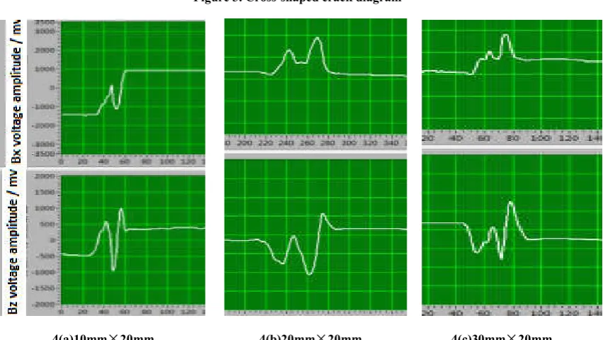
[image:2.595.312.555.195.274.2]direction. When the detection signal is an AC-MFL signal, the detection signal is a superposition of the ACFM signal and the AC-MFL signal for the cross type cross crack. From test result 4(a), when the two-legged connection of the excitation U-shaped yoke probe is parallel to the horizontal direction of the cross-shaped crack (x direction), the crack is scanned for the length of 10 mm and 20 mm. When the probe just enters the crack region, the main performance of the ACFM signal. As the probe moves, when the probe just enters the crack region and leaves the crack region, the Bz magnetic field component signal in the vertical direction will produce a maximum or minimum value, while in the horizontal direction, the Bx magnetic field component will have a very small value. As the probe moves continuously, the AC-MFL signal generated by the crack in the vertical direction is continuously increased.
Therefore, for the Bz magnetic field component in the vertical direction, the ACFM and AC-MFL signals will be
superimposed at the middle of the crack. What’s more, for
the crack in the horizontal direction and the crack in the vertical direction do not occur at the same time, the Bz magnetic field component signal does not appear with a minimum value in the Bz direction but signal peaks of two troughs and one peak when the probe scans the cross-type
crack. For the signal on the Bx component, the distortion
magnetic field component on the Bx component of the ACFM technique has a relatively small influence on the central position of the crack as the probe moves continuously, and the main performance is the leakage of the AC-MFL technique. The magnetic signal, therefore, for the Bx component, will produce an upward characteristic extremum when the probe scans to the middle of the crack. At the same time, when scanning the cross-type crack, as a result of the interaction between ACFM and AC-MFL, the background value will change when the probe scans from the position where the crack starts to the end of the crack. From the test results 4(b) and 4(c), as the length of the crack in the horizontal direction of the cross-shaped cross crack increases, the magnetic field signal on the Bz magnetic field component generates two
[image:3.595.110.492.240.320.2]peaks and two trough characteristic signals, The reason is that as the crack length increases in the horizontal direction, the distorted magnetic field signal generated by the induced current in the ACFM technique is separated from the leakage superimposed region of the magnetic field in the AC-MFL technique, resulting in two peaks and two valley signals of the Bz signal.
Figure 3. Cross-shaped crack diagram
[image:3.595.88.514.338.578.2]
4(a)10mm×20mm 4(b)20mm×20mm 4(c)30mm×20mm
Figure 4. Cross-shaped cross crack test result chart
Figure 5. Schematic diagram of a round hole defect
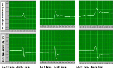
[image:3.595.127.475.617.687.2]Detection signal characteristics of round hole defects: The 45# cylindrical steel test block with the diameter specification
of φ100 was selected as the research object. The round hole
type defect was processed on the 45# cylindrical steel test block. The diameter of the round hole type defect was 1mm, and the depth was 1mm, 2mm, 3mm respectively. The size diagram is shown in Figure.5. The effect of a circular hole type defect with a diameter of 1 mm and a depth varying from 1, 2, and 3 mm on the detection signal was investigated. Repeat the test for the round hole defect shown in Fig. 5, and the test result is shown in Figure.6. The test result of the defect test
with the diameter of φ1mm and the depth of 1mm is 6(a), the
test result of the defect of diameter φ1mm and the depth of
2mm is shown in Figure. 6(b), the diameter is φ1mm, and the
depth is 3mm.
The test results of the defects are shown in Figure 6(c). In the Bz magnetic field component in the vertical direction, the signals of both ACFM and AC-MFL behave the same, and the characteristic signals are also the same. For the signals of the magnetic field components on Bx, the signals of ACFM and AC-MFL are just the opposite. It can be seen from the detection results shown in FIG. 6 that the signal of the circular hole type defect on the Bx magnetic field component is expressed as an AC-MFL signal. This also indicates that the leakage signal exhibited by the magnetic field in the AC-MFL technology that the sensor mainly picks up when detecting the defect of the circular hole type. At the same time, as the depth of the defect of the circular hole type is deepened, the Bx magnetic field signal of the horizontal component picked up
continuously increases, and the Bz magnetic field signal on the vertical component of the pickup does not change significantly. Therefore, the evaluation of the round hole type defect is judged. In the process, the depth of the circular hole can be judged mainly based on the Bx signal.
Detection signal characteristics of two parallel cracks: The
45# cylindrical steel test block with the diameter of φ100mm
was selected as the research object. The parallel cracks with
length, width and depth of cracks of 30×0.5×3mm were
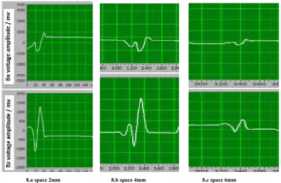
processed on the 45# cylindrical steel test block. The crack spacing is 2mm, 4mm, 6mm, and the parallel crack size is shown in Figure 7. The effect of parallel crack on the detection signal is studied. The parallel crack shown in Figure.7 is repeatedly scanned along the center line.
When the scanning, the two-leg connection of the probe is parallel to the crack direction, and the scanning direction is also parallel with the crack. The test result is shown in Figure. 8. The crack test results of two parallel cracks with a spacing of 2 mm are shown in Figure. 8(a). The test results of cracks with a parallel crack spacing of 4 mm are shown in Figure.
8(b), and the crackswith a distance of 6 mm between the two
parallel cracks are shown. The test results of the defects are shown in Figure 8(c). Figure 8 shows that for parallel cracks, the detection signal is characterized by an ACFM signal. When the two cracks spacing is small, the ACFM signal superimposed by the two cracks is more obvious, and the influence on the picked Bx and Bz magnetic field component signals is greater.
[image:4.595.85.520.239.501.2]
6.aφ1mm,depth 1 mm 6.cφ1mm,depth 2mm 6.bφ1mm,depth 3mm
Figure 6. Round hole type defect test test result chart
[image:4.595.129.480.537.600.2]And detecting the speed at which the probe moves has a greater effect on the signal on the Bx magnetic field component. When the detection speed is slow, the Bx magnetic field component will have two troughs. This is because as the detection speed slows down, the induced current in the x direction is relatively increased from the bottom of the crack center, resulting in induced current. The horizontal component of the induced magnetic field on the surface increases, resulting in an increasing width of the recessed region of Bx. As the distance between the two parallel cracks increases, the superposition effect of the two signals will be weaker and weaker, and the influence of the magnetic field components on the Bx and Bz components will also be weakened. This is due to the increase in the spacing between the parallel cracks, resulting in a decreasing distortion magnetic field signal, and the distortion magnetic field signal picked up by the detection sensor will also be continuously reduced, so that the signals on the Bx and Bz components are continuously reduced.
Conclusion
Cross-shaped cross cracks, round-hole defects, and parallel cracks are common defects that cause fracture failure of components. Different types of defects and different scanning modes will produce different magnetic field signals. The experimental research in this paper has important guiding significance for the evaluation and quantification of metal surface cracks. The test results are as follows:
(1) For the cross type cross crack, the detected signal picked up is a result of the interaction between the distortion magnetic field of the ACFM method and the leakage magnetic field of the AC-MFL method.
(2) For the round hole type defect, the detected signal picked up is mainly the result of the leakage magnetic field in the AC-MFL method.
(3) For parallel cracks, the detected signal picked up is mainly the distortion magnetic field signal in the ACFM method. Moreover, the spacing between the parallel cracks has a great influence on the detection signal, and as the spacing of the parallel cracks increases, the intensity of the detection signal will continuously decrease.
(4) The AC electromagnetic detection signal of complex crack defects is measured by the test, which can provide reference for the quantitative evaluation of AC field detection.
REFERENCES
Feng,M L.Y P.CAI ,C R. SONG . 2012.Influence analysis
of current frequency and lift-off on alternating current field measurement[J].CHINA MEASUREMENT & TEST, 38(1):32-34.
H.ROWSHANDELA, G.L.NICHOLSONA,J.L.SHENB. 2018. Characterisation of clustered cracks using an ACFM sensor and application of an artificial neural network [J].NDT&E International, 04(007):80-88
HU, X C. LUO, F L. HE, Y Z. 2011. Pulsed alternating current field measurement technique for defect identification and
quantification [J]. Journal of Mechanical Engineering,
47(4):7-22.
LI, W. YUAN, X A. G M. 2015. CHEN. Research on In-service Detection for Axial Cracks on Drill Pipe Using the Feed-through Alternating Current Field Measurement [J].
Journal of Mechanical Engineering, 51(12):8-15.
LI. W, X A.YUAN, G M, CHEN. 2014. A feed-through ACFM probe with sensor array for pipe string cracks
inspection [J].NDT&E International, 67:17-23.
LI. W. 2007. Research on ACFM Based Defect Intelligent Recognition and Visualization Technique [D]. QingDao: China University of Petroleum,
[image:5.595.93.502.65.330.2]
8.a space 2mm 8.b space 4mm 8.c space 6mm
Figure 8. Parallel crack test test result chart
SHEN, J. 2017. PhD .Responses of alternating current field measurement (ACFM) to rolling contact fatigue (RCF) cracks in railway rails University of Warwick
SONG , K., CHEN, C., KANG. Y H. 2012. Mechanism study of AC-MFL method using U-shape inducer [J].Chinese
Journal of Scientific Instrument, 33(9):1980-1985.
WU, D H. YOU, D H. LIU. Z L. 2014. Mechanism and experimental research on skin depth in AC magnetic flux
leakage testing [J]. Chinese Journal of Scientific
Instrument, (2):327-336.
![Figure.1 [K.SONG ,C.CHEN 2012].](https://thumb-us.123doks.com/thumbv2/123dok_us/8889544.950058/2.595.39.287.182.346/figure-k-song-c-chen.webp)