(12)
United States Patent
Bennett et al.
(54) PORTABLE FLUID SENSING DEVICE AND METHOD
(75) Inventors: James Bennett, Santa Clara, CA (US); G. Cameron Dales, Saratoga, CA (US); John M. Feland, III, Palo Alto, CA (US); Oleg Kolosov, San Jose, CA (US); Eric Low, Berkeley, CA (US); Leonid Matsiev, San Jose, CA (US); William C. Rust, Mountain View, CA (US); Mikhail Spitkovsky, Sunnyvale, CA (US); Mark Uhrich, Redwood City, CA (US)
(73) Assignee: Visyx Technologies, Inc., SUilllyvale, CA (US)
( *) Notice: Subject to any disclaimer, the term of this patent is extended or adjusted under 35 U.S.C. 154(b) by 0 days.
(21) Appl. No.: 111111,846
(22) Filed: Apr. 20, 2005
(65) Prior Publication Data
US 2006/0031030 Al Feb. 9,2006
Related U.S. Application Data
(60) Provisional application No. 60/564,3 71, filed on Apr. 21,2004.
(51) Int. Cl.
GOlF 25/00 (2006.01)
GOlL 27/00 (2006.01)
GOlN 11/00 (2006.01)
(52) U.S. CI ... 7021100; 702/50
110 500~
111111
1111111111111111111111111111111111111111111111111111111111111
US007272525B2
(10)
Patent No.:
US 7,272,525 B2
Sep.18,2007
(45)
Date of Patent:
(58) Field of Classification Search ... 702/45,
(56)
DE
702/50,100; 73/861.19,861.24
See application file for complete search history.
References Cited
U.S. PATENT DOCUMENTS
5,586,445 A 12/1996 Bessler 5,708,191 A 111998 Greenwood et al. 5,741,961 A 4/1998 Martin et al. 5,886,250 A 3/1999 Greenwood et al. 6,044,694 A 4/2000 Anderson et al. 6,082,180 A 7/2000 Greenwood
(Continued)
FOREIGN PATENT DOCUMENTS
100 50 299 Al 4/2002
(Continued)
OTHER PUBLICATIONS
Brand, Oliver; "Micromachined Viscosity Sensor for Real-Time Polymerization Monitoring", 1997 International Conference on Solid-State Sensors and Actuators, Chicago, Jun. 16-19, 1997, Transducers 97, pp. 121-124.
(Continued)
Primary Examiner~Michael Nghiem
(57) ABSTRACT
Fluid monitoring methods, systems and apparatus are dis-closed, including a portable subassembly that is in electrical communication with a sensor in contact with the fluid being monitred. Preferred embodiments for the sensor include one or more flexural resonator sensing elements. In preferred embodiments the sensor subassembly is ported to multiple fluidic systems to monitor the fluid properties in an efi'ecient mauner.
8 Claims, 23 Drawing Sheets
510
610 501
530<:""-rTI~~L520
II
II
50
I' ~t----_---;11<t:/;t---600
US 7,272,525 B2
2
u.s.
PATENT DOCUMENTS 6,082,181 A6,182,499 Bl 6,223,589 Bl 6,311,549 B1 6,336,353 B2 6,393,895 Bl 6,401,519 Bl 6,494,079 Bl 6,845,663 B2
*
6,873,916 B27/2000 Greenwood 2/2001 McFarland et al. 5/2001 Dickert et al. 11/2001 Thundat et al.
112002 Matsiev et al. 5/2002 Matsiev et al. 6/2002 McFarland et al. 12/2002 Matsiev et al.
112005 Lopatin et al. .. ... 73/290 V 3/2005 Kolosov
2002/0178805 Al 2004/0107055 Al 2005/0145019 Al
*
12/2002 DiFoggio et al. 6/2004 Kolosov et al.
7/2005 Matsiev et al. ... 73/53.01
FOREIGN PATENT DOCUMENTS
EP
o
282 251 9/1988EP
o
943 091 5/2003WO W099/18431 4/1999
WO WO 01167068 9/2001
WO WO 02/077613 10/2002 WO WO 02/099414 12/2002
OTHER PUBLICATIONS
Grate. Jay
w..
"Smart Sensor System for Trace Organophosphoms and Organosulfur Vapor Detection Employing a Temperature-Con-trolled Array of Surface Acoustic Wave Sensors, Automated Sample Preconcentration, and Patter", Anal. Chern., vol. 65. 1993. pp. 1868-1881.Greenwood. M.S., "On-line Sensor for Density and Viscosity Mea-surements of a Liquid or Slurry for Process Control in the Flood Industry". 1999 AiChE Annual Meeting.
Hammond et al., An Acoustic Automotive Engine Oil Quality Sensor; 1997 IEEE International Frequency Control Symposium, pp. 72-80.
Martin, Bret A., "Viscosity and Density Sensing with Ultrasonic Plate Waves", Sensors and Actuators, vol. A21-A23, 1990, pp. 704-708.
Matsiev, Leonid, "Application of Flexural Mechanical Resonators to Simultaneous Measurements of a Liquid Density and Viscosity", IEEE Ultrasonics Symposium Proceedings, 1999, pp. 457-460. Trolier, Susan, "Preparation of Chemically Etched Piezoelectric Resonators for Density Meters and Viscometers", Mat. Res. Bull., vol. 22, 1987, pp. 1267-1274.
U.S. Appl. No. 60/456,767 entitled "Mechanical Resonator" filed Mar. 21, 2003; Padowitz et al. (19 pages).
U.S. Appl. No. 60/456,767 entitled "Resonator Sensor Assembly" filed Mar. 21, 2003; Kolosov et al. (22 pages).
U.S. Appl. No. 10/394,543 entitled "Application Specific Integrated Circuihy for Controlling Analysis for a Fluid" filed Mar. 21, 2003; Kolosov et al. (57 pages).
U.S. Appl. No. 10/452,264 entitled "Machine Fluid Sensor and Method" filed Jun. 2, 2003; Matsiev et al. (32 pages).
U.S. Appl. No. 60/505.943 entitled "Environmental Control System Fluid Sensing System and Method" filed Sep. 25, 2003; Matsiev et al. (46 pages).
PCT Application Ser. No. PCTiUS03/32983 entitled "Environmen-tal Control System Fluid Sensing System and Method" filed Oct. 17, 2003; Matsiev et al. (53 pages).
U.S. Appl. No. 10/804,446 entitled "Mechanical Resonator" filed Mar. 19, 2004; Kolosov et al. (20 pages).
PCT Application Ser. No. PCTiUS04/008555 entitled "Application Specific Integrated Circuitry for Controlling Analysis for a Fluid" filed Mar. 19, 2004; Kolosov et al. (66 pages).
U.S. Appl. No. 10/804,379 entitled "Resonator Sensor Assembly" filed Mar. 19, 2004; Kolosov et al. (23 pages).
PCT Application Ser. No. PCTiUS04/008552 entitled "Resonator Sensor Assembly" filed Mal'. 19, 2004; Kolosov et al. (24 pages).
FIG. 1
(PORTABLE)
1\ SENSOR
A
r---- ---.."
-OR-J
~~~---10( PORTABLE )
SENSOR
SUBASSEMBLY
e
.
rJl
.
FLUIDIC SYSTEM I (100)
~~
~~
ti ; -.!..2a_
LOCATION A (101 A)
~=
~
J2b _
_ _
LOCATION B (101B)
rJJ
t'D
"?
~
~~
FLUIDIC SYSTEM
]I(200)
N0 0
...:t
t 2c _
_
~---+==LOCATION
A (201A)
rJJ
t,, _
_ _
-1 _
~LOCATION
B (201B)
=-
t'Dt'D
-~
0
-•
NW
•
•
FLUIDIC SYSTEM N (300)
~
d
tn _ _ _
~___
I
LOCATION A (301 A)
rJJ-.l
tn _ _ _
-1 _
~LOCATION
B (301B)
N
-.lN
[image:3.842.169.744.103.488.2]
u.s.
Patent
Sep.18,2007
Sheet 2 of 23
US 7,272,525 B2
FIG. 2A
80
A
---
" '-FIG. 2B
80'
A /
,
---
---/
,
(
40
\
A
20
-
...
J' __ ""10
40
A
100
/100
---500
50b
1~_+
30
/100
---500
50b
40
A
~
;60··
.'~., ... ,
. . :; . : :.~ . -: . " -4'-:
-.,
....
[image:4.595.97.498.90.766.2]u.s.
Patent
Sep.18,2007
Sheet 3 of 23
FIG. 2C
22 (OPTIONAL)
40
126c
32
34 (OPTIONAL, BUT PREFERRED)
36 (OPTIONAL, BUT PREFERRED)
FIG. 3A
110
US 7,272,525
B2
/100
[image:5.595.106.494.216.704.2] [image:5.595.117.490.465.721.2]u.s.
Patent
Sep.18,2007
Sheet 4 of 23
FIG. 38
60
66~
.. "4
62
670
: <I •
67c
68b
FIG. 3D
'<1',
a
""
''''
.
'"
, ~ .
".
'"
'" . . 4 . .' " , " ' , , "
63
'4;"<I'~"""
" 4,' .
. " o r
-" .".
'"
100
71
64
.d'4
:.4
: . .
: '.~ .
~ ..
'. '~~
..
~" .. ./I' .
. </
63
US 7,272,525 B2
FIG. 3C
100
.:,r-.-'·
110
.
I~'?;
. " ... :<1 ...
62
. '" ... . J'
63
"'.A . '"
. . '
....
110
680
[image:6.595.98.495.88.773.2]u.s.
Patent
FIG. 3F
4
Sep.18,2007
Sheet 5 of 23
US 7,272,525 B2
72
~T77::I\t:~-=---
63
FI G. 3 E
~"'r"+'-~~-_--63
1
(100 .110
, 4,.3. ' ' 4''A ,', ',~,
62
,...----t.~;..., ~-75
760
780
64
,'" 4:
63
,;:-100
'4,' ~,4
110
75
780
FIG. 3G
760
76b
[image:7.595.95.491.77.782.2]u.s.
Patent
Sep.18,2007
30
10 (10')
Sheet 6 of 23
FIG. 4A
US 7,272,525
B2
SIGNAL
PROCESSING
CIRCUITRY
20
32
\
22
G. 48
36
10 (10')
2
\
3
3
~32C
~34e
3
r
36d
6
\.
DATA STORAGE CKT
SIGNAL ACTIVATION CKT
24
DA TA DISPLAY CKT
SIGNAL CONDITIONING CKT
DATA TRANSMISSION CKT
DATA DERIVATION CKT
26
\.~---.. ~--~)\.---~ ~---)
Y
Y
30
20
22
FIG.
4C
~2
4
••. 32b •••
320 22d
. ..
22c 22b
22~
••• 1
34d 34c 34b 340 24g 24f 24e 24d 24c 24b 240
. . .
36c 3Gb 360 26e
. . . ...
26d 26c 26b 260
)\.
)
Y
Y
[image:8.597.98.496.62.770.2]u.s.
Patent
Sep.18,2007
Sheet 7 of 23
US 7,272,525
B2
FIG.
32
36
FIG. 5A
30
SIGNAL
PROCESSING
CIRCUITRY
20
1 (1 ')
22
\
24
32
DATA STORAGE CKT
SIGNAL ACllVA 1l0N CKT
DATA DISPLAY CKT
SIGNAL CONDIllONING CKT
DATA TRANSMISSION CKT
DATA DERIVAllON CKT
36
~
)\.26
) 50
Y
Y
30
20
1
(1')
\
FIG. 5C
22
24
32c
••• 32b •••
320 22d
22c 22b
34e
34d 34c 34b 340 249 24f 24e 24d 24c 24b
36d
.. • 36c 36b 360 26e • • • • .. 26d 26c 26b
[image:9.597.101.492.78.763.2]u.s.
Patent
Sep. 18, 2007
Sheet 8 of 23
FIG. 68
620
FIG. 6A
500~
530
502
50
630
US 7,272,525
B2
501
~-';::""520
50
[image:10.595.115.485.86.763.2]u.s.
Patent
Sep.18,2007
FIG. 7 A
1020
~
11 20
"---e ,/
/1 _1080
1100
~
FIG. 78
Sheet 9 of 23
1060
~
"
"
,
,
I I
,
I
,
,
,
,
,
,
,
,
,
/;'
US 7,272,525
B2
1040
~
,
, / " /
[image:11.595.96.488.88.766.2]u.s.
Patent
Sep. 18,2007
Sheet 10 of 23
US 7,272,525 B2
1260
r~
~
/""
/'\
I
~,
, /
\I \
~
,
,
)
)\
,
.-FIG. 7C
,
I \,
\
I \/
I
\
,
,
I124
,
\'
(
o
\
----1220
FIG. 70
1320
1320
....
---FIG. 7E
----" ...
,
1300
, ".
... ~'
1380
1380
1340
.-J
FIG. 7F
[image:12.595.112.478.105.755.2]u.s.
Patent
2040
2060 ----...
FIG.
71
\--\
2040
2060
\
\
I
\
Sep. 18, 2007
Sheet 11 of 23
2020
/ 2 0 0 0
---'"'""'--2040
2060
2040
2020
2060
I
"
I I
J
2000
)
2040
2060
\
\
\
\\
US 7,272,525
B2
\ \
FIG. 7H
\
2020
; 2 0 0 0
2040
,
,
[image:13.595.97.501.66.799.2]u.s.
Patent
Sep.18,2007
Sheet 12 of 23
US 7,272,525 B2
FIG. 8A
/ 1 1 2 2 0
TUNING FORK EQUIVALENT CIRCUIT,
ZtfI
!
//
I
--(11222)
---READOUT INPUT
IMPEDANCE'~n
(11224 )
--,
\
\
\
-
-
--(Y"1f"Y"'\~=::j__l/....;."'-::-"--~
....
""-\~
V
outZ(wJ ,'",/
\
, ( \
---
- -- I , I ,\
R
~n
I\
in
I\ I
\
/
[image:14.595.109.484.342.604.2]u.s.
Patent
Sep.18,2007
Sheet 13 of 23
US 7,272,525 B2
FIG. 88
Ztf= (1/icvCp)(Ro+1/icvCs+k,;Lo)
(1
/i
cvCp+Ro+1 /i cvCs+icvLo
r
1
Z(cv)
=
Ai cv p+ B*(cv
P11)1/2
(1 + i)
tmeasured
=
a+k*CP(measured)
tmeasured =[tcal - (tcal -1)
*
[CPcel/(CPcel - CPo)]] +
[CP(mecsured)
*
[(teal -1)/( Cpeel - CPo(vceuum»)]]
k= [(tcal -1)/(CPcal - CPo(vacuum»)]
CP(measured) IS A FUNCTION OF "k"
(1 )
(2)
(3)
(4)
(5)
(6)
(7)
(8)
(9)
u.s.
Patent
Sep.18,2007
Sheet
14
of 23
US 7,272,525
B2
FIG.
Be
z(CrJ)
=
AiCrJp+8~CrJpij
(1
+i)
Z(CrJ)
=
iCrJdL+dZ~(1
+i)
[image:16.595.126.499.429.588.2]u.s.
Patent
Sep.18,2007
Sheet 15 of 23
US 7,272,525
B2
FIG. 9A
11118
r---ln]f---~
11116
11142
FREQUENCY
GENERATOR
I
I
I
11156 :
I
11132
I
I
TF
,....----r--'---i(
SEN SOR)
DIGITAL
LOGIC
CONTROL
11152
11140
MEMORY
STORAGE
11150
1---11154
SIGNAL CONDITIONING
CIRCUITRY
11134
SIGNAL DETECTION
CIRCUITRY
11136
ANALOG TO DIGITAL
CONVERTER
(ADC)
111590
L __________________
~~~~~~::_~~~~~O:
___
)-~
ENGINE
CONTROL UNIT
11120
(ECU)
~
11121
LOCAL MACHINE
ELECTRONICS
LOCAL MACHINE
11122
USER INTERFACE
(UI)
11159b
11316 11114
11117
[image:17.595.99.494.77.775.2]11116
(TF)
SENSOR
11122d
11122b
r - - -
-11138 - - - -,
ASIC
11118
USER INTERFACE
DO
\(J
DIGITAL
DO •
DISPLAY
Do ~ L----_ _ _
111220
USER
INPUT
11122c
DIGITAL
PROCESSOR
- - - ,
I\Z
'Vr---
---,
COMPUTER
..L
ECU
(
\
11123
- 11121
I I
I
'--11120
I -I
I
L ____ _
--11122
FIG. 98
e
.
rJl
.
~
~
~
~
=
~
rJJ
t'D
"?
~
~~
N
o o ...:t
rJJ
=-t'D t'D
-~
0\
o
-
N(.,H
d
rJJ
-.l
N
-.l
N
[image:18.842.104.778.100.493.2]
FIG. 9C
11118
11160~
(11132,11134,11136)
r--ANALOG I/O
(SIGNAL CONDITIONING)
AND CONVERSION
TF
. /...
(SENSOR)
....,.
(
FREQUENCY
11116
11130
GENERATOR
GLUE LOGIC
11162
I
L.--
USER DEFINED
11140'--"
DATA (ROM)
- _ . _ - -
-11123
\
\DIGITAL I/O
f
....
.".COMPUTER
-l
TEST I/O
11164
r - - - l
ROM
I-11166
I
11175
I I
RAM
r:
I
II
11168
I I
CPU CORE
I11170
I
______________ J
TIMER
t
11172
r---,
I I
I I
I
CLOCK
I-11174
I I
I I _ I
-_~---.J
11175
e
.
rJl
.
~
~
~
~
=
~
rJJ
t'D
"?
~
~ N
o o ...:t
rJJ
=-t'D t'D
-
~...:t o
-
N(.,H
d
rJJ
-.l
N
-.l
N
[image:19.844.54.803.100.494.2]
u.s.
Patent
Sep.18,2007
Sheet 18 of 23
US 7,272,525 B2
FIG. 90
TUNING FORK 1.1
TEMP. 25° C
CALIBRATION
VARIABLES
V
1V
2V3
V
4
Vs
Va
V
7
FIG. 9E
TUNING FORK 1.1
TEMP. 40° C
CALIBRATION
VARIABLES
V'
1
V'
2V'
3
V'
4V'
5V'
6V'
7DENSITY
OIL TYPE 1
P
Oil TYPE 2
P
APPROXIMATED FLUID
CHARACTERISTICS
VISCOSITY DIELECTRIC
CONSTANT
11
E,
11
E,
r---l
Oil TYPE
3
P
11
E,
L___________________
_ ________
~OIL TYPE 4
Oil TYPE 5
Oil TYPE 6
Oil TYPE N
OIL TYPE 1
Oil TYPE 2
P
P
P
0 0 0
P
11
11
11
0 0 0
11
APPROXIMATED FLUID
CHARACTERISTICS
E,
E,
E,
0 0 0
E,
DENSITY
VISCOSITY DIELECTRIC
CONSTANT
p'
11'
E,'
p'
11'
E,'
r
L _________________________________01
L -TYPE
-3- - - - -
p ,- ---Tt -; ---
~'l~
Oil TYPE 4
p'
11'
E,'
OIL TYPE 5
p'
11'
E,'
OIL TYPE 6
p'
11'
E,'
0 0 0
0 0 0
0 0 0
[image:20.597.99.492.123.445.2] [image:20.597.95.491.124.770.2]u.s.
Patent
Sep.18,2007
Sheet 19 of 23
US 7,272,525
B2
r---,
ASIC
11130
11132
11134
11140
1- _ _ _ _ _ _ _ _ _ _ _ _ _ _ ....1
FIG. 10C
r---,
I I
11132
~11200a
11140
ASIC
1- _ _ _ _ _ _ _ _ _ _ _ _ _ _ ....1
FIG. 10A
r---...,
I
,,-11200b
11132
11134
11200d
11140
(
r---...,
ASIC
ASIC
L ..J
FIG. 10B
11130
11132
--11200c
11134
11136
11140
L ______________ .J
[image:21.595.90.494.98.776.2]u.s.
Patent
Sep.18,2007
FIG. 11A
10a
FIG. 118
Sheet 20 of 23
US 7,272,525
B2
r
250
r
300
o
···0
J. \
10m
c...
GJ
ENTERPRISE (700)
DATABASE
---- ENTERPRISE (700)
DATABASE
300
200
250
I
~
IT
~
m
N
[image:22.595.121.502.139.730.2]u.s.
Patent
Sep. 18, 2007
Sheet 21 of 23
US 7,272,525 B2
FIG. 11C
FIG. 110
I
I,ll,
m._ ..
N
I
I
I,ll.
m
....
N
I
A
IA
I: (PORT)
: (PORT)
: (MONITOR)
: (MONITOR)
'VI
'VI
[image:23.595.111.489.110.734.2]u.s.
Patent
Sep.18,2007
Sheet 22 of 23
US 7,272,525 B2
APPUCATIONS
FIG. 12A
o
TRANSPORTATION (AIR, SEA, LAND, SPACE)
o
WORKING VEHICLES (CONSTRUCTION, AGRICULTURE, MINING, SUB-SEA ROV. TRUCKING)
o
MIUTARY VEHICLES (HMVVE, TANKS, TRUCKS,
eet)
o
HEAVY MACHINERY (INDUSTRIAL, MANUFACTURING)
• INDUSTRIAL WASTEWATER
• DRINKING WATER
• OIL AND GAS EXPLORATION AND PRODUCTION
(DRILUNG, WELLBORE AND PRODUCTION LOGGING, LABORATORY OIL ANALYSIS, SEPARATION)
o
FUEL AND HYDROCARBON TRANSPORTATION
o
REFINING (REACTORS, CONDUITS, CONDENSERS)
o
PETRO CHEMICAL (REACTORS, CONDUITS, CONDENSERS)
o
CHEMICAL (REACTORS, CONDUITS, CONDENSERS)
o
FOOD STORAGE AND PROCESSING
oHEAT EXCHANGERS
• CRYOGENIC SYSTEMS
o
BIOSENSORS
oCHEMICAL SENSORS
• POWER GENERATION (RECIPROCAL, TURBINE, HYDRO, FUEL CELLS)
o
VAPOR DETECTION (HUMIDITY, FUMES)
oMEDICAL (DEVICE AND PHARMA)
o
LABORATORY (AUTOMATED, HAND-HELD)
o
PRINTING (INDUSTRIAL PRINTERS, DESKJET)
oMANUFACTURING (PAINTS, INKS)
o
MANUFACTURING EQUIPMENT MONITORING
(CNC EQUIPMENT LUBRICANT, EXTRUSION POLYMER MONITORING)
• ENVIRONMENTAL HAZARD SAMPUNG AND MONITORING
• HOMELAND SECURITY
o
PETROCHEMICAL TRANSPORTATION
FLUIDIC SYSTEMS
o
ENGINES (RECIPROCAL, TURBINE, ELECTRIC)
FIG. 1 2 B
o
BRAKES (AUTOMOTIVE, INDUSTRIAL)
oTRANSMISSIONS (HYDRAUUC, GEAR)
o
HEAT EXCHANGERS (RADIATORS, HVAC&R, COOLERS, CHILLERS)
oFUEL STORAGE AND TRANSMISSION
o
PIPEUNES
oSTORAGE TANKS
• HVAC&R SYSTEMS
• COMPRESSORS (AIR, GAS)
o
VACUUM PUMPS
oGEAR BOXES
oDEWARS
o
BUILDINGS (ATMOSHERICS IN BUILDINGS AND HOUSES ..
aka.
HUMIDITY SENSOR)
• MAMMAUAN BODY (VEINS, LUNGS, GUT)
o
WELLS (OIL, GAS, WATER)
oPRINTING PRESS
o
TURBINES
[image:24.595.103.483.74.757.2]u.s.
Patent
Sep.18,2007
Sheet 23 of 23
US 7,272,525 B2
FIG. 12C
FLUIDS
o
OILS, GREASES, HYDRAUUCS (SYNlHEllCS AND HC)
o
GASES (REACTOR FEEDS, HC'S, INORGANICS INCLUDING CRYO'S)
o
HEAT EXCHANGER FLUID (WATER, GLYCOL, "DOWTHERMS". REFRIGERANTS)
o
CRUDE OIL
o
FUEL (GASOUNE. DEISEL, BIODEISEL, ElHANOL, MElHANOL, HYDROGEN)
o
MAMMAUAN (BLOOD, URINE. VAGINAL)
o
FOOD (BA TIER, OILS, GREASES, GELS, PASTES, ALCOHOLS)
oSOLVENTS (LABORATORY, INDUSTRIAL, HOME)
o
CLEANERS (WlNDSHEILD WASHER FLUUID, ETC.)
oiNK
o
FLUIDIZED BEDS
o
AMBIENT AIR
o
EXHAUST GASES
US 7,272,525
B2
1
PORTABLE FLUID SENSING DEVICE AND METHOD
BACKGROUND OF INVENTION
TIle present invention generally relates to the field of fluid sensors and more particularly to the field of portable fluid sensor devices and methods useful in field operations, including field operations involving process monitoring, process control and/or process or system servicing. The 10
present invention relates, in preferred embodiments, to por-table fluid sensor devices and methods adapted for use in closed fluid systems such as recirculating fluid systems (e.g., environmental control systems, engine systems, transporta-tion vehicle systems, etc.). The present inventransporta-tion relates, in 15
particularly preferred embodiments, to the field of fluid sensor devices and methods involving a mechanical reso-nator sensor such as a flexural resoreso-nator sensor.
Effective approaches for measuring characteristics of flu-ids using mechanical resonators are disclosed in conunonly- 20
owned U.S. Pat. Nos. 6,401,519; 6,393,895; 6,336,353; 6,182,499; 6,494,079 and EP 0943091 BI, each of which are incorporated by reference herein for all purposes. See also, Matsiev, "Application 0.( Flexural Mechanical Resonators to
Simultaneous Measurements of Liquid Density and Viscos- 25
ity," IEEE International Ultrasonics Symposium, Oct. 17-20,1999, Lake Tahoe, Nev., which is also incorporated by reference herein for all purposes. The use of a quartz oscillator in a sensor has been described as well in U.S. Pat. Nos. 6,223,589 and 5,741,961, and in Hammond, et al., "An 30
Acoustic Automotive Engine Oil Quality Sensor", Proceed-ings of the 1997 IEEE International Frequency Control Symposium, IEEE Catalog No. 97CH36016, pp. 72-80, May 28-30, 1997.
2
fluidic systems where such fluidic systems are of a common type but are very numerous (e.g., residential air-conditioning fluidic systems) and/or are found within a COlllllon service sector but have temporally and/or spatially diverse fluid characteristics (e.g., transportation vehicle fluidic systems).
SUMMARY OF INVENTION
It is therefore an object of the present invention to provide improved sensor devices and methods for efficiently moni-toring fluids used in fluidic systems. In particular, it is an object of the invention to a cost-effective approach for monitoring multiple, numerous and/or diverse fluidic sys-tems. In preferred embodiments, it is an object of the invention to provide devices and methods for efficiently and effectively monitoring multiple properties of a fluid in such fluidic systems.
Briefly, therefore, the present invention is broadly directed to various methods for monitoring a property of a fluid in a fluidic system using a sensor, such as a mechanical resonator sensor. In preferred embodiments, the sensor is a flexural resonator sensor.
The invention is also broadly directed to various systems for monitoring a property of one or more fluids in one or more fluidic systems, and in preferred embodiments, in multiple fluidic systems. The system generally comprises a sensor interfaced with a fluidic system, such as a mechanical resonator sensor. In preferred embodiments, the sensor is a flexural resonator sensor. The system also comprises one or more circuits, such as signal processing circuits and/or data retrieval circuits.
The invention is further broadly directed to various appa-ratus for use in monitoring a property of one or more fluids in one or more fluidic systems. Such apparatus generally TIle use of other types of sensors is also known in the art.
For example, the use of acoustic sensors has been addressed in applications such as viscosity measurement in 1. W. Grate, et al, Anal. Chem. 65, 940A-948A (1993)); "Viscosity and
Density Sensing with Ultrasonic Plate "Waves", B. A. Martin,
35 comprise a personally portable or hand-held unit-sensor or sensor subassembly. In preferred embodiments, the unit includes a flexural resonator sensor or flexural resonator sensor subassembly.
S. W. Wenzel, and R. M. White, Sensors and Actuators, 40
A21-A23 (1990), 704-708; "Preparation of chemically
etched piezoelectric resonators for density meters and vis-cometers", S. Trolier, Q. C. Xu, R. E. Newnham, Mat. Res. Bull. 22, 1267-74 (1987); "On-line Sensor for Density and
T1scosity Measurement of a Liquid or Slurry for Process 45
Control in the Food Industry", Margaret S. Greenwood, PhD. James R. Skorpik, Judith Anu Bamberger, P. E. Sixth Conference on Food Engineering, 1999 AIChE Anuual Meeting, Dallas, Tex.; U.S. Pat. Nos. 5,708,191; 5,886,250; 6,082,180; 6,082,181; and 6,311,549; and "Micromachined 50
In the methods, systems and apparatus of the present invention, a property of a fluid in a fluidic system is monitored using a sensor interfaced with the fluidic system. In some embodiments, the interfaced sensor is formed from and includes at least one sensor subassembly interfaced with an installed unit that is either a sensor or another sensor subassembly. Likewise, the systems and apparatus of the present invention comprise a sensor or a sensor subassem-bly. In each case, the sensor is preferably a mechanical resonator sensor, and is most preferably a flexural resonator sensor. In preferred embodiments, a flexural resonator sen-sor comprises a flexural resonator sensing element having a sensing surface for contacting the fluid being sensed. In
viscosity sensor jar real-time polymerization monitoring",
O. Brand, 1. M. English, S. A. Bidstmp, M. G. Allen, Transducers '97, 121-124 (1997). See also, U.S. Pat. No.
5,586,445 ("Low Refrigerant Charge Detection Using a Combined Pressure/Temperature Sensor").
Notwithstanding the above, there remains a need in the art for alternative or improved sensor devices and methods for efficiently evaluating fluids used in fluidic systems, includ-ing for example in residential, commercial and industrial process streams and/or in machines used in such process streams and/or in stand-alone machines. Examples in which such a need exists include those fluidic systems used in cOlmection with the petroleum, chemical, pharmaceutical, healthcare, envirOllllental, military, aerospace, construction, heating, ventilating, air-conditioning, refrigeration, food, and transportation industries. In particular, there remains a need in the art for a cost-effective approach for servicing
operation during a sensing period, the sensing surface of a flexural resonator displaces or is displaced by at least a portion of the fluid being sensed. The flexural resonator
55 sensor can be operated passively or actively, and if actively
operated, is preferably excited using a stimulus signal. The particular nature of the stimulus signal is not critical, but in some embodiments, the stimulus signal can be a waveform having a frequency (e.g., a predetermined frequency) or
60 having a range of frequencies (e.g., being swept over a
determined or predetermined range of frequencies), and in each such case, having a frequency or a range offrequencies of less than about 1 MHz. In some embodiments, additional sensors (e.g., such as temperature and/or pressure sensors)
US 7,272,525 B2
3
of a mechanical resonator sensor such as a flexural resonator sensor. Further discussion of preierred sensors and sensor subassemblies (comprising or more components of a sen-sor), as well as the preferred use thereof, are described hereinafter.
4
fluidic system is sensed during a second sensing period usina the (second) interfaced sensor to generate data asso-ciate"d with one or more properties of the fluid in the second fluidic system. The generated data is stored, displayed or transmitted using the data retrieval circuit of the (second) interfaced sensor.
General Overview-Methods As an alternative (or additional) example, after the first Generally, the method comprises porting a sensor or a sensing period, the method can further generally comprise sensor subassembly to a (first) fluidic system. The ported porting the disinterfaced sensor or. t~e subassembl~ thereof sensor or ported sensor subassembly is interfaced with the 10 to a second location of the first flUIdiC system, and lllterfac-(first) fluidic system at a lllterfac-(first) location. J?e interf~ced ina the disinterfaced ported sensor or ported sensor subas-sensor is operationally configured for generatlllg or retnev- se~nbly with the first fluidic system at the second location ing data (directly or upon activation in an active se~lsing thereof to form a (second) interfaced sensor. The fluid in the step) that can be associated with one or more propert~es of fluidic system is sensed during a second sensing period at the the fluid. Hence, the interfaced sensor generally compnses a 15 second location using the interfaced sensor to generate data sensing element (e.g., a flexural resonator) having a sensing associated with one or more properties of the fluid at the surface for contacting the fluid, and a data retrieval circuit in second location in the fluidic system. The generated data is electrical cOllllllunication with the sensing element. The data stored, displayed or transmitted using the data retrieval retrieval circuit can be in electrical communication with the circuit.
sensing element directly, or alternatively, via a signal pro- 20 As another alternative (or additional) example, after the cessing circuit that processes (e.g., via signal conditioni~g first sensing period, the method can further generally com-circuitry that amplifies, biases, converts, etc. or otherwise prise porting the disinterfaced ported sensor or the ported conditions, and/or via data derivation circuitry that detects a sensor subassembly thereof to the first fluidic system at a signal of or that deternlines a parameter based on) raw da~a later second time, and interfacing the disinterfaced ported coming from the sensing element or from a storage media 25 sensor or ported sensor subassembly with the first location storing such raw data. In preferred embodiments, the inter- of the first fluidic system at the second time to fornl an faced sensor comprises a sensing element (e.g., a flexural interfaced sensor. The fluid in the fluidic system is sensed at resonator) having a sensing surface for contacting the fluid, the same first location during the second sensing period a signal processing circuit (e.g., an amplifying circuit) in using the interfaced sensor to generate data associated with electrical communication with the flexural resonator, and a 30 one or more properties of the fluid at the second time in the data retrieval circuit in electrical communication with the fluidic system. The generated data is stored, displayed or signal processing circuit. Regardless of the particular con- transmitted at the second time in the fluidic system using the fiauration for the interfaced sensor, the fluid is sensed, data retrieval circuit.
a~ively
or passively, using the interfaced sensor during a Generally, in any of the embodiments discussed herein, first sensing period to generate data associated with.one or 35 fluid properties of a fluidic system can be monitored eit~er more properties of the fluid. The generated data IS then locally (at the fluidic system) or remotely (at a locatIOn stored (e.g., in memory within a data storage media), dis- removed from the fluidic system)---or both locally and played (e.g., in a graphical user interface ~r other displ~y remotely, including for example with different degree~ of device) or (meaning additionally or alternatively) transnut- information available locally and remotely. Localmomtor-ted, for example between one or more of: an installed related 40 ing can include one or more display d~vices, includi~g for components of the fluidic system; the interfaced sensor; the example a user interface allowing user lllPUtioutput With the ported sensor subassembly; or a remote dat~ reposit0I?" and interfaced sensor and/or with the ported sensor or ported in any case, using for example, hard-Wired or Wireless sensor subassembly. Remote monitoring can include a comllllmications protocols. remote data repository (e.g., remote, centrally-located server Typically, at some time after the first sensing period 45 comprising a database), and can additio~ally or altern~tively (regardless of whether there are additi?nal intermittent sens- also include a user interface. Hard-Wired and/or Wireless ing periods), the general method can iurther generally com- conl1llunications can facilitate remote monitoring of fluid prise disinterfacing (e.g., disengaging) the sensor or se~s?r properties in the fluidic system, including data trans~~r subassembly from the (first) location of the (first) flUIdiC between any of one or more of: (i) the interfaced sensor, (11) system. The disinterfaced sensor or disinterfaced ~ensor 50 the ported sensor or ported sensor subassembly and/or (iii) subassembly can be ported away from the (first) locatIOn of one or more remote data reception units (e.g., remote the (first) fluidic system, and thereafter, the sensor or sensor monitoring station). Additionally, at least a portion of s~ch subassembly can be (re )ported to one or more of (i) another comlllunications can be effected over known and developlllg (second) fluidic system, (ii) another (second) locat.ion of the conl1llunication infrastructures using known and developing (first) fluidic system, or (iii) the same ~first) l~catlon of t~e 55 protocols, such as internet infrastructures and protocols(first) fluidic system-in each case for mterfacmg thereWith (both hard-wired and wireless infrastructure and protocols). to monitor a property of a fluid during a separate discrete Such remote monitoring can be supplemented by local (second) sensing period. Optionally, the sensing element
surface exposed to the fluid under test can be washed (e.g., usina rinse water or other appropriate solvent) or alterna- 60
tivel;, disposed and replaced, between sensing periods. In particular for example, after first sensing period, the general method can further generally comprise porting the dis interfaced sensor or the subassembly thereof to a second fluidic system and interfacing the dis interfaced ported sensor 65
or ported sensor subassembly with the second fluidic system to fornl a (second) interfaced sensor. The fluid in the second
monitoring.
General Overview-Systems and Apparatus
US 7,272,525 B2
5
element having a sensing surface for contacting the fluid being sensed. The sensing surface of a flexural resonator is adapted for or configured for displacing (or being displaced by) at least a portion of the fluid being sensed, at least during sensing operations. Although much of the description is presented herein in the context of flexural resonator sensors, various aspects of the invention are not limited to such sensors. In addition, other sensors (or sensor subassemblies) can be used in combination with the mechanical resonator sensor or other types of sensors mentioned above. For example, temperature sensors and/or pressure sensors can be employed in combination with the mechanical resonators or other type of sensors.
A system of the invention can be effective for monitoring a property of a fluid in a fluidic system. Such a monitoring system generally comprises a sensor (e.g., a flexural reso-nator sensor) interfaced with a fluidic system. As interfaced, the interfaced sensor can comprise a sensing element (e.g., a flexural resonator) having a sensing surface adapted for or configured for contacting the fluid, and being responsive to changes in one or more properties of a fluid. The interfaced sensor further comprises a data retrieval circuit in electrical communication with the sensing element--directly, or via one or more intermediate circuits (e.g., a signal processing circuit)~the data retrieval circuit being effective for storing, displaying or transmitting data (in each case including raw
6
flexibility to configure devices and methods that are effi-cient' effective and affordable for generating data associated with one or more properties of a fluid, and thereby providing a more comprehensive dataset from which process control and/or servicing decisions can be made. This flexibility allows for applications of the devices and methods of the invention across diverse industries, including for example, across industries such as the petroleum, chemical, phanna-ceutical, healthcare, environmental, military, aerospace,
10 construction, heating, ventilating, air-conditioning, refrig-eration, food, and transportation industries. Siguificantly, the present invention also offers the advantage of for servicing fluidic systems where such fluidic systems are of a common type but are very numerous (e.g., air-conditioning fluidic
15 systems, healthcare systems) and/or are found within a
common service sector but have temporally and/or spatially diverse fluid characteristics (e.g., transportation vehicle flu-idic systems, military platform fluflu-idic systems, etc.).
Other features, objects and advantages of the present
20 invention will be in part apparent to those skilled in art and in part pointed out hereinafter. All references cited in the instant specification are incorporated by reference for all purposes. Moreover, as the patent and non-patent literature relating to the subject matter disclosed and/or claimed herein
25 is substantial, many relevant references are available to a
skilled artisan that will provide further instruction with respect to such subject matter.
or processed data. The interfaced sensor can, as an alterna-tive to or in addition to the data retrieval circuit, further comprise one or more signal processing circuits (e.g., a signal conditioning circuit such as an amplifying circuit, 30
etc., and/or a data derivation circuit such as a signal detec-tion circuit or a microprocessor, etc.) for processing (raw or previously processed) data originating from the sensing element (e.g., flexural resonator). In general, the interfaced sensor can be a sensor formed by interfacing a sensor (in its 35
entirety) with the fluidic system, or alternatively, the inter-faced sensor can be a sensor fornled by interfacing one or more portable sensor subassemblies with one or more pre-viously installed sensors or prepre-viously installed sensor sub-assemblies.
BRIEF DESCRIPTION OF THE DRAWINGS FIG. 1 is a schematic representation of the generalmeth-ods, systems and/or apparatus of the invention.
FIGS. 2A through 2C are schematic representations of the general methods, systems and/or apparatus of the invention illustrating sensor segmentation, in particular forming an interfaced sensor from a ported sensor subassembly and an installed sensor/sensor subassembly.
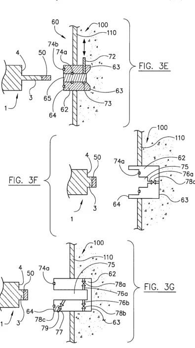
FIGS. 3A through 3G are schematic representations of the general methods, systems and/or apparatus of the invention
40 illustrating interfacing across a barrier defining a portion of
the fluidic system. An apparatus of the invention can be useful in connection
with fluidic systems for monitoring a property of a fluid therein. Generally, the apparatus of the invention comprise a personally portable sensor such as a mechanical resonator sensor (e.g., flexural resonator sensor) or a personally por- 45
table subassembly thereof. In preferred embodiments, the sensor or sensor subassembly comprise one or more of the following, in any of the various permutations/combinations:
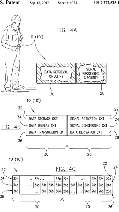
FIGS. 4A through 4C are schematic representations of a ported sensor subassembly comprising signal processing circuitry and/or data retrieval circuitry.
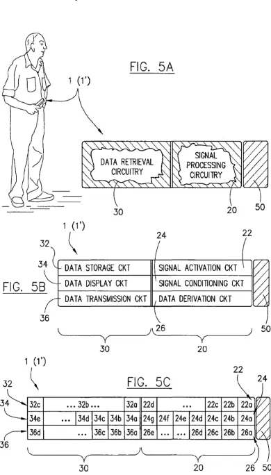
FIG. SA through SC are schematic representations of a ported sensor comprising signal processing circuitry and/or data retrieval circuitry.
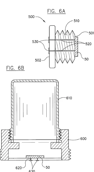
FIGS. 6A and 6B are section views of some preferred apparatus of the invention.
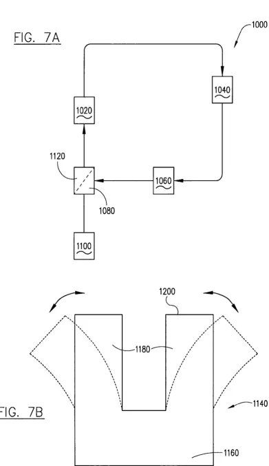
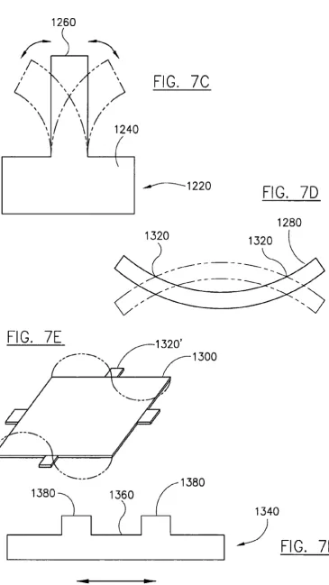
FIGS. 7A through 71 are schematic representations of a fluidic system (FIG. 7A) and of several configurations for flexural resonator sensing elements (FIG. 7B through 71). a sensing element (e.g, flexural resonator sensing element)
having a sensing surface for contacting a fluid; signal 50
processing circuitry adapted for or configured for processing raw data or previously-processed data or retrieved data (e.g., previously stored or transmitted data); and/or data retrieval circuitry for retrieving data (e.g., data storage circuitry, data display circuitry and/or data transmittal circuitry). In pre-ferred embodiments, the signal processing circuit is in or is adapted for or configured for receiving an signal (directly or indirectly) from a flexural resonator sensing element during
FIGS. 8A through 8C are a schematic representation of an equivalent circuit for a sensor comprising a flexural
reso-55 nator sensing element (FIG. 8A) and of equations relating
thereto (FIG. 8B and FIG. 8C).
a sensing period and processing that received signal. The processing of the received signal preferably effects a data output, for example, via the data retrieval circuitry, that can be useful for cOllll11lmicating a status or condition of the fluid to a person upon operation of the sensor in cOlmection with the fluidic system.
The present invention offers significant advantages over previously-known approaches for monitoring a fluid in a fluidic system. In particular, the invention offers substantial
FIGS. 9A through 9E are schematic representations of one preferred approach for circuitry that can be used in connec-tion with embodiments of the invenconnec-tion, at least a porconnec-tion of
60 the circuitry being realized in an application specific
inte-grated circuit (ASIC).
FIGS. lOA through lOD are schematic representations of alternative approaches for realizing circuitry in an ASIC.
FIGS. lIA through lID are schematic representations of
US 7,272,525 B2
7
of fluidic systems, and for warehousing such generated data (or a selected subset thereof) in one or more common database (e.g., as a remote data repository).
FIGS. 12 A through 12C are tables listing preferred application areas (fields of use), fluidic systems and fluids for which the methods, systems and apparatus of the inven-tions can be employed.
The invention is described in further detail below with reference to the figures, in which like items are numbered the same in the several figures.
DETAILED DESCRIPTION OF THE INVENTION
8
form-specifically by interfacing a (first) portable and ported subassembly 10 (shown as 10' in its disinterfaced position) and a (second) installed sensor/sensor subassem-bly, typically comprising a sensing element 50. The second sensor/subassembly (e.g., comprising sensing element 50) can be preinstalled within the fluidic system 100, relative to the time at which the first subassembly 10 is ported to the fluidic system. Significantly, the segmentation of the inter-faced sensor device 80 provides a technical basis which
10 allows for efficient and economically attractive approach for monitoring fluids within a fluidic system 100 (e.g., for process control, quality control and/or servicing needs), because the first ported subassembly 10 (10') can be inter-The following paragraphs describe certain features and 15
combinations ofteatures that can be used in connection with
mittently interfaced with installed sensors/sensor subassem-blies at numerous locations on the same fluidic system or on numerous different fluidic systems and in either case, at each of the methods, systems and apparatus of the invention,
as generally described above. Also, particular features described hereinafter can be used in combination with other described features in each of the various possible combina- 20
tions and permutations. As such, the invention is not limited
numerous various times. Segmentation of the interfaced sensor 80 into an discretely packaged functional units, at least one of which is portable/ported, provides an economic and operational flexibility benefit over componently-fixed (e.g., "hard-wired/hard-plumbed") installed solutions for monitoring of numerous fluidic systems. In some cases, it provides a unique solution for fluidic systems that could not otherwise be multiplexed using componently-fixed (e.g., to the specifically described embodiments.
Preferred General Methods
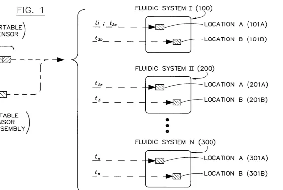
A preferred general method of the invention can be described, for example, with reference to FIG. 1, in which a ported sensor 1 or ported sensor subassembly 10 is inter-faced with the (first) fluidic system 100 (indicated as "Flu-idic System I") at a (first) location lOlA (indicated as "Location A"). Using the interfaced sensor, the fluid is sensed during a first sensing period (indicated as "tl ") to generate data, which is then stored, displayed or transmitted using the data retrieval circuit of the interfaced sensor. After the first sensing period, the portable sensor 1 or sensor subassembly 10 is disinterfaced from the (first) location lOlA of the (first) fluidic system 100, and ported away therefrom. Thereafter, the sensor 1 or sensor subassembly 10 can be (re)ported back to the same first fluidic system 100 at the same location lOlA for sensing the fluid again during a later in time second sensing period (indicated as "t2,,"). Additionally or alternatively, thereafter the sensor 1 or sensor subassembly 10 can be (re)ported back to the same first fluidic system 100, but at a different (second) location 10m (indicated as "Location B") for sensing during a later in time second sensing period (indicated as "t2b"). In addi-tion or in the alternative to the aforemenaddi-tioned, thereafter the sensor 1 or sensor subassembly 10 can be ported to a second fluidic system 200 (indicated as "Fluidic System II") that is separate and discrete from the first fludic system 100, and having a first location 201A (indicated as "Location A") and optionally having a separate and distinct second location 20m (indicated as "Location B"). The sensing can be effected at the first location 201A of the second fluidic system 200 during a second sensing period (indicated as
"t2c"). Further sensing can thereafter be effected at other
locations during other sensing periods. For example, there-after, the sensing can be effected at the second location 20m of the second fluidic system 200 during a third sensing period (indicated as "t3 "). In like generalized manner, the
sensing can thereafter be effected at one or more locations 301A, 30m of additional fluidic systems 300 (indicated as "Fluidic System N") during an nth sensing period (indicated
as "tn").
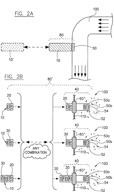
In a further generally preferred approach of the general method, with reference to FIGS. 2A and 4A, an interfaced sensor 80 is formed by interfacing at least one ported subassembly to forn1 the interfaced sensor 80 in segmented
25 hard-wired) monitoring systems, including for example a fluidic system on a fleet of aircraft or a fleet of trucks or a fleet of cars). The particular segu1entation approach is not narrowly critical to the invention. Generally, the installed sensor/sensor subassembly (typically already residing in
30 physical local association with the fluidic system) comprises
a sensing element 50 (e.g., mechanical resonator such as a flexural mechanical resonator) having a sensing surface positioned (meaning already positioned or adapted to be positionable) for contacting the fluid. The installed sensor/
35 sensor subassembly may, optionally, also include one or more additional sensing elements (of the same type--e.g. an additional flexural resonator, or of a different type-e.g., a temperature sensing element or pressure sensing element) and/or one more signal processing circuits (e.g., a signal
40 conditioning circuit such as an amplifier circuit, and/or e.g., a data derivation circuit such as a signal detection circuit) and/or one or more data retrieval circuits (e.g., a data storage circuit, a data display circuit, a data transmission circuit) for storing, displaying or transmitting data originating from the
45 sensing element, before or after signal processing in a signal processing circuit. Generally, the ported sensor subassembly 10 (10') comprises one or more data retrieval circuits 30 in electrical communication with the sensing element 50 (e.g., flexural resonator)--either directly or indirectly (e.g., via a
50 signal processing circuit 20). The data retrieval circuit
comprises circuitry adapted for storing, displaying or trans-mitting data. The ported subassembly 10 may, additionally or alternatively, also include one or more signal processing circuits 20 (e.g .. an amplifier circuit) for processing (e.g.,
55 amplifying) the (previously processed and/or raw) data
sensed by the sensing element and/or for processing a data stream from a data retrieval circuit (e.g., a data stream from a stored memory circuit). Further details and particularly preferred embodiments of forming the interfaced sensor
60 from the segmented subassemblies-specifically from the
ported subassembly and the installed subassembly, including specific apparatus adapted therefore, are described below, and each of the below-described details are specifically considered in various combination with this and other
gen-65 erally preferred approaches described herein.
US 7,272,525 B2
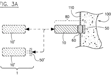
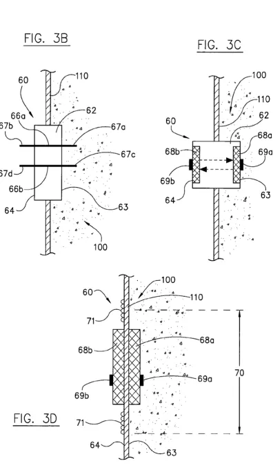
9
subassembly 10, or altematively the ported sensor 1 in its entirety, is interfaced with the (first or second) fluidic system 100 across a physical barrier 110 defining a portion of the fluidic system 100. The physical barrier 110 can include any portion of the physical structure which contains the fluid within the fluidic system. Hence, the barrier 110 can be, for example, the surface (e.g., wall, bottom) of a container, or the surface (e.g., peripheral wall) of a conduit. Preferably, the ported sensor 1 or ported sensor subassembly. 10 is interfaced across the barrier 110 without compromising the 10
integrity of the fluidic system 100. The integrity of the fluidic system is not compromised if the fluidic system remains substantially intact-without substantial loss of fluid material and/or without substantial reduction of fluid pressure during the interfacing step. The amount of lost material or reduced pressure that would be substantial depends generally on the system and operational consider-ations, but is generally not more than about 10%, preferably not more than about 5%, more preferably not more than about 2% and most preferably not more than about 1 %, based on total amount or total absolute pressure, respec-tively. Further details of interfacing the ported sensor or ported sensor subassembly across the barrier, including specific apparatus adapted for such interfacing, are described below, and each of the below-described details are 25
specifically considered in various combination with this and other generally preferred approaches described herein.
15
20
10
fluidic system at various times as necessary or desired, and in each case, interfaced and used for sensing the fluid, for example as described in any of the aforementioned general methods. Hand-portable sensors or sensor subassemblies provide substantial advantages, including especially for remote field operations and/or for centralized service appli-cations on mobile fluidic systems and/or for monitoring or servicing of complex fluidic systems (having multiple inde-pendent fluidic systems) or geometry-constrained (e.g., densely packed) fluidic systems. In these and other appli-cations, hard-configured multiplexing systems may be inef-ficient and/or cost-prohibitive. In contradistinction, hand-held systems provide the benefits of multiplexing without creating umlecessary and largely unused or underutilized redundancies in sensing systems or components thereof. Further details of using hand-held sensors and hand-held sensor subassemblies in the methods of the present inven-tion, including specific apparatus adapted therefor, are described below, and each of the below-described details are specifically considered in various combination with this and other generally preferred approaches described herein.
Each of the aforementioned generally preferred approaches can be applied independently or in combination with each other, in each of the possible various permuta-tions. Also, each of the aforementioned generally preferred approaches can be applied in further combination with more particular aspects, including particular protocols and/or par-ticular apparatus features, as described below.
30 Preferred General Systems and Apparatus In another generally preferred approach of the general
method, with reference to FIG. 3A the ported sensor 1 or ported sensor subassembly 10 is ported and interfaced, for example as described in any of the aforementioned general methods. The fluid is sensed using the interfaced sensor 80 and the data generated in the sensing step (i.e., whether processed data or raw data) is stored, displayed or transmit-ted using the data retrieval circuit. One or more of the storing 35
step, the displaying step or the transmitting step comprises communicating with the data retrieval circuit of the ported sensor 1 or ported sensor subassembly lOusing a wireless c0l11l11lmication protocol. As used herein, a wireless com-munication protocol includes at least one transfer of data 40
using electromagnetic radiation. The wireless conmmnica-tion can generally be between the data retrieval circuit of the ported sensor or ported subassembly and an installed sensor/ sensor subassembly comprising a sensing element (e.g., a mechanical resonator such as a flexural resonator), and 45
optionally, an installed signal processing circuit (e.g., ampli-fying circuit) and optionally, an installed (second) data retrieval circuit. Additionally or altematively, the wireless communication can generally be between the data retrieval circuit of the ported sensor or ported subassembly and a 50
wireless C0l11l111mication receiving circuit at a remote loca-tion (e.g., installed in a service truck parked relatively nearby the fluid-sensing location). Further details of wireless communication protocols involving the data retrieval circuit of the ported sensor or ported sensor subassembly, including 55
specific apparatus adapted for such communication, are described below, and each of the below-described details are specifically considered in various combination with this and other generally preferred approaches described herein.
In yet a further generally preferred approach of the 60
general method, with reference to FIGS. 4A and 5A, the ported sensor 1 (1') or ported sensor subassembly 10 (10') is a hand-held (i.e., personally portable) device. The hand-held device can comprise a hand-held sensor (in its entirety) or a hand-held sensor subassembly (e.g., as described above and 65
below in cOlmection with segmented assemblies) and in either case, can be ported by a person to the (first or second)
The present invention also include devices effective for monitoring fluids in fluidic systems according to the afore-mentioned methods. In general, such devices are systems or apparatus that comprise one or more sensors, and/or that comprise one or more sensor subassemblies adapted for or configured for interfacing with one or more other sensors/ sensor subassemblies to form an interfaced sensor that is operational or that has enhanced operational functionality.
A preferred general system of the invention can comprise an interfaced sensor in a fluidic system, where the interfaced sensor comprises a sensing element, and at least one or both of a data retrieval circuit or a signal processing circuit.