ISSN Online: 2329-8413 ISSN Print: 2329-8421
A Very Compact Circular Adaptive Array for
New Generation Mobile Commercial Receivers
Antonis A. Constantinides
Institute of Work Based Learning Middlesex University, London, UK
Abstract
The antenna is a receiver’s component that collects electromagnetic waves from various directions. The rationale behind focusing on the circular array is that its tuning ensures that the receiver processes the desired signal only, while rejecting the unwanted interference. This can only be achieved by a di-rectional external antenna that is large in size and must be steered mechani-cally in the desired direction. As this arrangement is not practical, smart an-tennae have been proposed as an alternative. A circular phased array can produce a predicted radiation pattern, whereby it receives maximum energy from the desired direction without the need for mechanical control. Owing to these characteristics, phased arrays exhibit high gain as well as immunity to interference, making them ideal for use in high interference environments. This combination would ensure that it could be incorporated into a commer-cial deck receiver or installed on vehicles.
Keywords
Normal Mode Helical Antenna, Radio Services, Impedance, Bandwidth, Gain
1. Introduction
Today, the commercial car’s receivers employ vertically polarized antennae, which receive signals from all directions with equal density. As a result, a tradi-tional vertically polarized antenna cannot distinguish the desired signal from the interference, as both penetrate into the receiver, despite arriving from different directions. Based on this concept, a phased array utilized for reception purposed in mobile communications can minimize the level of interference very efficiently as its main beam steers in the desired direction in order to disable penetration of all other incoming (undesired) signals transmitted from the side and back posi-tions. The main beam’s tilt direction of a phased array depends on the phase How to cite this paper: Constantinides,
A.A. (2017) A Very Compact Circular Ada- ptive Array for New Generation Mobile Commercial Receivers. Open Journal of Antennas and Propagation, 5, 1-6.
https://doi.org/10.4236/ojapr.2017.51001
Received: December 1, 2016 Accepted: January 20, 2017 Published: January 23, 2017
Copyright © 2017 by author and Scientific Research Publishing Inc. This work is licensed under the Creative Commons Attribution International License (CC BY 4.0).
shift as well as the amplitude difference among the single elements that consti-tute the system [1]. As a result, the greatest advantage of this approach stems from dispensing with the need for mechanical movement, as the main beam of a phased array steers toward the desired direction [2]. For instance, Howard and Fung [3] conducted their study, focusing on an antenna, which they labelled “Clever Dumb Antenna” in reference to its ability to derive the great benefits of the multi-beam antennas interfaced by a beamformer. According to the authors, “the great benefit of such antennas enables dividing up to 360 degree cell site in-to several high gain secin-tors”. It is important in-to note that a beamformer the au-thors refer to is a signal processing technique based on a network comprised by phase shifters that enable programming of the adequate phase shift of the radia-tors in order to produce an optimum radiation pattern as well as beam tilt. In a different study, Panduro [4] presented a non-uniform circular phased array, ferring to it as a smart antenna, due to its ability to provide a low side lobe re-sponse for scanning purposes. As the side lobes are minor beams, scanning an-tennas enable reception from different angles of the main beam. Owing to these properties, low side-lobe response arrays are primarily aimed for use in a high interference environment. Furthermore, Winters and Gil [5] extended the afore- mentioned research by examining the parameters of the two major categories of smart antennas, namely the phased and adaptive arrays. The adaptive arrays’ radiation pattern, as the authors’ state, “It is auto adjusted according to the move of interference, the phased arrays” radiation pattern are not. They further ex-plained that “it is steered or different beams are selected as the desired user moves”. According to this view, the smart antennas are highly recommended for new generation wireless communications. Presently, they are being applied ex-perimentally in 4G/5G wireless radio communication systems and it is likely that their range of applications will expand in the future, given that this promising area of research will be explored for many years to come.
2. The Adaptive Array Topology
Circular arrays are one-dimensional linear arrays in a circular form. The major advantage of circular arrays relative to linear arrays stems from their ability to scan horizontally across the entire 360˚ without distortion near the end-fire
di-rection [6]. Therefore, circular arrays present the ideal topology for this applica-tion and will be investigated in detail in this secapplica-tion. Another great advantage of circular arrays is that the mutual coupling affects all individual elements of the array with equal density. Therefore, eliminating it is easier than in any other to-pology [7]. The array factor of circular arrays is the sum of the far-field intensity of every individual element of the array and is given by Equation (1):
[ sin cos( - ) ]
1 j n n
N e
n βα θ Φ Φ + ∆
∑ = (1)
where ∆n is the excitation phase of every individual element (in this applica-tion, the normal mode helix antenna). The maximum radiation angle (Θmax,
(
)
(
)
1 2sin max cos max 2
a B q
N
π
β Θ Φ − + =−+ π (2)
(
)
(
)
24
sin max cos max 2
a B q
N
π
β Θ Φ − + =−+ π (3)
(
) (
)
sin max cos max 2 N 2
a B q
β Θ Φ − π + =−+ π (4)
The maximum radiation direction in terms of the excitation phase is given by Equation (5) below:
(
)
(
2)
2 sin max cos max
N
n
B q a
N
π π β
= + − Θ Φ − (5)
N = 1, 2, 3.
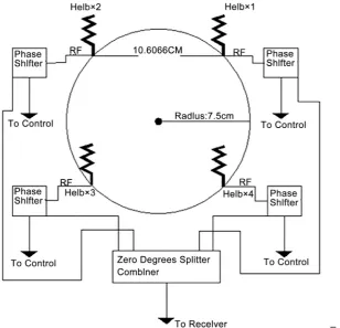
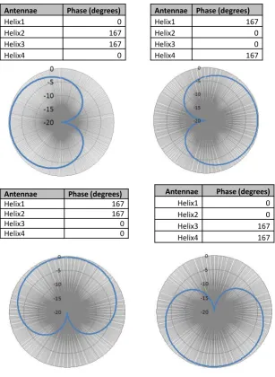
[image:3.595.222.531.417.714.2]Based on the preceding discussions, the performance of a four-element circu-lar array, illustrated in Figure 1, is analyzed to ensure that it operates effectively in the 87.5 - 108 MHz range. The circular array shown above comprises of four modified normal mode helical antennae. The antennae are mounted at a 900 distance. The phase of every individual helical antenna is controlled by an elec-tronic phase shifter (Mini-Circuits JSPHS-150+) in order to create the desired radiation pattern in a given direction. The radius of the circle is 7.5 cm, which corresponds to 0.025λ. In this respect, the radiation pattern of the four-element circular array in the end-fire direction will be analyzed below, according to the phase shift of every individual element. The weights and radiation patters are presented in Figure 2.
Figure 2. The smart Antenna phase shifts simulation and radiation patterns.
3. Test and Results
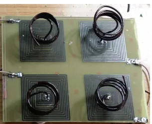
The array consists of four NMHA, constructed on an FR-4 PCB, while the array is shown in Figure 3. In order to evaluate the array performance, the Voltage Standing Wave Ratio VSWR (caused by the mutual coupling between the ele-ments and compensated for by rotating the helix) was first minimized for every individual helix. The gain of the four-element circular array relative to the per-formance of the whip telescopic antenna was evaluated by primarily steering electronically the array towards the direction of the maximum radiation of the incident waves monitored via the spectrum analyzer shown in Figure 4. The monitored radio services are three local channels utilizing 91.6 MHz, 93.3 MHz and 93.7 MHz frequencies. All monitored radio services are broadcasting from the same direction. The spectrum analyzer readings were obtained by utilizing the spectrum analyzer ROVER-DL1. The maximum radiation is illustrated in Figure 4, which reveals the field strength of 93.3 MHz is 33.7 dBuV versus 33.5
Antennae Phase (degrees)
Helix1 0
Helix2 167
Helix3 167
Helix4 0
Antennae Phase (degrees)
Helix1 167
Helix2 0
Helix3 0
Helix4 167
Antennae Phase (degrees)
Helix1 167
Helix2 167
Helix3 0
Helix4 0
Antennae Phase (degrees)
Helix1 0
Helix2 0
Helix3 167
Figure 3. The four-element circular array.
Figure 4. Real conditions spectrum analyzer readings of the circular array.
[image:5.595.223.528.548.717.2]dBuV obtained for the traditional whip telescopic antenna has been tested pre-viously. As a result, the gain of the four-element array in Band II is very satis-factory. The next highly important test performed as a part of this work aimed to determine the null, created by the arranged phase shift by electronically rotating the array by 180˚ in the opposite direction of the transmitting point. As a result
of this adjustment, the field strength of the strongest radio service (which is 33.7 dBuV) declined to 9.9 dBuV, as illustrated in Figure 5. It is important to note that the field strength of the other two adjacent channels (91.6 MHz and 93.7 MHz, illustrated in the spectrum analyzer in Figure 5), broadcasting from the same transmitting point, was also reduced significantly.
As a result, it can be asserted that the four-element circular array has enabled a reduction in gain of around 24 dB in the opposite direction of the transmitting point, which complies with the radiation patterns simulated in the previous sec-tion.
4. Conclusion
Applying the circular array as it has been implemented in this study in Band III (174 to 240 MHz) for Digital Audio Broadcasting (DAB+) will enhance the SNR of digital receivers during motion. Circular array can also be a very important technology for the future mobile digital video broadcasting terrestrial (DVB-T) service that broadcasts television in UHF Band between the channels 21 and 69 (i.e. in the 512 - 800 MHz frequency range).
References
[1] Rabinovich, V. (2011) Direction Finding System for Automotive Applications Using Small Phased Antenna Array. Microwave and Optical Technology Letters, 53, 2441- 2446. https://doi.org/10.1002/mop.26275
[2] Lee, M. and Kim, Y. (2009) Development of a K-Band FMCW Phased Array Radar Sensor with Low Complexity Receiver Based on Antenna Switching. Microwave and Optical Technology Letters, 51, 2848-2850. https://doi.org/10.1002/mop.24785
[3] Howard, J. and Fung, C. Clever Dumb Antenna: Passive Multibeam Antenna for Broadband Wireless Communication.
[4] Vedula, V., Paladuga, S. and Prithvi, M. (2015) Synthesis of Circular Array Antenna for Sidelobe Level and Aperture Size Control Using Flower Pollination Algorithm.
International Journal of Antennas and Propagation, 2015, 1-9.
https://doi.org/10.1155/2015/819712
[5] Winters, J. (1998) Smart Antennas for Wireless Systems. IEEE Personal Communi-cations, 5, 23-27. https://doi.org/10.1109/98.656155
[6] Davies, D. and Rizk, M. (1977) Electronic Steering of Multiple Nulls for Circular Arrays. Electronics Letters, 13, 669. https://doi.org/10.1049/el:19770475
[7] Hui, H.T. (2007) Decoupling Methods for the Mutual Coupling Effect in Antenna Arrays: A Review. Recent Patents on Engineering, 1, 187-193.
Submit or recommend next manuscript to SCIRP and we will provide best service for you:
Accepting pre-submission inquiries through Email, Facebook, LinkedIn, Twitter, etc. A wide selection of journals (inclusive of 9 subjects, more than 200 journals)
Providing 24-hour high-quality service User-friendly online submission system Fair and swift peer-review system
Efficient typesetting and proofreading procedure
Display of the result of downloads and visits, as well as the number of cited articles Maximum dissemination of your research work