Honeywell
Interoffice CorrespondenceDate:
To:
From:
Location:·
Subject:
761221 section:
14.5
doc'
0110A-OArchitecture File page
.
.
1Lou Krasny
'-I
K
LA DC
L66B Interrupt System
1.0 INTRODUCTION
The purpose cJ this document is to provide the CP-6 designer with an overview of the L66B interrupt system architecture. The L66B system is made up of a Level 66 CPU with the Virtual Memory and Security Option, the 4 h\egaword System Con-troller, and the 6oo0B 10M with the IOM-B Paging Mechanism. In this document I have attempted to present the information in an orderly manner starting with a description of the individual flip-flops and storage registers involved in the interrupt system and then proceeding to a chronological description of the. events that take place in the various system components. I have described the interrupt system as it will exist on the hardware that we expect to use for CP-6; the operation of earlier systems deviates sign ificantly from that described here.
The information in this document has been obtained from the following HIS docu-ments:
EPS-1 6000 Processor, 43A21960 1 EPS-1 6000 EIS Processor, 43A232719
EPS-2 6000 EIS Central Processor, 43A240154 EPS-1 4 Megaword System Controller, 58001190 EPS-2 6000B System Controller, 43A 177770 EPS-1 60008 10M Central, 43A239854 EPS-2 IOM-B, 43A 177745
EPS-1 10M Peripheral Subsystem Interface Adapter, 43A 177880 EPS-1 Direct Channel, 43A239853
Series 60 (~y~1 66)/6000 Macro Assembler Program (GMAP), 0008
3.0 DEFINITIONS
CPU - Central Processing Unit - the hardware module that fetches, interprets, and executes the instruction set of the l66B computer system.
-SC - System Controller - the hardware module that provides intra-system communi-cations between storage modules (main memory) and active modules {processors and input/output modules}.
10M - Input/Output Multiplexer - the hardware module that is the physical interface between the system and its peripheral devices. This hardware module contains the channe Is to which the periphera Is connect and the channe Is used to transfer data directly associated with the operation of the system. The 10M is connec-ted to a port on the system controller.
4.0 INTERRUPT CELLS
Each SC has 32 interrupt levels which are called interupt cells in the SC documenta-tion. A ce II is not a memory location; it is a flip-flop within the SC. For CP-6 we will be concerned only with the interrupt cells in the first SC even if there is more than one SC configured on a particular system. In the following discussion, all expli-cit and impliexpli-cit references to the SC will be to the first SC.
In Sigma terminology, each individual interrupt ce II is either in the armed state or the waiting state. An interrupt cell which is set to a tlO" is in the armed state which means that it can accept and remember an interrupt request. An interrupt cell which is set to a "1 II indicates that that interrupt level has been triggered and is in the
waiting state. Interrupt cells in either the armed or waiting state can be individu-ally enabled or disabled depending on the contents of an Interrupt Mask Register to be described later.
Under program control, a CPU operating in privileged master mode can read the state of all 32 interrupt cells by executing a specific variation of the Read System Controller Register (RSCR) instruction.
A CPU operating in privileged master mode can change the state of any of the 32 intemJpt cells as follows:
1. By executing a specific variation of the Set System Controller Register (SSCR) instruction. This instruction unconditionally sets or resets all 32 interrupt ce lis according to the contents of the CPU Accumulator Quotient (AQ) register.
2. By executing a Set Memory Controller Interrupt Cells (SMIC) instruction. This instruction can set selected interrupt cells as specified by the contents of the CPU Accumulator (A) register. Interrupt cells cannot
be
reset bysection: doc' date . page
14.5
0110A-O 7612213
An 10M connected to a port on the SC can set 8 of the 32 interrupt ce lis. Each 10M connected to the SC is assigned a different group of 8 interrupt cells.
Table 4.1
shows
the 10M related assignment of all 32 interrupt cells for indirect channels. Notice that the first four interrupt cells are not usedby
10M indirect channels.Table 4.1
ASSIGNMENT OF INTERRUPT CELLS FOR 10M INDIRECT CHANNELS
INTERRUPT CELL NO.
o
1 2 34
5
6 7 8 9 10 11 12 13 14 15 16 17 18 19 20 2122
23 2425
26 27 28 29 30 3110M NO.
o
1 2 3o
1 23
o
1 2 3o
1 2 3o
12
3o
1 23
o
1 2 3o
1 23
ASSIGNMENT Not Used Not Used Not Used Not UsedOverhead Channel Interrupts Overhead C hanne I Interrupts Overhead Channe I Interrupts Overhead Channel Interrupts
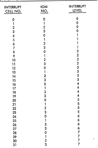
An interrupt service request on a direct channel interface allows the external system to specify a 3-bit interrupt level number. The 10M in response to this direct
channel interrupt service request sets the interrupt cell as indicated in Table
4.2.
Table
4.2
ASSIGNMENT OF INTERRUPT CELLS FOR 10M DIRECT CHANNELS
INTERRUPT CELL NO.
[image:4.612.150.488.205.714.2]5.0 INTERRUPT MASK REGISTERS
section:
doc'
date page
14.5 0110A-O 761221 5
Each SC contains four 32-bit Interrupt Mask Registers. Each individual bit of an Interrupt Mask Register is associated with one of the 32 interrupt cells. These mask registers perform the function of enabling and disabling individual interrupt cells within the SC. A specific bit of an Interrupt Mask Register set to a 110 11 indi-cates that the corresponding interrupt cell is in the disabled state. A specific bit of an Interrupt Mask Register set to a 11111 indicates that the corresponding interrupt ce II is in the enab led state.
Under control of switches on the SC configuration panel, each of the four Interrupt Mask Registers can be marked as unassigned or can be assigned to one of the eight ports wh ich connect the SC to CPU's and IOM's. An Interrupt Mask Reg ister is never assigned to a port connected to an 10M.
An
Interrupt Mask Register must be assigned to each port connected to a CPU that is to respond to interrupts. AnInterrupt Mask Register cannot be assigned to more than one port at any time and more than one Interrupt Mask Register should not be assigned to the same port.
When one of the Interrupt Mask Reg isters is assigned to aport, each bit of that 32-bit Interrupt Mask Register acts as an enable control for the corresponding inter-rupt cell in determining whether an interinter-rupt signal will be transmitted to the CPU connected to that port. When a bit in the Interrupt Mask Register is a "1" and the corresponding interrupt cell is set to a til tI, an interrupt signal is sent to the CPU.
When a bit in the Interrupt Mask Register is a
"0",
the corresponding interrupt cell can be set to a til II; however, no interrupt signal will be sent to the CPU at that time as a result of that interrupt level. If at a later time the Interrupt Mask Register bit is set to a"111
and the corresponding interrupt ce II is still set to"1",
the interrupt signal will be sent to the CPU.
A CPU operating in privileged master mode can determine which port each of the four Interrupt Mask Registers is assigned to by executing a specific variation of the Read System Controller Register (RSCR) instruction.
A CPU operating in privileged master mode can read the Interrupt Mask Register assigned to it by executing a Read Memory Controller Mask Register (RMCM) instruc-tion. A CPU operating in privileged master mode can set or reset all 32 bits of the Interrupt Mask Register assigled to it by executing a Set Memory Controller Mask Register (SMCM) instruction.
privileged master mode can set or reset all 32 bits of the Interrupt Mask Register assigned to any port by executing a specific variation of the Set System Controller Register (SSCR) instruction.
Both
of the instructions wh ich a How a CPU to modify the contents of one of the Interrupt Mask Registers cause all 32 bits of that Interrupt Mask Register to be set or reset at the same time. There is no single instruction that allows a CPU to modify some of the bits of an Interrupt Mask Register while leaving the other bits unmodified.6.0 INTERRUPT MULTIPLEX WORDS
The Interrupt Multiplex Words are a set of 32 contiguous words located in main memory that are used to communicate the channel number of an interrupting channel from the 10M hardware to the CPU software. The contents of an Interrupt Multi-plex Word are modified by the 10M hardware prior to setting an interrupt ce II.
Interrupt Multiplex Words have no effect on the hardware portion of an interrupt operation in either the SC or the CPU. In response to an interrupt, CPU software can interrogate the contents of one or more Interrupt Multiplex Words.
Interrupt Multiplex Words are located in the lower 256K of real memory on a 32 word boundary as specified by 13 switches on the SC configuration panel. The Interrupt Multiplex Word address is always interpreted as a real address. There is a one to one correspondence between each Interrupt Mu Itiplex Word and each interrupt ce II; e.g., the 12th Interrupt Multiplex Word is associated with interrupt cell number 12.
Each of the first 32 bits of each Interrupt Multiplex Word is associated with a speci-fic channel within the 10M. The bit number within an Interrupt Multiplex Word _ that is assoc iated with a channe I is determ ined by the low order 5 bits of the channe I number.
7.0 10M INTERRUPT SERVICE
The following are the steps executed by the 10M hardware in performing an interrupt service:
1. Using a read and clear operation, the 10M accesses the Interrupt Multiplex Word associated with the interrupt cell that the 10M wishes to set. The read and c lear operation is executed by the memory system as a sing Ie oper-ation, thereby providing a reliable IImultiprocessor gatingll
function.
section:
doc'
date page
14.5
0110A-o
761221
7
3. The 10M stores the modified Interrupt Multiplex Word back into memory.
4. The 10M requests that the SC set the appropriate interrupt ce II to a 11)11.
8.0 INTERRUPT SIGNAL TO CPU
There is an interrupt signal line on each port of the SC. This interrupt signal will always be in the false state for every port which has no Interrupt Mask Register assigned to it. For a port which has an Interrupt Mask Register assigned to it, the
interrupt signa I will be in the true state whenever there is at least one interrupt level for which a bit in the Interrupt Mask Register assigned to that port and the cor-responding interrupt ce II are both set to the 11111 state.
9.0 CPU RESPONSE TO INTERRUPT SIGNAL
When an interrupt signal is received by the CPU, the CPU will carry out the interrupt procedure as soon as an instruction from an odd memory location has been executed that:
1. Did not have its interrupt inhibit (bit 28) set to a 1.
2. Did not cause an actual transfer of control. (A transfer of control is effec-ted if the instruction is an unconditional transfer, a conditional transfer with the condition satisfied, or an instruction generated fau It.
3. Was not an Execute or Execute Double (XEC or XED) instruction. (An XEC or XED instruction and the one or two instructions carried out under instruc-tion control are regarded as a single instrucinstruc-tion execuinstruc-tion.)
4. Was not accessed while in the repeat mode or was not the instruction follow-ing the termination of the repeat mode.
5. Was not a CLIMB instruction.
10.0 CPU INTERRUPT PROCEDURE
When the above conditions are satisfied, the CPU executes the following interrupt procedure:
1 • The CPU enters the master mode. (The master mode indicator ts not affected.)
3. In response to the Read Program Interrupt Cells command, the SC returns to the CPU a 5-bit code containing the cell number of the lowest num-bered interrupt cell that is currently set and whose corresponding bit in the
Interrupt Mask Register is a Iso currently set. The SC then resets the inter-rupt ce II whose number was returned to the CPU.
4. The CPU executes a "wired in II CLIMB instruction which obtains an Entry
Descriptor from rea I memory locations 30 and 31 (octa I) • The hardware makes the following assumptions concerning the second word of this
"wired in" CLIMB:
Bit 0 = 0
- NC?
pclrcmeters are passed.Bit 18 = 0 - Do not change XO.
Bit 19 is ignored and the Master Mode bit of the Indicator Register is set to a "111.
Bits 22-23=00 - CALL type of CLIMB: context is saved in Safe Store Stack.
Bits 24-35 are ignored and an Entry Descriptor is obtained from real me":,ory locations 30 and 31 (octa I) •
The ~_-bJt interrupt cell number is saved in bits 13-17 of word 5 of the safe store frame and bit 12 of the same word is set to a "111. The CLIMB instruc-tion is not interruptable.
There is an alternate action for step 3 which can occur in a multi-CPU case or in the single CPU case where the CPU resets its Interrupt Mask Register after the inter-rupt signal is received by the CPU but before the CPU has initiated the interinter-rupt procedure. If in responding to the Read Program Interrupt Ce lis command from a port, the SC finds no enabled waiting interrupts for that port, a unique response is returned which causes the.CPU to return to the interrupted program without executing a CLIMB instruction and without involving the software in any way.
It should be noted that this is not a true priority interrupt system since the hardware retains no record of the interrupt level currently being processed by the software.
section:
doc'
elate page
14.5
0110A-O
761221
9In processing an interrupt from an 10M, the following steps may be executed by the system software to determine which channel caused the interrupt:
1. The Interrupt Multiplex Word associated with the interrupt level received can
be
accessed by the CPU using either a Load A and Clear (LDAC) instruc-tion or a load 0 and Clear (LDOC) instrucinstruc-tion. These are the only two CPU instructions that perform a single read and clear operation at memory.2. If the Interrupt Multiplex Word is non-zero, each one bit identifies a chan-nel on the 10M that requested an interrupt service.
3. If the Interrupt Multiplex Word is zero, one of three possible conditions has occurred: 1) The 10M is in the middle of setting another bit in the same Interrupt Mu Itiplex Word; 2) In responding to an earl ier interrupt, the CPU read the Interrupt Multiplex Word after the 10M completed the write back to memory but before the CPU was interrupted for the second interrupt; 3) In a multi-CPU environment where more than one CPU can receive interrupts, if more than one channel associated with the same