SUBJECT:
SPECIAL
INSTRUCTIONS:
DATE: October 1, 1968
OS02 SM 7.S969
Printed in U. S. A.
S
ERIE
S
200
PROGRAMMERS'
REFERENCE MANUAL
MODELS
200/1200
1250/2200
/
4200
The Central Processor Hardware of Series 200 Models 200, 1200, 12S0, 2200, and 4200; The
.Easycoder Assembly Language; Summary Infor
-mation concerning Programming Series 200 Peripheral Devices and the Scientific Unit. This edition completely supersedes revision of the Series 200 Programmers I Reference Manual (Models 200/1200/2200/4200), Order No. 139, dated November 10, 1966, and incorporates the information published in Addenda #1 and #2 to that manual. The portions of this publication containing new and changed information are indicated on page iii.
This volume and the manuals and bulletins per
-taining to the peripheral components of an in
-stalled Series 200 system together constitute a programmers I handbook for that system.
*
FILE NO. : 113. OOOS. 0000. 2-139PREFACE
This manual constitutes for the programmer a reference source of detailed information
concerning the central processor hardware of Series 200 Models 200, 1200, 1250, 2200, and
4200. The Easycoder Assembly Language, used with the Series 200/Basic Programming
Sys-tem and the Operating SysSys-tem - Mod 1, is also defined~ In addition, this volume contains sum-mary information concerning the programming of Series 200 peripheral devices and the scientific
unit. The hardware information presented herein is equally applicable for the programmer using
the Series 200/0perating System - Mod 2. However, for this usage it should be supplemented
by the information contained in Appendix C of the software manual Assembler J (Order No. 432).
Separate hardware manuals and bulletins contain detailed information about programming
and operating individual Series 200 peripheral devices. Specific peripheral device publications
are named in the tables of input/output control characters beginning on page 8-120 of this manual.
The only prerequisite for a thorough understanding of the information presented herein is
a familiarity with basic data processing terminology. No previous knowledge of the Series 200
is as sumed.
A programmers' handbook may be constructed by combining in a single binder this volume
and the manuals/bulletins pertaining to the peripheral components of the installed Series 200
system. This manual and the peripheral device manuals are all published in loose-leaf format
for ease of rapid updating by means of replacement-page addenda.
The equipment characteristics reported herein remain subject to change to allow the
intro-duction of design improvements.
Copyright 1968 Honeywell Inc.
Extensive functional descriptions and progranuning infornlation for the Model 1250 have
been added. New infornlation and new peripheral devices for all Series 200 processors have
been incorporated. Likewise, the infornlation carried over fronl revision 1 has been extensively
updated to correct technical error s and to enhance its clarity.
New infornlation and changes added to this publication since the last edition are indicated
below by page nUnlber and itenl.
Page Itenl( s) Page Itenl(s)
1-8 Tables 1-1 and 1-2 8-62 Note 4
Para. 3 8-63 Para. 3 and Table 8 -15
1-9 Table 1-3 and 8-64 Note 4
Para. 2 8-67 Note 2
1-11 Para. 2 and 3 8-82 Note 3
1-12 Table 1-7 8-85 Notes 6, 7, and 8
1-22 Note 5 8-86 All
1-23 Note 6 and Para. 4 8-87 All
1-24 All 8-88 All
2-4 All 8-8.9 All
2-5 All 8-90 All
2-6 Para. 1 8-92 Note 7
2-7 Table 2-2 8-94 All
2-10 Footnote 2 8-96 Note 3
2-17 Table 2-4 8-100 Note 4
5-19 Para. 5 8-111 Table 8-23
6-8 Para. 3 - Note 8-125 Note 1
8-15 Note 5 B-9 Table B-9
8-17 Note 5 C-9 Table C-2
8-21 Note 4 C-I0 Table C-2
8-23 Note 4 C-ll Table C-3
8-24 Note 7 F-4 Table F-l
8-26 Note 9 F-5 Table F-l
8-43 Note 3 F-6 Table F-l
8-55 Exanlple G-2 Para. 5
8-58 Table 8-12 G-3 Para. 3,4, and 5
8-60 Notes 4 and 5 Appendix H All
TABLE OF
CONTENTS
Section I
Section II
Series 200 COIl1.ponents 0 0 0 0 • 0 0 0 0 0 0 0 0 0 0 0 0 0 0 0 0 0 0 0 0 0 0 0 0 0 0 0 0 0 0
Central Processor 0 0 • • • 0 0 0 • 0 • • • • • • 0 0 0 0 0 0 • 0 • 0 0 0 0 0 0 0 0 0 0 0
Standard Processing Mode 0 0 0 0 0 • 0 0 • • 0 • 0 • 0 0 0 0 0 0 0 • 0 • 0 0 0
Interrupt Proces sing Mode 0 • • 0 0 0 0 • 0 0 0 0 0 0 0 0 0 0 • 0 • 0 • 0 • •
External Interr'upts . 0 • • 0 0 0 • 0 0 0 0 0 0 0 • 0 • 0 0 0 0 0 0 0 • • 0 0 0
Internal Interrupt ..• 0 0 0 • • 0 • 0 0 0 • 0 0 0 . 0 0 0 • 0 0 0 0 0 0 0 • 0 0
Addressing Modes 0 0 0 • • 0 • 0 0 0 • 0 0 0 0 0 0 0 • 0 .• 0 0 0 0 0 0 . 0 0 • • 0 •
IteIl1.-Mark Trapping Mode . . . 0 0 • 0 0 • 0 0 0 • 0 0 0 • 0 • 0 0 • • 0 0 0
Processing P'ower . 0 0 0 0 0 • 0 0 0 0 0 0 0 0 0 • 0 • 0 0 0 • 0 0 0 0 0 0 0 . 0 . 0
Peripheral EquipIl1.ent 0 0 0 0 0 0 • 0 • • • • 0 • 0 • 0 0 0 • • • • 0 • • • • 0 0 0
Peripheral Control o . 0 0 0 • 0 0 0 0 • 0 0 • 0 • 0 • 0 0 • 0 0 • • • 0 • 0 • 0 • 0
Punched Card EquipIl1.ent . 0 0 0 • • • • • • 0 0 • 0 • 0 0 • 0 • • 0 • 0 • 0 • 0
High Speed Printers .•• 0 0 0 • 0 • • 0 • • • 0 0 • 0 • 0 0 0 0 0 • 0 • 0 • 0 • 0
Print Buffer .. 0 • • • 0 0 0 • 0 • • 0 • 0 0 • 0 • 0 • 0 0 • • • 0 0 • 0 • 0 • 0 • 0
Magnetic Tape Units 0 0 0 0 • 0 0 0 • 0 • 0 0 0 0 0 • • • 0 • 0 0 0 • • 0 0 0 0 0 0 1200 BPI Recording Density ... 0 0 0 0 • 0 0 • • • • 0 • 0 0 . 0 0 • 0
Disk Pack Drives .. 0 0 • 0 • • 0 : 0 • 0 0 0 0 0 0 • • 0 • • 0 0 0 0 0 . 0 • • 0 • 0
Disk Files ... 0 0 • 0 • 0 0 0 • 0 0 • 0 0 • 0 • 0 0 • • 0 • 0 . . 0 0 0 • 0 • 0 • 0 0 0 0 0
RandoIl1. Acces s DruIl1.s 0 0 • 0 0 0 • • 0 • 0 • • 0 • • • 0 0 • 0 0 • 0 • 0 0 0 • 0
High -Speed Dr·uIl1.s . . . 0 0 0 • • 0 • • 0 • • • 0 • 0 • • • • • 0 0 0 • 0 • • 0 • • 0
Angular Position Indicator . . . . 0 0 0 • • • 0 0 0 • 0 0 • • 0 0 0 0 • • 0 • 0
Paper Tape EquipIl1.ent 0 0 • 0 • 0 • 0 0 0 0 0 • • • 0 0 • 0 • • 0 • 0 0 0 • 0 • •
Data COIl1.Il1.unication EquipIl1.ent 0 • • 0 • • • 0 • • • • • • • • • • • • • •
Cons ole EquipIl1.ent . . . 0 • 0 • 0 0 0 0 • 0 0 0 0 0 0 • 0 • 0 0 0 0 0 • • 0 • 0 0 • •
Visual InforIl1.ation Projection Devices . 0 0 0 0 0 0 0 0 0 0 0 0 0 • 0
Teller TerIl1.inal Equipment ... 0 • • 0 • 0 0 0 • 0 0 0 0 0 0 • 0 0 • • • • •
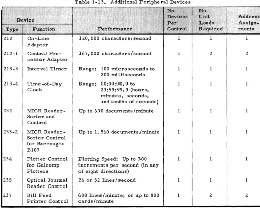
Additional Peripheral Devices . 0 0 • 0 • • 0 0 . 0 . 0 0 0 • 0 0 • 0 • • 0
Peripheral Data Transfer Operation 0 0 • 0 • 0 • 0 0 0 • 0 0 0 0 0 • 0
Peripheral Addresses and Unit Loads. 0 • 0 0 0 0 0 0 . 0 • • •
Read/Write Channel 0 0 0 0 0 0 0 0 0 0 • 0 0 0 • 0 0 0 • 0 0 0 • • • • • 0 • 0
Optional Features
o.
0 • • 0 • • • • • • • 0 0 0 0 0 0 0 0 0 0 • • • • 0 0 0 • • • • • • •Advanced PrograIl1.Il1.ing 0 0 0 0 0 • 0 • 0 0 0 0 0 0 • 0 0 0 • • 0 0 • • • 0 • • •
Program Interr'upt . 0 0 0 • 0 • • 0 • 0 • 0 • • • 0 0 • 0 • 0 • 0 • 0 0 • • • 0 0 • •
Edit Instruction . 0 0 • 0 • 0 0 0 0 • 0 0 • 0 • 0 0 • • 0 0 • • • • 0 • 0 0 • 0 0 • 0 •
Additional Read/Write Channels, Unit Loads, and Addres s As signments 0 • 0 0 0 0 • 0 • 0 • 0 • • 0 0 • 0 0 • 0 0 0 • 0 0 0 0 • 0
Storage Protect 0 0 0 • 0 • 0 0 0 0 0 0 0 0 0 0 0 0 0 • • • 0 0 0 0 0 0 0 • 0 0 0 • • 0
Extended Multiprogramming and 8-Bit Transfer 0 • 0 • 0 0
Scientific Unit 0 • 0 0 0 • • 0 0 0 0 0 0 0 0 0 • 0 • 0 0 • 0 • 0 • • 0 • 0 • • 0 • 0 • 0 0
Feature 0191 . 0 0 0 0 0 • 0 0 0 0 • 0 0 • 0 0 • 0 • 0 0 • 0 0 0 • • • 0 0 0 0 • • 0 • • 0
The Central Proces sor 0 0 0 0 0 • 0 0 0 0 0 0 0 • • 0 • 0 • 0 0 0 0 0 0 0 0 0 . 0 • 0 • • 0
Main MeIl1.ory 0 . 0 0 0 0 0 0 0 0 0 • 0 • 0 0 • 0 • 0 0 0 0 • 0 • 0 0 0 0 0 0 • 0 0 0 0 0 0 • . • •
MeIl1.ory Cycle 0 • 0 • 0 • 0 • 0 0 0 0 0 • • 0 0 0 0 0 • • 0 • 0 0 0 0 • 0 0 • 0 • 0 • • •
Main MeIl1.ory in the Type 4201 Processor 0 0 0 . 0 0 0 . 0 0 • • •
MeIl1.ory Ac ce s s 0 0 0 • 0 • 0 0 • 0 0 • 0 0 0 0 • 0 • • • • 0 0 0 0 • 0 • 0 • • 0
Proces sing Unit . 0 0 0 0 • 0 0 0 0 0 0 • • 0 0 • 0 • • • 0 0 0 0 0 0 0 • 0 • • •
MeIl1.ory Controller 0 0 0 0 • 0 0 • 0 • 0 • • • 0 0 • 0 0 0 0 0 0 • 0 • • • 0 •
Section II (cont)
Section III
Section IV
Page
Interleaved A d d r e s s i n g . . . 2-5 Parity Check . . . • . . . . • . . . • . • . . . 2 - 6 Control Menlory . • . . . • . • . . • . . . '.' . . . . • . . . . • . . . 2-6 Addres s Register s . . . • . . . 2-8 Read/Write Counters. . . . ... . . • . . . • • . . . . 2-8 Arithnletic Unit . . . • . . • . • . . . • . . . • . . • . . . . • . . . • • . . . . • Control Unit . . • . . . . .' . • . • • • . . . • . . . • . . . . • . . . Input/Output Traffic Control . . • . . . • . . . • . . . Menlory Cycle Distribution . . • . . . • . . . • • . . . Prinlary and Auxiliary Read/Write Channels . . . • • . . . . Interlocking Read/Write Channels . . . • . . . Model 4200 Variable -Speed Read/Write Channels . • . . • . .
2-10 2-11 2-12 2-12 2-16 2-16 2-16
Data Fornlat . . . • . . . • . • • • . • . . . • . . . • • . . . . • . . . 3-1 Variable Field Length. . . . • • . • • • .. . . • . • . • . . . • . . . • • . . . . 3-1 Instr'uction Fornlat . . . • . • • • • . • • . . . . • . . . . • . • . . • . . • • • . . . . 3-2 Operation Code . . . . • . . . • • . . • . . . . • . . . • . . . • . . . • • . . • • 3-2 A and B Addresses. . . • . • • . . • • • • . . . • • • . . . 3-2 Variant Character . . . • . • . . . • • . • . . . • . . . 3-3 S'unlnlary . . . • . . • . . . • . . . • . . . 3-3 Organization of Data in Main Menlory . . • . . • . • . . . • • . . • . . 3-4 Fields . . . • • • • . . . • . . . • • . • . . . • • . . • . • . . • • . . • . 3 -4 Itenls . . • • • • . . . • . . . • . • . . . . • . . • . • . • . . • . . . • . . . • . 3 - 5 Records . • . . . • . . . • . . . • . . • . , ••....•.••.••.. 3-6 S'unlnlary . . . • . . . • . . . • . • . . . • . . • . . . • . . . 3 -6 Magnetic Tape Data Fornlat . . . . • . . • . • . . . • • . . . • . . . 3-7 P'unched Card Fornlat . . . . • . . • . . . . • . . • . . . • . 3-8
Addressing . • . • • . . . . • . . • . . . • . • . . . • . . . • . . . . • • • . • • . 4-1 Basic Concepts . . . • . . . • . . . • . . • • . • . . • . . . • . . . • • • . . . Registers Used in Addressing . . . • . • • . . . • . • • . . . . • • • . • . . Sequence Register (SR) ..••.•....••••.•..•••..•••.•.• Change Sequence Register (CSR) .. -. • • . . . • • • . • . • External Interrupt Register (EIR) . . . • . . . • • • • • • • Internal Interrupt Register (IIR) . . . • . . A-Address Register (AAR) ..•..•..•.•....•••..••••.•• B -Addres s Register (BAR) . . . . • . . . • . . . • • . . . • • • . • • . • . . S'unlnlary . . • . . . • . • • . • . . . • • • • . . • • • • • • • • • . • . . Addressing Modes . . • • . . . • . . • . • • . • . . . • • . • . . • . • • • . . • . Two -Character Addres sing Mode • . . . • . . . • • . • . . • • • . • . . Three -Character Addres sing Mode •...•.••••..•.•.•.. Four-Character Addressing Mode . • . • . . • . . . • • . • . . . • . . Address Modification • • • • • . . • . . . • • • . . • . . . • • . . Index Registers . . . • • . . . . • . . • . • . • . • . . . • . . . • . . . • Index .Register Map . . . • . • . . • . . . • . • • . . . . • . • . . • . . • . • Three-Character Address . . . . • . . . • • . • • . • • . • . • . • . • • . . Indirect Addressing . . . • . . . • . . • • . • . . • . • . . • . • . • • • . . Indexed Addressing . . . • . • • . . . • . • • • • . • . . . .
Section IV (cont)
Section V
Section VI
TABLE OF CONTENTS (cont)
Four -Character Addressing Mode . . . • • • . . . • . . . Indirect Addressing .• , . . . • . . . • . • • • . . • . • • • . Indexed Addr e s sing . . • . . • . . . . • . • . . • . . . • . . . • . . . Treatm.ent of Addresses Larger Than A Mem.ory's
Maxim.um. Address ...•...•.•••.•..•.••.•••.•...•. Potential Addresses Within Address Range ...• 0 • o • • •
Potential Addresses Outside Address
Page 4-13 4-13 4-14 4-16 4-16
Register Range . . • . . . . • . . • • . • • . . . • • • . • • • . • . . • . • • 4 -16 Explicit Addressing, Im.plicit Addressing, and Chaining.... 4-17
Easycoder Program.ITling . . . • • • . . • . . • . . . • • • • • . . . . • • . • . . • Intr od'uction . . . • . . . • . . . • • • . • . . . . • . . • . • . . • • . • . • • The Sym.bolic Lang'uage . . . • . . • . • . . . • • • • . • . • • . • . . . • . The Assem.blers .••...•...•...••••.•.••••..•.•.••.••.•• Coding Form. .••.•.•....•...••.•...•••..•••••.•.••••
Card Num.ber (Card Colum.ns
1-5) .•..•.•...•••.•
Type (Card Colum.n 6) •••••••••••••••••••••••••••••••
Mark (Card Colum.n 7) ••••••••••••••••••••••••••••••
Location (Card Colum.ns 8 -14) ...•...•.•..•.••.••••••• Operation Code (Card Colum.ns
15 -20) ...••.•••...•
Operands . . • . • • • • . . . . • • . . . . • . • • . • . . . . • . . . • • . . . • • • Additional Coding Rules . . . • . . . . • . . . . • • • • • • . • • . • . • Address Codes . . . • • . . • . • . • • . . . • • . . . . • . . . . • . . • . • . • • . • Absolute . . . • • . • . • . . . • . . . • . • . . • . • • . • . . • • • . • • • . • Sym.bolic . . • • • . . • . . • . . . • . . • • . . • • • • . . . • • • . . . • • . • Self Reference . • . • . . . • . . . • • . • . . . . • • . . . • . • • • • • Relative . . . • • . . . . • . • . . • . • • . . • • . • . . • . . •5-1
5-1
5-3 5-35-5
5-55-6
5-6
5-85-10
5-115-12
5 -12
5 -135-13
5-13
5-14
Out-of-Sequence . • . . . • • . . . . • . . • . . • . . . • . • . • • . . • . • • • .5-15
Blank. . .• . .. .• . . • . . . .. . . . .. . • •. . .• • . . . •• •. . . • .•5-15
Literals . . . • . . . . • . . • . . .Decim.al Literals . . . • . . . • . • . • . . • • . • . . • . • • . • Binary Literals . . . • . . . . • . . . • . . . . • • • • . • Octal Literals . . . . • . . • . . • . • . • • . . . • • . • . . . . • • • • . • Alphanum.eric Literals . . . • . . . • . . • • • . • • . • • . • Area Defining Literals ..•..•...•.•..••••••••••• Addres s Literals ...•..•...•••.•.•.•...•••.••••••. Variant Character ..••...•••...•••••..••.•.••••••• Input/Output Control Characters ...••...••.•.•..•.••.• Addres s Modification Codes •.•..•.•...••.•.•..•••••••.• Indexed ..••....••••.•.•••.•••••.••...•••••.•••••••• Indirect ..•..•.••••.•..•••....•.••....••••••.•••••••
5 -15
5-16
5-16
5-17
5 -185-19
5-19
5-20
5-21
5-21
5-21
5-23
Data Form.atting Statem.ents ..•••.•..••••.•.•.•••.•.•••••.. 6-1
Introduction ..•.•.••••••••.•••..•••.•.•••.••••••.••• 0 • •
6-1
Define Constant with Word Mark - DCW .. . . . • • . . . • • • • • • •
6-2
N'um.eric Constants. • • • . . . • • • . . . • . • • . . . • . • • • • . • • • • •6-2
Decim.al Constants ..•••••.•.•••...••...••.•.••.••
6-2
BinaryConstants .•••..•••••.•..•.•.•....•..•.•.•.
6-2
Section VI (cont)
Section VII
Section VIII
Alphanunleric Constants .. 0 0 0 0 • 0 0 0 0 0 0 0 0 0 0 0 0 0 0 0 0 0 0 0 0 0 0
Blank Constants 0 0 0 0 0 0 0 0 0 0 0 0 0 0 0 0 0 0 0 0 0 0 0 0 0 0 0 0 • • • • • • • 0
Floating -Point Constants. 0 • • 0 0 0 • 0 • 0 0 0 • 0 • 0 • 0 0 • • • 0 0 0 0 • 0
Define Constant - DC 0 0 • 0 • • • 0 0 0 0 • 0 • 0 0 0 0 • 0 • • 0 0 • • • • 0 • • • 0
Reserve Area - RESV 0 0 • • • • • • 0 • 0 • 0 • 0 • 0 0 0 0 • 0 • • • • • • 0 • • • 0
Define Symbolic Address - DSA ... 0 0 0 0 • • 0 • 0 • • • • • • 0 0 • 0 • 0
Define Area - DA 0 • • • 0 • • 0 • 0 0 • 0 • 0 0 0 0 0 0 0 • 0 • 0 0 • • • • 0 • 0 0 0 0 0
Easycoder Card D Options o. 0 • • • • 0 0 • 0 • • 0 • 0 • • • • • • • • • 0 • • • 0
Assenlbly Control Statenlents o . o • • • • 0 • 0 0 0 . 0 0 • 0 0 • • • • • • • 0 • 0 • 0
Introd·uction .• 0 • • • • 0 • • • • • 0 0 • • • • 0 0 • 0 0 0 0 • • 0 • 0 • • • • • • • • • 0 • •
Progranl Header - PROG o. 0 • • 0 • 0 • 0 0 • 0 • 0 • • 0 • 0 0 • • 0 • • • 0 • 0
Segnlent Header - SEG .•.• 0 0 • 0 0 • • 0 • 0 • 0 • 0 • • • 0 0 • • • • 0 0 0 0 •
Execute - EX 0 0 0 • • • • 0 0 0 • • • 0 0 • • • • • • 0 • • • • 0 • • 0 • 0 • • • • 0 • 0 0 •
Transfer - XFR 0 0 • 0 • 0 0 • • 0 0 • 0 • 0 0 0 0 • • 0 0 • 0 0 • • • 0 • • • • • • • • 0
Origin· - ORG 0 0 • • • • • • • • • 0 • • • • 0 0 • 0 • 0 0 0 0 0 0 0 • 0 • • • • 0 • • • • 0
Modular Origin - MORG •• 0 0 • 0 • • 0 • 0 • • • 0 0 • 0 • • 0 • • • • 0 0 0 0 0 •
Literal Origin - LIT ORG
o.
0 • • • • 0 • 0 0 0 0 0 0 0 0 0 • 0 • • • • 0 0 0 0 • •Set Address Mode - ADMODE . 0 . 0 0 . 0 0 . 0 • • 0 0 • • • • • • • 0 0 • • 0
Equals - EQU ... 0 • 0 0 0 0 • • 0 • 0 • 0 0 0 • 0 0 0 • • • • 0 0 0 • • • • • • 0 • • • • 0
Control Equals - CEQU 0 • 0 • 0 0 • • 0 • 0 0 • • • • 0 • 0 0 • • • • • 0 • 0 0 0 • 0
Menlory DUnlp - HSM 0 0 • • 0 . 0 • • • • • • 0 0 0 0 0 0 . 0 • • 0 • • • 0 0 . 0 0 .
Skip - SKIP. 0 0 . 0 • • 0 . 0 . 0 . 0 . 0 0 0 . 0 . 0 0 • • 0 0 . 0 0 0 0 0 • • • 0 . 0 0 0 • •
Suffix - SFX 0 • • • • 0 • • 0 • • • 0 . 0 . 0 • • • 0 • 0 • 0 0 . 0 • 0 • • • • • o • • 0 0 • 0
Repeat - REP .. 0 0 0 0 • 0 • 0 0 • 0 0 0 • • • • • 0 0 0 0 0 0 0 0 • • • • 0 • 0 0 •
Generate - GEN ... 0 0 . 0 • • • 0 0 . 0 • • 0 • • • 0 • • 0 0 0 • 0 0 • •
o.
0 0 • 0 •Set Line NUnlber - SET LIN o. 0 0 0 0 0 • • • 0 • 0 0 0 0 0 0 • • • • 0 • 0 • 0 0
Set Out-of-Sequence Base - XBASE .. 0 0 . 0 . 0 0 0 0 • • • 0 0 . 0 • • •
Clear - CLEAR 0 0 • • 0 0 0 • • • • • • • 0 0 • 0 0 0 0 0 0 • 0 0 0 • • 0 • • 0 0 0 • • 0 0
End - END 0 . 0 0 . 0 0 . 0 . 0 0 • • • 0 • • 0 0 • • 0 • • • 0 . 0 . 0 . 0 • • • • 0 0 . 0 . 0
Page
6-4
6-4
6-5
6-5
6-6
6-7
6-7
6-10
7-1
7-1
7-2 7-4 7-47-6
7-7
7-9
7-9
7-11 7-12 7-13 7-147-15
7 -157-16
7-17 7-18 7-187-19
7-20Instructions 0 0 0 • 0 0 0 0 • • • 0 • 0 • • • 0 0 0 • 0 0 0 0 0 • 0 • • • 0 • • 0 • • • • 0 0 • • 0 • • 8-1
Introduction ...•.•••..•.•..•.• 0 • • • • • • 0 • • • • 0 0 • • • • • • • • • • 0 8 -1
Arithnletic Operations 0 0 0 • • 0 • • • 0 0 0 0 • • • • 0 • 0 0 . . . 0 0 0 0 • • 0
Binary Addition 0 0 • • • 0 • 0 • 0 • 0 0 0 0 • 0 • • 0 • • 0 • • 0 0 0 • • 0 • • 0 • • 0
Binary Subtraction 0 0 • • 0 • 0 0 • • 0 0 . 0 0 • 0 • 0 • • • • • • • • • • 0 0 • 0 • 0
De cinlal Addition. 0 0 0 0 • 0 0 • 0 0 • • 0 0 0 0 0 • • • • 0 0 • 0 • • • • • • 0 • • •
True Add. 0 0 • • • 0 0 0 • • • 0 • • • 0 • 0 0 • 0 • • • • 0 0 • • • • • 0 • 0 0 • 0 0
C onlplenlent Add . 0 • • 0 0 • • 0 • 0 0 • 0 • 0 • 0 • • • • • • • • • 0 • 0 0 • 0
De cinlal Subtraction 0 0 • • • 0 0 • • 0 0 0 • 0 0 • • 0 • 0 0 • 0 • • • 0 • • 0 • • 0
Indicator s 0 0 0 0 • 0 • 0 0 0 • • • 0 • 0 • 0 0 0 0 0 0 0 • 0 • 0 0 • 0 • 0 • • 0 • 0 0 • • 0
Multiplication. 0 • • • • • • • 0 0 • 0 0 0 0 • 0 0 • 0 0 0 • • • • 0 • • • • • 0 0 • 0 0 0
Division . 0 • 0 0 • • • • • 0 • • 0 • • • • • • • 0 0 • 0 0 0 0 0 0 • • • . • • • • • • • 0 0 0
Add - A 0 0 • • • • 0 • 0 0 • • 0 • • • 0 • 0 0 • • 0 • 0 • 0 0 0 0 0 0 0 • 0 • • • 0 • 0 • 0 • •
S·ubtract - S 0 0 • 0 0 • 0 0 0 0 0 • • 0 • • 0 0 0 0 • 0 • 0 • 0 • • 0 0 • • • • • • • 0 0 0 • 0
Binary Add - BA . 0 0 0 0 0 0 • • 0 0 • 0 0 0 • • • 0 0 • 0 • • 0 • • 0 • • • • 0 0 0 0 • •
Binary Subtract - BS ..••. 0 0 0 • • 0 0 0 • • • 0 0 • • • 0 • 0 0 • • • • 0 0 0 • 0
Zero and Add - ZA 0 • 0 0 • • 0 • 0 0 • • 0 0 0 • • 0 0 0 • • 0 0 • 0 • • • 0 0 0 0 • • 0
Section VIII (cont)
TABLE OF CONTENTS (cont)
Zero and S·ubtract - ZS . • . . . • . . . • . • . • . . . • . . . . • . . . . M·ultiply - M . . . • • . • . • . . . • . • . • . • • . • . . . . • . • • . • . • • . Di vide - D . . . • • . . . • . . . • . . . . • . . • • • . • 0 • • • • • • Logic . . . • • . • . • . • . • . . . • . . . • . . • . . • • . . • . . . • Extract - EXT . . . . • . . . • . . . • . . . • . . . . • . . • • • . • • • • • • . •
Half Add - HA .•.•....••.•....•.••.•.•...•.••..••
S·ubstitute - SST . 0 • • 0 • • • • • • • • • • • • • • • • • • • • • • • • • • • • • • • • COnlpare - C • . . . • . • . . • . . • . • . . . 0 • 0 • • • • • • • • • • • • • • • Branch - B . . . • . . . • . • . • • • . . . • . • • . • . • . . . . • . . Branch on Condition Test - BeT . . • . . • . . • . • • . • . . . Branch on Character Condition - BCC . • . . . Branch if Character Equal - BCE . . . • • . . • • . . . • Branch on Bit Equal . - BBE ...•.••••••.•.••••.•••.••.•• Control . . . . • . • . • . . . • . . . • . . . . • . • . . . • . . . • . Set Word Mark -SW ...• 0 • • • • • • • • • • • • • • 0 • • • • • • • • • • • • •
Set Itenl Mark - SI . . . . • . . • . . . • . . . . • . • • . • . • • . . . . Clear Word Mark - CW . . . • . . . • . . . • • • . • • • • . . Clear Itenl Mark - CI . • . . . • . . . . • . . . • . . • . . . 0 • • Halt - H . . . • . . • . . . • . . . . • . • . 0 • • • • • • • No Operation - NOP . . • • • . . . • . • . . . • • . . . . • . . . • •
Move Characters to Word Mark - MCW ..••••.••..•••..•
Load Characters to A-Field Word Mark - LCA . . . • . . • . • . Store Control Registers - SCR . . • • . . . • . . • • . . . • . . . . •
Load Control Registers - LCR •...•..•.••.•.•.••...•..
Change Addressing Mode - CAM ....•..•...•••.•.••..••
Change Sequencing Mode - CSM . . . • • . . • • . • . . • . • . . • . • . . Extended Move - EXM . . . • . . . • . • • • • . • • • • . • . . . • •
Move and Translate - MAT ...•...••.•..•.••••••.••
Move Item. and Translate - MIT ....•.•..••...•.•.••.••
Load Index/Barricade Register - LIB ..••...••••..•.•••
Store Index/Barricade Register - SIB ..•....•..•..•.•••
Table Lookup - TLU .•.•..••.•.•..•••..•.•••...•.•.•.
Move or Scan - MOS ...•.•••••..••.•••••.•.•••..•..
Interr·upt Control •.•..•••.••.•.•• 0 • • • • • • 0 • • • • • • • • • • • • • •
Store Variant and Indicators - SVI . . . • . • • . • • • . . • . . .
Restore Variant and Indicators - R VI .••..••.•...•.•.
Monitor Call - MC .••.••••....•..•.•.•..••... 0 • • • • • • •
Re s·um.e N orm.al Mode - RNM ..•.•...•••.••••.•.•..•••
Editing . . . • . . • . . . • . . . • . • . . . • . . . . • • . . • • . • . . • . . . . • . •
Move Characters and Edit - MCE ..••..••.•••••••••••••
Input/Outp·ut . . . • . . . 0 • • • • • • • • • • • • • • • • • • • 0 • • • • • • • • • • 0
Input/Output Control Operations •...•• 0 • • • • 0 • • • • • • • 0 • 0 • •
Selecting RWC Assignm.ents for Use in PDT Instructions Considerations in Selecting RWC Assignm.ents ..••.. Device Data Transfer Rate . . • . . . . • . • . . • . • . • • . . The Processor Being Used ....••.••••.•...• Input/Output Sector to Which Device is Connected.
Section VIII (cont)
Appendix A
Appendix B
Appendix C
Appendix D
Appendix E
Appendix F
Appendix G
Appendix B
Upward Compatibility . . • . • . . • . . . . • . . . . • . . . . • . • . Peripheral Data Transfer - PDT . . . • . . . • • • . . Peripheral Control and Branch - PCB . . . • . • • • . . . • . Types of Test and Control Operations . . . • . . . • . • .
Octal Notation ... ' ..•.•••••••.•....•.••••...•••.•.•.
Octal-Decimal Conversion Procedure . • • . . . • • . • • . . . • .
Miscellaneo'us Tables . . . • . • . . . • . • • . • . . . • • • . . • . • .
Instruction S'ummary . . . • . . . • . . • . • . • . . • . . • . . • . • . . .
Interr'upt Proces sing . . . • . . . . • . . . • . . . • . . . . • . External Interr'upt . . • . . . • . . . • . . . • . . • . Internal Interr'upt . . . . • . . . • . . • . . . • . Interr'upt Programming . . . • . • . . • . . . • . . • . • . . . • . • . . Peripheral Control Interrupt . . . • . . . • . . . • • .
Storage Protect Feature . . . • • . . . • . • ' . . . • • . Index Registers . . . • • . . • • . . • • • • . • . • . • . . . • • . . • • . Central Processor Modes . • . • • . . . • . . • . . • . . . • . • . • . . • . Internal Interrupt . . . • • . • . . . • . • . . . . • . • • • • . • • . . . • • . 0 • Violations of Storage Protection . . . • . . • . • . . • . • • . • . . • . Proceed Indicator ....•.•....•...•••••.•....••.••....••
Scientific Unit for Models 1200, 1250, 2200, and 4200 ...•.••.
Page 8-114 8-11S 8-127 8-128 A-I A-3 B-1 C-l D-l D-l D-2 D-3 D-S E-l E-l E-l E-2 E .. 3 E-S
F-l Data Format. . . • • • . . . • . . . . . . . • . . . • . . . . • . . . • • •. F-l Floating -Point Registers . . . • . . . • • . • . . . • • . . . • • • . . F-l Floating -Point Indicator s ...••.•.•.. . • • . • . . . • . . . . • • F-2 Automatic Formatting in Arithmetic Operations. • . . . •• F-2 S y m b o l o g y . . . F-2 Tillling Note s . . . • . • . . . . • . • • . • . . . • • . . . • • • . . • • . F - 3
Extended Multiprogralllming and 8 -Bit Transfer for
Models 1200, 12S0, 2200, and 4200 ••.•..•....•..••..•..•• G-l Storage Protection with Base Relocation. . . • • • • • • . • • . . . • • . G-l External Interrupt Masking . . . . • . . . • . . . • • . • . . • . . . • . G-2 Instr'uction Timeout. . . . • . . . • • • • • . . • • • • . • . . . . • • • • . • . G-2 8-Bit Transfer Capability. • • • . • . . • . • . • . . . . • . . • • • • . . . •. G-3 Privileged SCR Instruction. . . . . • • • . . . • . • . . . • . • • •. G-4
Extended Input/Output Capacity for the Model 4200 . . . • . . • . Feature 1116 . . . • . • . . • . . . Features 4214A and 4214B . . • . • . . • . . . . • • . . • • . • . . . • . • . • Feature 421S . . . .
B-1 B-1 B-1 B-1 B'uffered Sectors. . . • . • • • • . . • . • . • • . • . • . . • . • . • . . . . • • . • . •. B-2
LIST OF
ILLUSTRATIONS
Figure I-I. Figure 1-2. Figure 1-3. Figure 1-4. Figure 1-5. Figure 1-6. Figure 1-7.
Figure 1-8. Figure 1-9.
Figure 1-10. Figure 2-1. Figure 2-2. Figure 2-3. Figure 2-4. Figure 2-5. Figure 2-6.
Figure 2-7. Figure 2-8. Figure 2-9. Figure 2 -10. Figure 2-11. Figure 2 -12. Figure 2 -13. Figure 3 -1. Figure 3 -2. Figure 3 -3. Figure 3 -4. Figure 3 -5. Figure 3 -6. Figure 3-7. Figure 3 -8. Figure 3 -9. F igur e 3 -10. Figure 3 -II. Figure 4-1. Figure 4-2. Figure 4-3. Figure 4-4. Figure 4-5. Figure 4-6. Figure 4-7. Figure 4-8. Figure 4-9. Figure 5-1.
Type 1201 Control Panel . . . • . . . • . • . . . • . Type 220 -1 Cons ole . • . . . . 0 • • • • • • • • • • • • • • • • • • • • • • • • • • • • • • • Type 220-3 Console . . . • . . . • . . . Main MeIrlory Size . . . ' .. 0 • • • • • • • • • • • • • • • • • • • • • • • • • • • Main MeIrlory Speed . . . • . . • . . . • . . . • . . . • . Peripheral SiIrl'ultaneity . . . • • . . . • . . . • . • . . • . . . . CustOIrler Inquiry Handling via Typical COIrl!ITunications
Network . . . • • . . . . • . • . . . . • . . . • . . . . • . . . . • . . . • . Basic Input/Output Data Path . . . • . . . • . Addres s As sigmnents and Unit Loads Available in
Series 200 Processors . . . • . . . • • . . . • . . . 0 Data Path During Card Read Operation .•••..•...••.•.•....• Logical Division of Series 200 Central Processor . • . • . . . Main MeIrlory Functions . . . • . • . . . • . . . One MeIrlory Position . . . . • . . . • . . . 0 • • • • • • • • • Representation of Characters in Magnetic Core Storage . . . . Type 4201 MeIrlory SubsysteIrl ...•••.••...• '.' . . • . . . . • • . Model 4200 MeIrlory Interleaving (Type 4201-9
Central Processor) ...•.••. 0 • • • • • 0 • • • • • • • • • • • • • • • • • • • • • • Typical Control Register Function . . . • • . . . . • . • . . 0 • • Data Flow Between Main MeIrlory and ArithIrletic Unit . . . • . Control Unit Activities . . . . • . . . . • . • . . . • . • . • . . • Input/Output Traffic Control Activities . . . • . . . . • • . • . • . . . Data Transfer Intervals During One Peripheral Operation . . . . Logical Decision PerforIrled by Input/Output Traffic Control 0 • SYIrlbolic Representation of Input/Output Traffic Control. • . . . . Conversion of SyIrlbolic Tags to Absolute MeIrlory Addresses. Series 200 Instruction ForIrlats . . . . • • . . • . . • • . . • . . • . • . . . . • . . SYIrlbolic Representation of Series 200 Instructions .•.•.. 0 • • • Consecutive Storage Locations in Main MeIrlory . . . . • • . . . • • . . Data Field ForIrlat in Main MeIrlory . . . • . . . • • . . . . • • • . Two IteIrl F orIrlats in Main MeIrlory . . • . . . . • . . . • . . . Record ForIrlat in Main Menlory . • . . . . • . . . • . . • . . • . . . • SUnlIrlary of Internal Data ForIrlats . . • . . . . • . . . • . . . . • • • . Character Representation on Magnetic Tape ...•...•• 0 • • • • • • Data Fornlat on Magnetic Tape . . . • . . . • . . • . . • • • . . • . . . . • . P'unched Card Codes . • . • . . . • • . . . • . . . . • • . • . . . • • Typical Add Instr'uction . . . • . . • • . . . • . • • • . . • • . • . • • . • . . . Extraction of Data Fields in Typical Add Instruction . . • . . • . . .
Series 200 Index Register Map ...••••.•.•••••...•••••
Extraction of Three-Character Indirect Address ....••.•.•.• Extraction of Indexed Address in Three-Character Mode •••.. Extraction of Indirect and Indexed Four -Character Addres ses. Series 200 Instruction ForIrlat 1 ...•••••.•.•.. 0 • • • • • • • • • • • • Series 200 Instruction ForIrlat 2 ..••••.•..•...•••••...••
Series 200 Instruction ForIrlat 3 ..•...••••..••••••.•.•••••.
Relationship of Source, AsseIrlbler, and Object PrograIrl ..••.
Figure 5-2. Figure 5-3. Figure 5-4. Figure 5-5. Figure 5 -6.
Figure 5-7.
Figure 5-8.
Figure 5 -9.
Figure 8-1. Figure 8-2. Figure 8-3. Figure 8-4. Figure 8-5. Figure 8-6. Figure 8-7. Figure 8-8. Figure 8-9. Figure D-1. Figure D-2. Figure D-3.
Two-Character Address Assembly ....•...•• ~ . • • . . . • . . . Three -Character Addres s As sembly . . . . • • . • . . . . • . . . Four-Character Address Assembly . . . . • . . • . • . . • • . . . Easycoder Coding Form . • . • . • . • . . . . • . . . . • . • • . • . . . . • . . • . . As sembly of Indexed Addres s in Three -Character
Addressing Mode ..•••..•.•.••.•.••.•..•.••.•..•.•..•... Assembly of Indexed Address in Four-Character
Addres sing Mode .•..•.•.••••..•.•..•.••..•.•.•...•• As sembly of Indirect Addres s in Three -Character
Addres sing Mode . • • • • • . • • . . . Assembly of Indirect Address in Four-Character
Addres sing Mode . . . • • • . • • • • . . . • . . • • • • . • . . . • • . True Add Examples • • • • • . . . • . . . • • • . . . • • . . . • • Complement Add Examples . . • • . . . . • • • . . . • • • . . . • . • . • . A and B Fields in Multiply Operation . . . . • . • . . • • . . . • . . • . . . • Factor Locations in Divide Operation . . • . . . . • • . . . . • • • . . . Changing Addressing Modes via CAM Instruction . . . . • . . . MAT Operation . . • • . . • . • • . . . • • • • . . . • • • . . . . • . . . • MIT Operation . • . • . • . . • . . . • . • • • . • . • . . . • • • • . . . • . . . . T L U Operation . . . • • • • . • . . . • . • . . . • . . . • . • • . . Example of Operation Utilizing Escape Codes . . . • . . . . • • . . . Sample Coding for External Interrupt Routine . . • . . . . • . . . Sample Coding for Internal Interrupt Routine . . . . • • . . . . • . . • • Interrupt Signal Generated by Peripheral Control . . . .
LIST OF
TABLES
Table I-I. Table 1-2. Table 1-3. Table 1-4. Table 1-5. Table 1-6. Table 1-7. Table 1-8. Table 1-9. Table 1-10. Table 1-11. Table 1-12. Table 1-13. Table 1-14. Table 1-15. Table 2-1. Table 2-2.
Table 2-3. Table 2-4. Table 4-1.
Table 4-2.
Table 4-3. Table 4-4. Table 5-1. Table 5-2. Table 6-1. Table 7-I. Table 8-1. Table 8-2. Table 8-3. Table 8-4. Table 8-5. Table 8-6. Table 8-7. Table 8-8. Table 8-9. Table 8-10. Table 8-11. Table 8-12. Table 8-13. Table 8-14. Table 8-15. Table 8-16. Table 8-17.
.
Page
P'unched Card EquiplIlent. • . . • . • . . . . • . . . . . . . • . . . • • . . . 1-8 High-Speed Printers. . • . . • . • . • . . . . . . . • . • • . • • . • • . . . • . . . 1-9 Magnetic Tape Units. . . • . • . . . . • • • • . • . . • . • . . . • . • . . . . 1-9 Disk Pack Drives . . . • • • • . . • . . . • . . • . • . . • . . • . . . 1-10 DiskFiles . • . • . . . • • . • • . • . • • • • . . . . • . . . • . . • . . 1-11 Random Acces s Dr'um Units . • . • • . . . • . . . • . . . • • . . • .
High-Speed Dr'ums . . . • • . . . • . . . • . . • • . • • • . . . • . . • . . . . Paper Tape Equipment . . . • • . . . • • . . • . • • . • . . . • . • . . . Data Communication Equipment . . . • . . . . • . . . • . . . Console Equipment . . . • . . . . • . . . • . . • . Visual Information Projection Devices . • . . . • • . . . • . . . Teller Terminal Equipment . . . • • • . . • . . . Additional Peripheral Devices . . . • . '. Series 200 Optional Features . . . • . . . Model 200 Advanced Programming Feature . . . . Memory Configurations for Type 420 1 Processors . . . . Size of Control Memory Registers (Models 200 / 1200/
1250/2200/4200) , . . . • . . . • . . . • . . . Control Memory Register s . . . • . . . • . . . . • . . • • • . . • . . • Summary of Central Processor Characteristics .•..••...••.. Number of Index Registers SilTIultaneously Available to
a Program . . • • • • . . . • • . . . • . . . . • . • . . . . • . . . • . . • . Index Register Addresses in Three-Character
Addres sing Mode . . . • . • • . . . • . . . . • . . . • . • . . . • . • Index Register Addresses in Four-Character Addressing Mode Active Address Bits in Series 200 Processors .•..•.•••.•••.. Set I Punctuation Indicators . . • . • • . • . . • • . . . • . • . . • . • . Set II Punctuation Indicators (Easycoder C and D Only) ••••••• Data Formatting Statements ...•....•.••••..•••.•.••.••.• As sembI y Control Statements .••••••.•.•.•...•.••••.•...• Symbology Used in Series 200 Instruction Descriptions ••••.•• Series 200 Add and Subtract Operations .•.•.•.•••••••••••••. Binary Addition Table ..••••.•••••..••.••••.••.•••.•• ' ••••• Algebraic Signs in Decimal Addition .•.•••••••.•.•.•••••.•.. Decimal Arithmetic Sign Conventions .•.•..•.••.•.••.••••••. Multiply Sign Conventions .•••••••••....•...•..•.•.•••••.•. Divide Sign Conventions ...••••.•.•.••.••.•.••.•.•••••••••• SENSE Switch Conditions for BCT Instruction ..••.•..•••..•• Indicator Test Conditions for BCT Instruction . . . .
Basic Test Conditions for BCC Instruction .••.•.•.•.•••••.•• BCC Test Conditions with Advanced Programming Instructions Control Register Contents Stored by SCR Instruction ...••.•.. Control Registers Stored by SCR Instruction . . • . • . . • . • . . . . • . Control Register Contents Loaded by LCR Instruction ••••..•. Modes Specified by Variant Character in CAM Instruction .••• Extended Move Conditions . . . • . . . . • . . • • • . . • • • . . . . • . . . • • . . • . Size of Information Units in MIT Operation ....•••...••.••.
Table 3-18. Table 8-19. Table 8-20. Table 8-21. Table 8-22. Table 8-23.
Table 8-24. Table 8-25. Table 8-26.
Table 8-27. Table 8-28. Table 8-29. Table 8-30.
Table 8-3l. Table 8-32.
Table 8-33. Table 8-34. Table 8-35.
Table 8-36.
Table 8-37. Table A-I. Table A-2. Table B-1. Table B-2. Table B-3. Table B-4. Table B-5. Table B-6. Table B-7. Table B-8. Table B-9. Table C-1.
Table C-2. Table C-3.
Table D-1.
Table F-1. Table H-1.
Correspondence Between LIB Setting and Barricade Location Move or Scan Conditions . . . • • . . . • . . . Information Stored by SVI Instruction . . . • . . . Information Restored by RVI Instruction . . . • . . . Special Characters in MCE Instruction . . . . Minimum R WC Capacity Requirements for Series 200
Peripheral Devices . . • • . . • . . . • . . . • . . . • • . Description of PDT J/O Control Character Cl ...•••.•..••.. Description of PDT I/O Character CE (Escape Code) . • . . . • . . Description of PDT I/O Character C2 (Peripheral Control
Designation . . • . . . . • . • . • • . . . Summary of PDT I/O Control Characters . . . • . . . . C3 Coding for Type 209 and 209-2 Paper Tape Readers . . . . • . C3 Coding for Type 210 Paper Tape Punch . . . • . . . C3 Coding for Types 206 and 222 Printers and Type 237
Bill Feed Printer Control •..••.• 0 • • • • • • • • • • • • • • • • • • • • • • • •
C3 Coding for Type 270A Random Access Drum ..•.•...••.•. Summary of PDT I/O Control Characters for Type 286
Multi-Channel Communication Control . . . • . . . • . . . Type 286-1, -2, -3 Line Control Instructions .•.•..•.•....•• Summary of PCB I/O Control Characters . • . • . . . • . . . • • . . • Summary of PCB I/O Control Characters for Type 286
Multi-Channel Communication Control ...•.•...••••....•. PCB Control Characters C5 through C15 for Type 286-4, -5
Line Control Instrouctions .•.•..•.•...••..••.•.•....•••.. Description of PCB I/O Character CE . . . • . . . Binary-Octal Equivalents . • . . . • . . . . • . • . . . . • . . . . • • Decimal-Octal Conversion Table . . . • . . . • . • • • Control Register Designations . . . • . . . • . . . Extended Move (EXM) Conditions . . . • . . • . . . . Branch on Condition Test (BCT) SENSE Switch Conditions .••• Branch on Condition Test (BCT) Indicator Conditions . . . . Branch on Character Condition (BCC) Conditions . • . . • . • . . . . Series 200 Character Codes . . . • . 0 • • • • • • • • • • • • • • • •
Binary, Octal, and Decimal Equivalents . . . . • . . . • . . . • Powers of 2 . . . • • . . . • • . • . • . . . • • • . . • . • . • . . . . • • . • . . . • • • Move or Scan Variants . • . • • . • . • . . . . • . . . • . . . • . • • . . • • . . Instruction Summary - Timing Formulas for Models 200,
1200, 1250, and 2200 .•••.•..•.•...•..•.•.•..•.••.•. Instruction Timings 'for the Model 4200 . . . • • . . . • • . • . . • . . . Timings for Decimal Multiply and Divide, Models 200,
1200, 1250,2200 and 4200 • . . • . . . • . • • • • • Summary of Interrupt/Allow Function Control and
Test Operations . . . • . . • • • . • . . • • . . . • . • . . • . . . . • • • . • • • . . Summary of Scientific Instructions . • • . . • • • . • . . . . • . . . • . . . Controls /Devices Connectable to Buffered Sectors .•.•••••..
Honeywell's Series 200 Data Processing Syste:m is a set of :modularly designed, co:mpatible
:models, five of which - the Models 200, 1200, 1250, 2200, and 4200 - are the subject of this
:manual. Each :model consists of two basic ele:ments: a central processor, and an array of
peripheral devices connected to that proces sore The peripheral equipm.ent in the syste:m can be
attached to any processor, and the nu:mber of connectable devices is limited only by the nu:mber
of unit power loads and peripheral address as sign:ments available with the particular processor.
The initial :me:mber of Series 200 was the Model 200. The capabilities of the Model 200
processor have twice been extended since its introduction. Thus, seven central processors are
described herein: the three processors of Model 200 (Types 201, 201-1, and 201-2); the Type
1201; the Type 1251; the Type 2201; and the Type 4201. The processing power of anyone of
these types can be increased at any ti:me by the addition of peripheral devices and/or optional
hardware features. This section describes: (1) the two basic ele:ments of a Series 200 :model
(processor and peripheral devices); (2) the :manner in which these elements co:m:municate with
one another; and (3) the expansion of processing power that is possible through the addition of
optional hardware features to a processor.
CENTRAL PROCESSOR
The central processor is the co:mputing and
control center of a Series 200 :model; instructions
processed within the central processor control
the operations of the entire co:mputer. A Series
200 processor is functionally divided into three
units: storage, control, and arith:metic. The
storage unit provides :magnetic core storage for
both the program instructions and the data to be
processed according to these instructions; it is
also used to contain the resultant data. The
con-trol unit directs the operation of the entire
com-puter by selecting, interpreting, and controlling
SECTION 1. SERIES 200 COMPONENTS
the execution of all program instructions. It controls not only the flow of info rTIlati on within the
central processor but also the flow of data between the central processor and all peripheral
equipment. The arithmetic unit performs such operations as addition, subtraction,
multiplica-tion, division, and comparison, as directed by the control unit.
Included as a part of the central processor is a control panel (see Figure 1-1) which
pro-vides for easy communication between an operator and the computer. By using various control
switches, the operator can start and stop the machine and can load and interrogate memory
lo-cations. The control panel also includes from four to eight SENSE switches which may be used
in conjunction with programmed instructions to stop processing or to select predetermined
pro-gram paths. The use of these switches increases the flexibility of a propro-gram, allowing it to be
used in several different applications.
RESET
mm
SYSTEMo
I~J
[;J
[~}[iI ~
HOIEYWELL 1200
lfxTEiiNAL]PiOGRAMfPAAITvTFANl
I I I I I
~N!~::~_~~~J:'~~A~.eL~B_J
Figure 1-1. Type 1201 Control Panel
SENSE
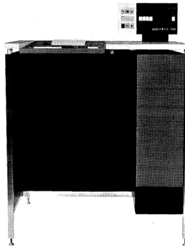
Another comm'UIlication medium between the operator and the central processor is the
Type 220 console, of which two versions are available. The Type 220-1 Console (Figure 1-2)
contains a typewriter which may be used as a peripheral device, operating under program control.
or as a logging typewriter by which the operator can make essential notes about the program in
progress. The central processor control panel remains situated on the processor cabinetry and
is used for the functions described above.
In the Type 220-3 Console (Figure 1-3), most of the co~trol panel functions, including that of direct access to the processor, are performed by means of the console typewriter. In addition,
the typewriter can perform the peripheral and logging functions described for the Type 220-1.
The central processor control panel is replaced by a smaller control panel containing only the
main power switches, the SENSE switches, and certain check condition indicators which are
located in the bottom row of the control panel shown in Figure 1,:", 1. The Type 220 -3 control
panel contains additional indicators used with the Storage Protect Feature (see page 1-23) and
Figure 1-2. Type 220-1 Console Figure 1-3. Type 220-3 Console
STANDARD PROCESSING MODE
The central proces sor performs arithmetic and logical operations as directed by the
in-structions of an internally stored program. These inin-structions are read into memory from an
input medium such as punched cards, magnetic tape, or punched paper tape. Control circuitry
within the processor then selects, interprets, and executes these instructions. Normally, the
instructions are executed sequentially. Branch instructions are provided, however, which make
it possible to skip over a group of instructions or otherwise c.hange the sequence of the program.
INTERRUPT PROCESSING MODE
Sequential instruction execution is changed temporarily whenever the central proc~ssor is
interrupted. Anyone of four sources can "demand" access to the central processor by generating
an interrupt signal, which turns on a central proces sor interrupt indicator. Once an interrupt
indicator is detected as being on, a hardware response is made: information concerning the
cur-rent status of the processor (including the setting of the sequence register) is stored, and a
branch is made to a stored routine which identifies and services the demand. Thus, programmed
tests need not be made to detect the presence of an interrupt condition - the entire process of
detecting and responding to an interrupt signal is an automatic hardware function. After the
stored service routine has been executed, control is returned to the interrupted routine at the
point where the interruption occurred and the previous status is restored. Two kinds of
inter-rupts can occur in the system: external interinter-rupts and an internal interrupt. A detailed
descrip-tion of interrupt funcdescrip-tions and programming for interrupt processing is presented in Appendix D.
[image:17.620.357.537.47.286.2] [image:17.620.85.298.57.296.2]SECTION I. SERIES 200 COMPONENTS
External Interrupts
The three sources of external interrupts are:
1. Peripheral Control - The control connected to any Series 200 peripheral
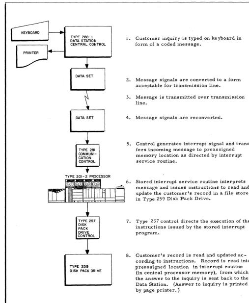
device can generate an interrupt signal under program control (peripheral controls are described on page 1-7; peripheral control interruption is described in Appendix D. For instance, a data communication control which services one or a number of communication lines and devices may generate a real-tim.e demand on central processor time to handle a cus-tomer inquiry from. a remote terminal. The current operation-s of the processor are temporarily interrupted so that the inquiry may be serviced. A routine to read the inquiry and to answer the question from. a stored customer file is autom.atically executed, and a response is sent back to the te rminal.
2. Operator's Control Panel or Console - The operator can interrupt the
central processor by pressing the INTERRUPT button on the control panel or console. 1 The source of such "on-site" interruptions is m.ade available to the program by the execution of a single instruction at the beginning of the interrupt service routine.
3. Program Instruction - One instruction in the Series 200 repertoire, the Monitor Call instruction, is used to generate an interrupt condition. 1 For programming convenience, the activation (or "calling") of the m.onitor program can be accomplished by means of this instruction o
Internal Interrupt
If a central processor contains the Storage Protect Feature (Types 1201, 1251, 2201, and
4201 only), an internal interrupt condition, caused by certain violations of a protected memory
area or attempts to address nonexistent m.emory locations, can also occur. Internal
interrup-tions are of lower priority than external interrupts, so that a processor executing an external
interrupt service routine does not respond to an internal interruption until the routine is
com-pleted. Processing of internal interrupts is described in Appendix Eo
ADDRESSING MODES
Due to the unique binary addressing system. used in referencing the individual core storage
locations within the central processor, an address portion of a machine-language instruction can
occupy two, three, or four characters of memory. The number of character positions employed
is controlled by two instructions: the assembly control instruction ADMODE, and the Change
Addressing Mode (CAM) instruction. Any core storage address can be referenced in any addre
ss-ing mode by havss-ing the central processor prefix the address expressed in the instruction with a
binary value previously set in an address register. Thus, the programmer has the ability to set
the address registers to some high module, switch to the two-character addressing mode, and
still continue to address that module. This utilization of the smallest num.ber of character
1
positions to expres s any core storage addres s results in a reduction in the amount of memory
required for a particular program.
ITEM-MARK TRAPPING MODE
The item-mark trapping mode, which can be set via the CAM instructIon, causes the
pro-cessor to treat and execute any instruction containing an item-marked op code as if it were a
Change Sequencing Mode (CSM) instruction, which results in a transfer of control to an
instruc-tion stored at a pre specified locainstruc-tion. This processing mode is used extensively in Liberator
systems and can also be used to control program branching.
PROCESSING POWER
The power of any processor within Series 200 can be defined as the sum of its main
mem-ory size, its internal speed, its degree of peripheral simultaneity, and the number of optional
feature s which may be added to it.
Main memory size within the Models 200/1200/1250/2200/4200 ranges from a minimum of
2, 048 character locations (Type s 201 and 201-1) to 524, 288 locations (Type 4201). Figure 1-4
shows the modular main memory sizes of the seven processor types.
The internal speed of a processor is measured in terms of a memory cycle (i. e., the time
required to read and restore the contents of a unit location). The unit location used by
proces-sors other than the Type 4201 is a single, six-bit character location. The unit location of the
Type 4201 is four successive character locations that contain a four-character word. Memory
cycle speeds range from two microseconds per character to 750 nanoseconds per four-character
word (see Figure 1-5).
Peripheral simultaneity is a key feature of Series 200 processors. Among the processors
described in this manual, from 3 (Model 200 processors) to 16 (Type 4201 processor)
simulta-neous input/ output operations can be performed concurrently with internal computing (see
Figure 1-6).
A number of optional features can be included in the Series 200 processors to provide
com-plete flexibility in specializing anyone proces sor to a user's particular application. Since some
of these features refer to the peripheral capabilities of a processor, they are sum.marized at the
conclusion of this section.
II
BASICII
OPTIONALSECTION I. SERIES 200 COMPONENTS
4201 1
220i
1250
1201
201-2
201-i
201
1
The Type 4201 moves four successive characters in 750 nanoseconds. Anyone of these characters is thereby moved in 188 nanoseconds.
Figure 1-5. Main Memory Speed
4201
2201
1251
1201
201-2
201-1
201
II
BASICI!!;~!~it
OPTIONALFigure 1-4. Main Mem.ory Size Figure 1-6. Peripheral Simultaneity (Number of Read/Write Channels Available to Processors)
PERIPHERAL EQUIPMENT
The array of peripheral device s available
with Series 200 processors includes over 40 units:
console typewriters, punched card equipment,
high-speed printers, magnetic tape units, paper
tape equipment, random access drum units, disk
devices, MICR reader-sorters, multiple tape listers, teller terminals, visual information
pro-jection units, and various data communication
controls and remote terminals. Also included
[image:20.621.39.547.59.511.2]ti:mer, a ti:me-of-day clock, and controls for optical source-docu:ment readers, optical journal
readers, digital plotters, and a bill feed printer.
Infor:m.ation is transferred between anyone of the se device s and the central proce s sor by
:means of a single stored-progra:m instruction - the Peripheral Data Transfer instruction
de-scribed in Section VIII. By coding various control characters in this instruction, the program:mer
.
specifies the direction of data transfer (into or out of the proces sor), the specific device involved
in the transfer, the data path over which information is to be transferred, and any other
infor-mation necessary to define the input/output operation (e. g., the nu:mber of lines to be spaced
during printer operations). The actual co:mmunication with the central processor is not made by
the particular peripheral device but by the peripheral control connected to that deviceo
PERIPHERAL CONTROL
A peripheral control regulates the transfer of data between a processor and a peripheral
device. The control compensates for the difference in the data transfer rates of the processor
and the peripheral device by temporarily storing each character of transmitted information until
either the processor or the device is ready to receive the character. The control also converts
each character into the code used by the intended recipient (e. g., the card reader control
con-verts a character fro:m Hollerith code to the internal six-bit code of the central processor). As
each character is transferred to the control, it is also checked for accuracy by the control. One
particularly significant feature of the peripheral control is that it operates independently of the
central processor and requires access to the main memory only when infor:mation transfers are
performed. In particular, all of the previously mentioned activities of the control - te:mporarily
storing, converting, and checking the information - do not involve the central processor in any
way. When each character of information is transferred, one :main :memory cycle is allocated
for the transfer.
So:me peripheral devices require one peripheral control per device (e. g., a card reader).
Other devices can be connected in :multiple fashion to a single peripheral control (e. g., up to
eight 1 /2-inch magnetic tape units can be directed by a single control). The number of Series
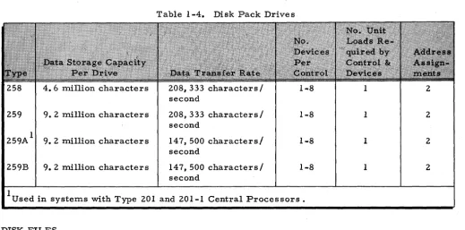
200 devices connectable to a peripheral control is shown in Tables 1-1 through 1-10 on the
fol-lowing pages. The infor:mation listed under "Unit Loads" and "Address Assign:ments" in these
tables is used in determining the nu:mber of peripheral controls that can be connected to a Series
200 processor, as explained on page 1-17.
PUNCHED CARD EQUIPMENT
Series 200 includes a wide variety of peripheral devices not only of different kinds, but'also
on several perfor:mance levels for the same kind. For instance, four different punched card units
SECTION I. SERIES 200 COMPONENTS
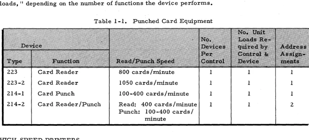
are offered: two card readers, a card punch, and one reader /punch. Table 1-1 lists the card
devices available within Series 200. Note that a card device requires either one or two "unit
loads, " depending on the number of functions the device performs.
Table 1-1. Punched Card Equipment
223 Card Reader 800 cards /minute 1 1 1
223-2 Card Reader 1050 cards /minute 1 1 1
214-1 Card Punch 100-400 cards/minute 1 1 1
214-2 Card Reader /Punch Read: 400 cards /rninute 1 1 2
Punch: 100-400 cards/ minute
HIGH-SPEED PRINTERS
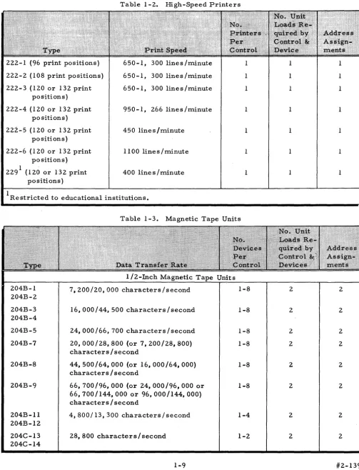
Six types of printers (see Table 1-2) produce printed reports, listings, etc., at speeds
which vary from 450 to 1,300 lines per minute. Processed information is .printed from any
pro-grammer-assigned area in memory. A single program instruction - the Move Character sand
Edit instruction - allows the programmer to punctuate the output date, suppress zeros, and
in-sert identifying symbols in the data prior to printing.
Print Buffer
With the addition of the Print Buffer (Feature 036), the amount of central processor
mem-ory cycles required for data transfer to the printer is reduced to less than
10/0.
Thus, more than990/0
of the central processor time is available for program execution. This feature is available only for the Type 222-3, -4, -5, and -6 Printers.MAGNETIC TAPE UNITS
Magnetic tape is a compact and highly versatile medium for the storage of programs and
data files. Two complete families of industry-acclaimed tape units are available with Series 200
processors (see Table 1-3): 1/2-inch tape units (10 types) transfer data at speeds ranging from
4,800 to 96,000 characters per second; three types of 3/4-inch tape units read/write from
32, 000 to 88, 800 characters per second. The capability of processing nine-track, 1 /2-inch tape
is also provided.
1200 BPI Recording Density
The l200-bits-per-inch recording density (Feature 054) provides the Type 204B-9
[image:22.623.36.543.101.331.2](bpi) on Dupont Crolyn magnetic tape. The 1200-bpi recording density enables the 204B-9 to
achieve a transfer rate of 144, 000 characters per second.
Table 1-2. High-Speed Printers
222-1 (96 print positions) 650-1, 300 lines /minute 1 1 1
222-2 (108 print positions) 650-1, 300 lines /minute 1 1 1
222-3 (120 or 132 print 650-1, 300 lines/minute 1 1
positions)
222-4 (120 or 132 print 950 -1, 266 lines/minute 1 1 1
positions)
222-5 (120 or 132 print 450 lines/minute 1 1 1
positions)
222-6 (120 or 132 print 1100 lines/minute 1 1 1
positions)
1 .
400 lines/minute
229 (120 or 132 print 1 1 1
positions)
lRestricted to educational institutions.
Table 1-3. Magnetic Tape Units
1 /2-Inch Magnetic Tape Units
204B-l 7,200/20,000 characters/second 1-8 2 2
204B-2
204B-3 16,000/44,500 characters/second 1-8 2 2
204B-4
204B-5 24,000/66,700 characters/second 1-8 2 2
204B-7 20, 000/28, 800 (or 7, 200/28, 800) 1-8 2 2
characters/second
204B-8 44, 500/64, 000 (or 16, 000/64, 000) 1-8 2 2
characters/second
204B-9 66, 700/96, 000 (or 24, 000/96, 000 or 1-8 2 2
66,700/144,000 or 96,000/144,000) characters/second
204B-ll 4,800/13,300 characters/second 1-4 2 2
204B-12
204C-13 28,800 characters/second 1-2 2 2
204C-14
[image:23.618.73.577.108.766.2] [image:23.618.77.579.111.376.2]