Malaysian Technical Universities International Conference on Engineering & Technology (MUiCET 201 1)
Analysis
of
Variable Dielectric Substrate
Thickness
of
X-Band Square Patch Reflectarray
Antenna
Noor Hafizah Binti ~ulaiman' and Muhammad Yusof Bin 1smail'
1
Radio Comnlunications and Antenna Design (RACAD) Department of Communication Engineering, Faculty of Electrical and Electronics Engineering,
Universiti Tun Hussein Onn Malaysia, 86400 Parit Raja, Johor, Malaysia
Abstract
The analysis of square patch reflectarray antenna with different thicknesses of dielectric substrate is presented. The substrate thickness is varied froin 1.41 h,to 1.46 h, in order to investigate the effect of scattering parameter behavior on the reflection loss and reflection phase of reflectarray antenna design. It has been observed that by increasing the thiclcness of dielectric substrate, the improvement of bandwidth performance from 126.5 MHz to 635.4 MHz is achieved. The reflection loss is also reduced from 1.322dB to 0.144dB when the different thickness of dielectric substrate is varied from 0.381mm to 1.570mm. The maximum bandwidth performance of the different thicknesses used is obtained by using 1.570mm which offers the highest bandwidth of 635.4 MHz with the lowest reflection loss of 0.144dB. By increasing the thickness of dielectric substrate, 509 MHz improvement in the bandwidth performance is obtained. The performance of the antenna design based on the characteristics of reflection loss, reflection phase and Figure of Merit (FoM) for different thicknesses of dielectric material are discussed in this paper.
ICeywords: Reflectarray antenna, variable thicknesses of dielectric substrate, enhanced bandwidth
Reflectarray antenna has been developed over 20 years ago which provides a mature technology for communication engineering particularly. The flat reflecting structure of the reflectarray also lends itself for flush mounting onto an existing flat structure without adding significant amount of mass and volume to the overall system structure [I]. The reflectarray antenna manufactured on a planar substrate printed circuit technology and offers the possibility of beam steering as phased arrays [2]. The reflection loss depends on the material properties of the dielectric material employed for the design as well as the thickness of the dielectric material. The feed antenna bandwidth and element spacing also limit the
bandwidth of reflectarrays but these two are not serious concerns if the bandwidth requirement is less than 15% [2].The purpose of this paper is to present the analysis reflectarray antenna by using variable
dielectric substrate thiclcness with bandwidth
improvements.
Malaysian Technical Universities International Confere~~ce on Engineering & Technology (MUiCET 201 1)
become more important in antenna designs [4]. Despite of many advantages the reflectarray antenna has limited use due to the possibility of higher loss and narrow bandwidth performance. The possibility of high loss is due to the dielectric loss, conductor loss and scattered loss which is introduced by surface wave excitation while the bandwidth performance of reflectarray antenna was mainly limited due to the differential spatial phase delays and its element [5]. Therefore the two factor of loss is conductor and the dielectric materials are much more significant. The reflection loss of the reflectarray antenna is primarily limited to dielectric absorption in the dielectric layer. The conductor loss depends upon the conductivity of conducting material for the patch element [6]. The configuration of absorption in the dielectric layer of reflectarray antenna is shown in Fig. 1.
.C-l=-F1-1-
Port E-xcitat~on (Incident Ftelds)ielectric Substrate
ltiple Bounces
Ground Plane
Fig. 1 Dielectric absorption in dielectric layer of reflectarray
As depicted in Fig.1, it is shown that the incident fields which is consumed from microwave energy of
reflectarray antenna and the losses due to
electromagnetic energy absorption caused by the multiple bounces in the dielectric substrate [7]. For thin dielectric substrate, inultiple bounces will occur in the dielectric substrate which contributes the high loss and narrow bandwidth performance. The absorption energy can be reduced by increasing thickness of dielectric substrate (h) hence decrease the number of bounces in the substrate region. By decreasing number of bounces in the region, the absorption of electromagnetic as well as the reflection loss can be reduced. The reflected field from microwave energy consists of scattered energy fioin the patch element and reflected energy froin the ground plane [8]. Maximum electric fields in reflectarray antenna are required to obtain maximum reflected signal. The
reflection loss
(RC)
can be given by equation (1).Where,
a,
andac
are the attenuation due to dielectricsubstrate and conductor loss respectively. The attenuation in dielectric substrate depends on the material properties [8]. The ideal value of reflection
loss for reflectarray antenna is 0 dB at resonant
frequency.
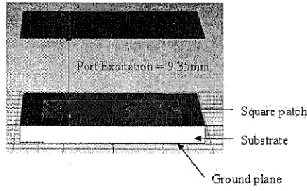
In order to study the effect of different thicknesses of dielectric substrate, an X band square patch reflectarray
antenna was designed to operate at 10 GHz. The
configuration of the square patch reflectarray antenna is shown in Fig.2.
\
Ground planeFig. 2 Configuration of square patch element reflectarray antenna
In this work, commercially available CST computer inodel has been used to inodel a unit cell element with proper boundary conditions. Square patch reflectarray antenna was constructed from dielectric substrate (h),
ground plane, patch element (L=l l imn x W=l 1 m ~ n )
with port distance excitation (t). In this investigation, the thicknesses of dielectric substrate have been varied
from 0.381 min to 1.570 mm. The dimension of
substrate for this square patch (d= 15 lm x 15 inm)
has been calculated by using equation (2).
A
d l "
2
Where
A,
is free space wavelength and Vo is speed oflight in free space, 3 x lo8 mdL. The width (W) and
Length (L) of patch have been calculated by using
equations (3) and (4).
WhereJ. is resonant frequency which is designed at
10 GHz and cr is dielectric constant, E, =2.2 has been
[image:2.530.282.501.210.346.2] [image:2.530.32.256.289.400.2]Malaysian Tecl~nical Universities International Cot~ference on Engineering Gr. Technology (MUiCET 201 1)
calculation of port excitation distance ( t ) to patch Reflection Phase for Variable Dielectric Substrate Thickness
element is based on equation (5).
180
.
a
t
=g+h+0.035
(5) 1204
-
80
B
The distance of port excitation from microwave
j
energy to patch element can be calculated by using
equation (6). { 4 0
LZ
a0
-120
ag
=- (6)&
-180 hoquenoy (Wz)1
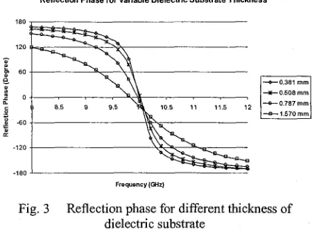
Fig. 3 Reflection phase for different thickness of
' r e f f =
2
2
(7) dielectric substrateAs depicted in Fig. 3, the 1.570 mm thickness
dielectric s~~bstrate (h) is gentler compared to the
Where h can be defined as thickness of substrate and
others thicknesses of substrate. The reflection phase
w is width of substrate.
curve is shown to be much gentler as the thickness of dielectric substrate was increased from 0.381 mm to
B. BAND WIDTH PERFORMANCE 1.570 mm. Figure of Merit (FoM) has been calculated
Generally the bandwidth performance of reflectarray and the result is shown in Table 1.
antenna can be analyzed by the reflection loss and
Table Results of figure of merit reflection phase curves. Bandwidth of reflectarray
antenna can be measured by using the reflection loss
curves. The 10 % and 20 % bandwidth are ineasured
by moving 10 % and 20 % above the reflection loss at
10 GHz. The bandwidth performance of the reflectarray can also be observed by the reflection
phase curve [ 9 ] . The bandwidth is calculated based on
the slope of the phase curve which can be represented ~ ~1 shows the ~i~~~~ of ~~~i~ ( F ~ M ) b l ~ vvith
using Figure of Merit (FoM) and static linear phase varying thiclaess of substrate. From the Table 1, it can
range- merit can be by using be seen that the 0.381 mm of dielectric substrate offers
equation (8). of 0.374 O/MHZ FoM compared with 1.570 mm
dielectric substrate which offers of 0.1 10 O/MHZ FoM.
A 4
FoM
=-
(OIMHZ) (8) The lowest value of FoM is shown offered the highestA f
bandwidth performance in reflectarray antenna.Refleclion Loss With Variable Dielectric Substrate Thickness
Where
A 4
is the change in the reflection phase in Odegrees and
Af
is the change in the resonant frequency-0.2
in MHz of the reflectarray antenna. FoM is calculated
in O/MHZ. -0.4
C
B
-0.6 -0.381 m m
J -0 508 m m
4. RESULTS AND ANALYSIS g : -0.8 -%-0.787
-
m m1.570 m m
=
A simulation model of square patch reflectarray
antenna was designed by using cominercially available
yl::
:
computer software CST MWS. In this study the
reflection phase curve for variable thickness dielectric 8 8.5 8 9.5 10 10.5 11 11.5 12
Frequsnsy (GHz)
substrate has been plotted in Fig. 3.
[image:3.530.269.499.60.227.2] [image:3.530.270.491.359.431.2] [image:3.530.274.496.550.695.2]Malaysian Technical Universities International Conference on Engineering & Technology (MUiCET 201 1)
[image:4.525.31.265.213.309.2]Fig. 4 shows the reflection loss curve for variable thickness of dielectric substrate from 0.381 inin to 1.570 inm. It can be seen that the 0.381 imn of dielectric substrate ( h ) gives the highest loss of 1.322 dB compared with 1.570 inin dielectric substrate (h) which only offers 0.144 dB of reflection loss. From these results, it is proven that the thickest substrate of dielectric material offers low of reflection loss performance.
Table 2: Results of reflection loss and bandwidth performance
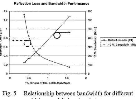
Table 2 shows the results of reflection loss and bandwidth performance. It can be seen that for thickness of dielectric substrate ( h ) 0.381 inin, 10 % of bandwidth only offers 126.4 MHz while the 1.570 imn offers broader bandwidth perforinance of 635.4 MHz. It can be observed that the bandwidth perforinance of 509MHz is achieved. The relationship between variable thicknesses of dielectric substrate and bandwidth perforinance is shown in Fig. 5.
Thickness, h (inm) 0.381 0.508 0.787 1.570
Reflection Loss and Bandwidth Performance
E 1 - \ / - so0 p
9 B
8 0.0 -
J 4 - -
6
g 0.6 -- - 300 5 % Bandwidth (MHz)
-
Reflection Loss (dB) -1.322 -0.825 -0.41 1 -0.144Fig. 5 Relationship between bandwidth for different thickness of dielectric substrate
Fig. 5 shows the relationship between reflection loss and bandwidth perforinance. By increasing thickness of dielectric substrate, the bandwidth is shown to be increased from 126.4 MHz to 635.4 MHz whereas reflection loss is observed to decrease gradually from 1.322 dB to 0.144 dB. The reflection loss has been reducing by increasing thickness of dielectric substrate. It is because of the thickness of dielectric substrate which reduces the energy absorption in dielectric layer. From Fig. 5, it can be observed that
10 %
Bandwidth (MHz) 126.4 171.5 277.4 635.4
the reflection loss is inversely proportional to the bandwidth perforinance. From this result, it is shown that the thickness of dielectric material can be used to achieve lowest reflection loss with enhance bandwidth perforinance.
20 %
Bandwidth (MHz) 186.7 256.3 416.8 952.8
The results obtained in this work demonstrate that the dielectric substrate plays a crucial role in determining the bandwidth performance of reflectarray antenna. The effects of substrate thicknesses on the
reflectarray antenna performance have been
demonstrated for substrate thickness ranging from 0.38 linm to 1.570inin. Further investigations are required to be done particularly the experimental verifications in order to validate the simulated results from CST computer model.
ACKNOWLEDGMENT
This research work is fully funded by Fundamental Research Grant Scheme (FRGS) (VOT 0718), Ministry of Higher Education, Malaysia. We would like to thank the staff of Radio Coininunications and Antenna Design (RACAD) Laboratory of Universiti Tun Hussein Onn Malaysia (UTHM) for the technical support.
REFERENCES
[I] J. Huang and J. A. Encinar, Reflectarray Antenna.
New Jersey, 2008.
[2] J.A. Encinar, "Analysis, Design and Applications
of Reflectarrays," !Z7 Iberian Meeting on
Conzputational Electromagnetics, 2008
[3] D.G. Berry, R.G Malech and W.A. Kennedy, "The Reflectarray Antenna," IEEE Trans Antennas Propagate. Vol. AP-11. pp. 645-651. 1963.
[4] K.Y Sze, and L. Shafal, "Analysis of Phase
Variation Due To Varying Patch Length In A Microstrip Reflectarray." IEEE Trans. Vol. 2. 1998.
[5] H. Rajagopalan and Y.R. Sainii, "On The
Reflection Characteristic of a Reflectarray
Element with Low-Loss and High- Loss
Substrates.,"IEEE Antennas and Propagation Magazine, Vol. 52, No.4, Aug. 2010.
[6] S.J. Fiedziuszko, L.Tatsuo, Yoshio Icobayashi, Toshio Nishikawa, Steven N. Stitzer, I(ikuo Waltino. "Dielectric Materials, Devices, and Circuits," IEEE Transactions on Microwave Theovy and Techniques, Vol. 50, No. 3,2002. [7] C.A. Balanis, Antenna Theory, 2'ld Edition, New
York: Wiley Press, 1982.
[image:4.525.41.259.455.614.2]Malaysian Technical Universities International Conference on Engineering & Technology (MUiCET 201 1)
[9] M.Y.Ismai1 and M.Inam. "Analysis of Design Optimization of Bandwidth and Loss Performance of Reflectarray Antennas Based on Material Properties," Modern Applied Science J. CCSE.