A Modular Platform for Optimised and Green Sensing
Applications Development Using Dedicated
Microelectronic ICs and Embedded Data Processing
Riad Kanan
University of Applied Science, HES-SO, 1950 Sion, Switzerland Abu Dhabi University, CECS, P.O. Box 59911, Abu Dhabi, UAE
*Corresponding Author: [email protected]
Copyright © 2013 Horizon Research Publishing All rights reserved.
Abstract
This paper presents a modular platform allowing green sensing applications. It is composed of a dedicated Integrated Circuit (IC) with energy harvesting system, sensors, rechargeable battery, a processor and a memory. A sensing system has been designed. It comprises the modular transponder platform, a transceiver with advanced communication features and user applications. The sensing system acts as a smart miniaturized system with multi-functions feature and is a key to achieve different application in the sensing and monitoring field. Thanks to the Layered HW/Firmware/SW system structure, the smart sensing platform offers the possibility to extend application domains. One of the key impacts of the system is the development of green applications. The new developed energy harvesting system leads to a self-powered system which is a new benefit in the sensing and continuous monitoring. Using rechargeable battery and energy harvesting systems will prevent often discarding away old batteries. Furthermore, thanks to the embedded data processing, the sensing platform allows the development of environment-sensitive applications such as shelf life prediction that can help to reduce food losses.Keywords
Sensing System, Conditions Monitoring, Energy Harvesting, Multi-Protocol1. Introduction
In recent years, RFID (Radio Frequency Identification) has been introduced in sensing applications and semi-passive RFID transponders (tags) are mainly used for such applications. The battery of semi-passive RFID is only used to power the sensor and recording logic.
New developments in recent years have provided solutions for temperature monitoring, but RFID for sensing applications is still limited to sensing and storing the
temperature and fulfilling the functionality of data logger. Data-loggers offer an economical solution for the spatial profiling of transports with a high number of data-loggers [1,2].
In order to handle the data for a high number of temperature records, the measurements have to be processed locally. It is not feasible to transmit full temperature data by a transceiver (RFID reader) at unloading of a truck or container [3].
For higher accuracy, the system should process sensors’ data and provide the important information such as for example the shelf life prediction and an estimation of the time-delayed core temperature by surface measurements for environment-sensitive applications [4].
The proposed RFID modular platform allows the development of new applications by using a freely programmable processor. A Layered HW/Firmware/SW system structure provides an easy update and offers the possibility to extend application domains. In addition, the platform allows the use of different sensors. The number of sensors to be added will depend on the target application and the number of environmental condition parameters to monitor.
Currently, wireless sensing projects, focus on creating RFID-enabled sensors that are read using RFID transceivers and data transferred to a desktop computer for analysis. However, the goal of this design is to go further beyond the existing solutions and create an easy-to-use solution for collating sensor information, and if necessary transmitting them to a device for analysis. Once on the device, the sensor data will be visualized, and the user will be able to scale, zoom and scroll the visualization to easily navigate to points of failure and view the details of a potential problem.
Given the mentioned, users do not need to have a sophisticated knowledge of advanced formalisms or technologies; the high usability of the system is achieved by high comfort of the user-system interaction.
of green applications. Indeed, in wireless sensing systems, batteries have a finite life time and energy depletion often occurs within few months. Using rechargeable battery and energy harvesting systems will prevent often discarding away old batteries. The new developed energy harvesting system leads to a self-powered system which is a new benefit in the sensing and continuous monitoring.
In addition, the efficient use of the RFID transponder system is needed to prolong battery lifetime. Therefore, different strategies to achieve maximal autonomy time for the RFID transponder have been adopted.
The paper is organized as follows. In the next Section 2, we describe the proposed sensing system. Section 3 presents the developed innovative technologies. In Section 4 we describe different hardware components of the system. Section 5 presents the user interface. Finally, we present a conclusion of the work in Section 6.
2. System Description
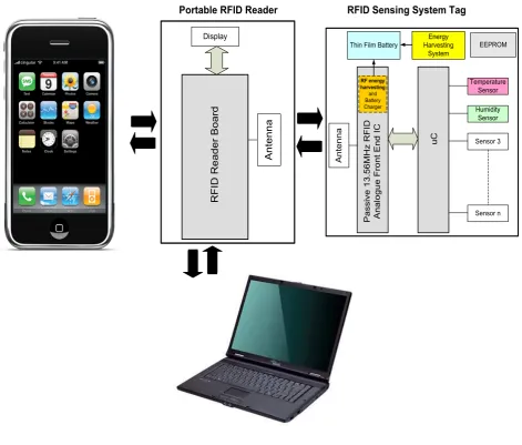
This project took forward the development of a Smart RFID system which comprises (Figure 1):
Modular Transponder platform (RFID Sensing System Tag) for environmental conditions monitoring, data storing, energy harvesting, and application processing.
RFID Transceiver to get from the transponder the application information, and the history of environmental conditions. The transceiver has a wired and wireless connection to a PC and a mobile phone. In addition, if urgent analysis is required and no mobile phone or PC is present, a GSM module is integrated in the transceiver to allow the transmission of data to central database.
[image:2.595.77.549.311.712.2]User applications for further analysis
Figure 1. Schematic diagram of the RFID sensing system
Portable RFID Reader RFID Sensing System Tag
RFID Reader Board
Display
Antenna
Passive
13
.56
MHz RFID
Analogue Front End IC
uC
Temperature Sensor
Humidity Sensor
Sensor 3
Sensor n Thin Film Battery
RF energy harvesting
and Battery Charger
Energy Harvesting
System
Antenna
The smart monitoring system will be used according to the following scenarios:
a). As a knowledge-led decision support instrument: The Smart transponders attached to items, cases, or pallets monitor, log, and process the environmental condition measurement at predefined intervals during transportation or product lifecycle.
At each transshipment point, the system will provide the necessary information for management, which is the shelf life prediction based on the used quality model. The information on the shipment quality and safety aspect will be then used to make appropriate managerial decisions that maintain and increase the value across a supply chain. If there is a potential problem with the shipment, it needs then to be managed carefully and efficiently to prevent loss and conflicts with delivery commitments.
When arrived at the final destination, the transponders will be prepared in order to be re-used for tracking another product. Furthermore, the battery level will be checked. The newly developed energy harvesting system is used then to re-charge the battery in case of energy depletion. In addition, for this new mission, the transceiver will transmit to the transponders the specific quality model parameters of the new product to be shipped. Subsequently, monitoring, logging, and processing will restart.
b) As a knowledge-led transport logistic improvement instrument:
In order to improve the transport logistic by changing environmental conditions during the logistic chain, when a problem with a shipment is detected which indicates that an environment condition–time threshold was overstepped; the registered data will be analyzed to detect the position and time of the unacceptable conditions during shipment or storage.
c) As a knowledge-led traceability instrument:
Besides environmental conditions logging capabilities and Shelf life time prediction, the sensing system enables automatic identification and tracking of individual products, cases, pallets and containers providing organizations with electronic documentation, automated track and trace capabilities, streamlined business workflow, and increased efficiencies.
A component-level research was carried out and a number of innovative technologies have been developed, applied and evaluated. These technologies consist in a multi-protocol RFID sensing transponder, an energy harvesting system, an RFID transponder with a freely programmable processor, an RFID transceiver with advanced communication features and user applications.
3. Technology
3.1. Operating Frequency
The RFID sensing system is developed for worldwide transportation. Therefore, the operating frequency and the protocol have been selected wisely.
The ISM (Industrial, Scientific, Medical) 13.56MHz band used worldwide is selected for communication. In addition, we provide a communication platform fully compliant with the standard NFC (Near Field Communication) and ISO15693 protocols and including the extension for sensing applications [5] [6] [7].
3.2. Multi-protocol Transponder
In RFID communication systems, the transponder is always designed to be compliant with one standard protocol. On the other hand, the transceiver can process one or more communication standards due to its processing unit.
In the proposed system, we provide a multi-protocol transponder which is able to identify the communication protocol and respond to the transceiver using the same standard protocol.
Multi-protocol transponder is relevant for future designs, when the emerging of NFC which will bring RFID technology to mobile handsets.
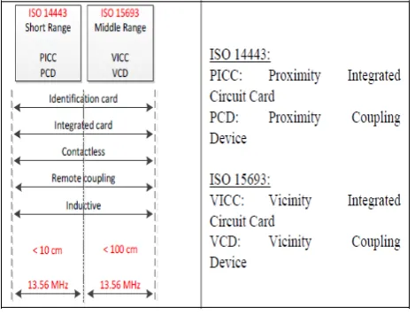
In addition, the multi-protocol communication capability allows the transponder to be readable with any 13.56 MHz compatible RFID transceiver.
Figure 2 shows an overview of the RFID standards compatible with 13.56MHz.
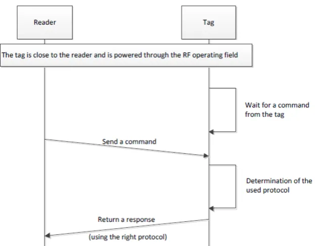
Considering a system with a single protocol, the transponder waits silently for a command from the transceiver, after being powered by the RF operating field. When a command is received, the transponder sends a response.
[image:3.595.316.551.544.722.2]In the proposed multi-protocol communication system, the initialization of the dialog is similar to that described above with one difference: the transponder has to decode the protocol used by the transceiver before sending a response using the right protocol (Figure 3).
Figure 3. Initialization of the communication with a multi-protocol system
4. Hardware
4.1 RFID Sensing System Transponder
The transponder system is a semi-active element. Figure 4 shows the RFID transponder general architecture. The transponder is designed with the minimum electronics components and optimized to achieve a low current consumption during operating period. It is composed of a dedicated passive RFID Analogue Front End (AFE) Integrated Circuit (IC), environmental monitoring sensors, a microcontroller used for new applications development and sensors data analysis, and a EEPROM memory needed for sensors data storing.
To allow the application extension using freely programmable processor, a new passive RFID chip has been designed and fabricated successfully using a 0.35um CMOS technology (Figure 5). The purpose of the new chip is the communication. It acts as a bridge between the transceiver and the transponder system. It transmits to the transceiver the stored data and a real time sensor measures through the RF Field (Figure 1).
(a)
[image:4.595.329.539.357.516.2](b)
Figure 4. (a) RFID transponder general architecture system, (b) RFID transponder system
[image:4.595.338.524.553.724.2]The component list is summarized in Table 1. Table 1. Component list
Component Model Notes
Microcontroller MSP430F2350IRHA 256KB RAM 16KB Flash, Sensor SHT11 Temp & Humidity EEPROM 24LC256-I/SM 256KB Regulator TPS78233
AFE Proprietary 13.56MHz RFID Analogue Front End
4.2. Battery Charger
The important feature of the proposed system is the re-use feature thanks to the battery charger block which will allow re-charging the battery through the RF field. The battery charger has been designed to allow the charging of a
Micro-Energy Cell (MEC®) which is a solid-state, rechargeable thin-film battery. MECs are manufactured by Infinite Power Solutions [8] using wide area thin-film deposition techniques similar to those used to manufacture semiconductors. The MEC enjoy the advantages of rapid recharge and charge acceptance at currents as low as 1uA.
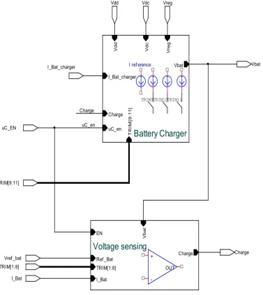
[image:5.595.120.498.315.738.2]Figure 6 shows the block diagram of the battery charger. It consists of a battery current charger and a voltage sensing blocks. The battery supply (Vdc) is obtained using a rectifier which converts the power carrier of the wireless link to a DC voltage. The battery current charger consists of reference current and current sources. The voltage sensing block senses the battery voltage and generates the end-of-charge signal (Charge) so the microcontroller will set the Enable (uc_EN) low to stop the battery charging. The selection of the current charge level and the battery end-of-charge is done by a trimming method. The trimming circuit was chosen by means of a binary weighted switch network with 11 bits resolution.
Figure 6. Block diagram of the battery charger
Vdd
Charge
TRIM[1:8]
Vdc
uC_en
Vreg
TRIM[9:11]
Vbat
Vref _bat
Battery Charger
V
dc
I_Bat_charger
Vbat
Charge
TRI
M[
9
:1
1
]
uC_en
Vreg
V
dd
Voltage sensing
I_Bat
V
ba
t
Ref _Bat Charge
EN
TRIM[1:8]
Charge
I_Bat
I_Bat_charger
uC_EN
I ref erence
TRIM11 TRIM10 TRIM9
+
4.3. Transponder Optimized Power Consumption Consideration
The transponder system is optimized for low-power dissipation in order to extend the battery lifetime and to prevent the energy depletion during the transport. To prepare the transponders for a new shipment, a new battery charging cycle will be initiated.
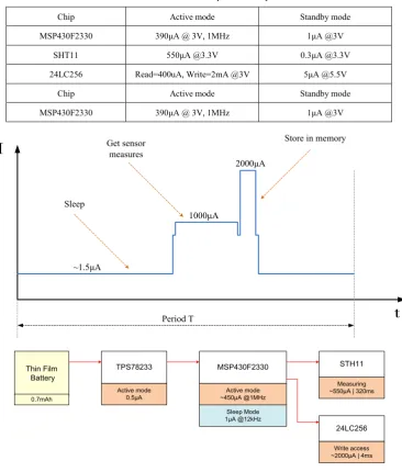
Table 2 summarizes the power consumption of each component of the transponder.
By using the duty-cycling approach, the transponder components are used efficiently, i.e. the sensor is active during a short period and goes to the standby mode when the sensing data are sent or stored in the EEPROM. The EEPROM is switched to the standby mode after a write cycle.
[image:6.595.123.490.209.640.2]Figure 7 presents the current consumption at different operating steps of the transponder during one sampling period.
Table 2. Power consumption summary
Chip Active mode Standby mode
MSP430F2330 390μA @ 3V, 1MHz 1μA @3V
SHT11 550μA @3.3V 0.3μA @3.3V
24LC256 Read=400uA, Write=2mA @3V 5μA @5.5V
Chip Active mode Standby mode
MSP430F2330 390μA @ 3V, 1MHz 1μA @3V
Figure 7. Current consumption at different transponder operating steps
From Figure 7, the average current/Period (T) can be given by (1):
(1) For a battery with 0.7mAh capacity, the battery lifetime is then given by (2):
I
t
1000μA
~1.5μA
2000μA
Period T Sleep
Get sensor measures
Store in memory
MSP430F2330 TPS78233
Thin Film Battery
STH11
24LC256
Active mode ~450μA @1MHz
Sleep Mode 1μA @12kHz Active mode
0.5μA 0.7mAh
Measuring ~550μA | 320ms
Write access ~2000μA | 4ms
T
uA
ms
T
ms
uA
ms
uA
(2)
Figure 8. Battery lifetime as function of the sampling period
Figure 8 presents the battery lifetime for different battery capacity as function of the sampling period. As example, when a measurement period is set to 10 minutes, a battery with a capacity of 1mAh can be used for about 20 days before starting a new battery charging cycle. A small battery capacity is selected to get a thin form factor for the overall transponder.
4.4. RFID Transceiver
There exist several technologies used for establishing communication between a mobile RFID transceiver and a Collection Data System (Central Database) or Visualization Systems. Generally, they are divided into wired and wireless. The most popular wired ones are RS485, RS422, RS232, CAN, Ethernet, or USB standard. Wireless has a wider spread of technologies: Bluetooth, WiFi, GSM, NFC, and dedicated closed architecture industrial radio standards. Wired and wireless technologies can provide transmission speeds between 424kbps (NFC) to more than 400Mbps (USB). One of the factors influencing the choice of the particular technology is the physical distance between RFID transceiver and Database/Visualization Systems. For few meters communication, the system can be wired (USB cable), whereas for thousands of kilometers, it must be wireless (e.g. GSM standard). The idea of a mobile RFID transceiver is to combine a transceiver and a transmission device (wired or wireless) into a single device, which proves helpful in use-cases and applications, such as warehouse and package tracking of items with specific features.
Currently, wireless sensing projects focus on creating
RFID-enabled sensors that are used for gathering data input to RFID transceivers. The data is usually transferred to a PC for analysis or forwarded to a database.
However, the goal this design was to go further beyond existing solutions and create an easy-to-use solution for collating sensor information from RFID transponders in warehouses or during transportation, and provide connectivity solutions for transferring data/information by various technologies to other devices like PCs and mobile phones for data analyzing, viewing, or storing on database servers. Warehouses can use these RFID transponders and a RFID transceiver with Bluetooth/WiFi/GSM extensions to gather, analyze, visualize, and store the data on database servers. Additionally, USB provides a wired interface for transmission and charging.
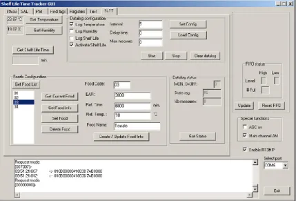
5. User Interface
Based on geographic and various interpretive functionalities, different modes of sensor and tracking data display were investigated. The needs require displaying appropriately, multiple sensors, historical data, different quality model parameters, and predictions.
User applications on PC (Figure 9) and smart mobile phone with an easy to use interface for a graphical display of sensor data have been implemented. They can be extended to include multiple sensors, quality model parameters inputs, historical data. In addition, a web user support application has been designed.
avg
time
uA
I
s
W
=
700
•
3600
2 4 6 8 10 12 14 16 18 20 22 24 26 28 30
2 5 7 9 12 14 16 19 21 23 25
Sampling period, min
W
or
ki
ng t
im
e,
day
s
Tag working time
Figure 9. Graphical User Interface
6. Conclusion
In this paper, a novel modular sensing platform validated in a Smart, Self-powered, Low-cost and Re-usable system was presented.
The proposed system allows the development of environment-sensitive applications and supports the supply chain partners in monitoring quality changes during transport of perishable foods, meat, medicines, pharmaceuticals, and other goods which are sensitive to the environmental conditions.
Acknowledgements
This work has been supported by the HES-SO (Project No. 21958). The authors would like to thank the RCSO ISYS scientific committee.
REFERENCES
[1] R. Marco, P. S. Luciano, S. Alberto. Performances of time-temperature indicators in the study of temperature exposure of packaged fresh foods, Packaging Technology and Science 14 (1), 1–39, 2001.
[2] S. Burgess. Measurement, Analysis, and Comparison of the Parcel Shipping Shock and Drop Environment of the United States Postal Service with Commercial Carriers. JOTE 35 (3), JTE100787, 2007.
[3] R. Jedermann, W. Lang. The minimum number of sensors- Interpolation of spatial temperature profiles, Wireless Sensor Networks, 6th European Conference, Vol. 5432, pp. 232-246, , 2009.
[4] R. Jedermann. J.P. Edmond. W. Lang. Shelf life prediction by intelligent RFID, Dynamics in Logistics. First International Conference, pp. 231-238, 2007.
[5] ISO/IEC 15693-2. Radio frequency power and signal interface.
[6] ISO/IEC 14443-2. Radio frequency power and signal interface.
[7] ISO/IEC 14443-3. Initialization and anti-collision.