International Journal of Emerging Technology and Advanced Engineering
Website: www.ijetae.com (ISSN 2250-2459,ISO 9001:2008 Certified Journal, Volume 5, Issue 5, May 2015)
90
Semi-Automated Wall-Care Machine
Swapnil Ashok Sadalagi
1, Rohan Sudhir Bhore
2, Soumil Nayan Jagani
3, Tilu Vishnu Parab
4,
Anand C. Mattikalli.
51,2,3,4Student, Mechanical Department, MMEC, Belgavi. 5
Asst. Prof. Mechanical Department, MMEC, Belgavi.
Abstract— Today’s developing world is always in the
need for new developing ideas to help make work easy and fast. This paper proposal is related to the construction field which relates to our project. Construction of buildings both residential and workplaces are also requiring new ideas to boost their work by using automated and semi-automated ideas which help do manual work in a faster and efficient way. So to prove helpful to the construction industry we have made a workable semi-automated wall-care (putty) machine which helps apply the wall-care in an efficient and faster way as compared to the existing manual method. This project prototype includes- Design, development, fabrication, testing and analysis as well as experimental work. This will improve the quality and the kind of conventional machinery and procedures used to plaster walls. The machine is semi-automated and makes use of day to day practices about plastering and wall surfaces.
Keywords— Construction Equipment, Putty, Plaster, Semi Automated Wallcare Machine, Wallcare.
I. INTRODUCTION
This project is a welcome edition and a new innovative concept where we thought this as an ideal alternative for the manual method. This Project relates to the design and fabrication of semi-automatic wall care machine. This project will not only provide an alternative to manual labour used but also with high efficiency and portability. India is a growing economy and the infrastructure in the nation is developing day by day, thus improvements and new methodology is always into process. Besides being used to ancient methods the people are increasingly finding new methods and ways to make their homes more decorative and attractive. The application of paints on the interior as well as exterior has become a necessity and for this applying wallcare on the wall structure has become important thus, new and faster ways to apply the wallcare efficiently are found out. We then visited the market to scout for various alternatives for the same but found none; hence we decided to manufacture our own machine.
II. OBJECTIVE
To design and develop a machine for application of wall care (putty) by fabricating, testing, improving, analysis as well as experimental work.
III. EXISTING SYSTEM
Currently there is no machinery that is used to apply wall-care on wall surfaces which exists in India. The wall-care is currently applied on the walls manually by labourers using a wall-care plate directly on the wall by hand. The wall-care is spread over a unit area by applying pressure on the plate until a uniform layer is obtained.
IV. METHODS
The methodology to create a prototype of the project,
• Observation and analysis of the conventional
methods used to plaster walls.
• Market survey about any existing tools, equipment
and machineries.
• Analysis about the existing methodology.
• To improve existing methods.
• Methods to tackle the disadvantages in the current
methods.
• Design of machine (line diagram).
• Design analysis and improvement under the
guidance of expertise
• Experimental analysis of the machine.
•
Elimination of the errors using trial and errormethod.
V. IDEA
CurrentlyOn the analysis phase this project has been
developed after visiting various construction sites in and around our locality and college premises. We analysed the current manual method of applying wall-care on the walls. Thus we decided to improvise the method by making it cost effective and time saving.
On experimental side, we made a scaled down version of the blade arrangement and tested in our local compound .After finding the idea workable we decided to make a prototype making it user friendly and
semi-automated
.
VI. PARTS
International Journal of Emerging Technology and Advanced Engineering
Website: www.ijetae.com (ISSN 2250-2459,ISO 9001:2008 Certified Journal, Volume 5, Issue 5, May 2015)
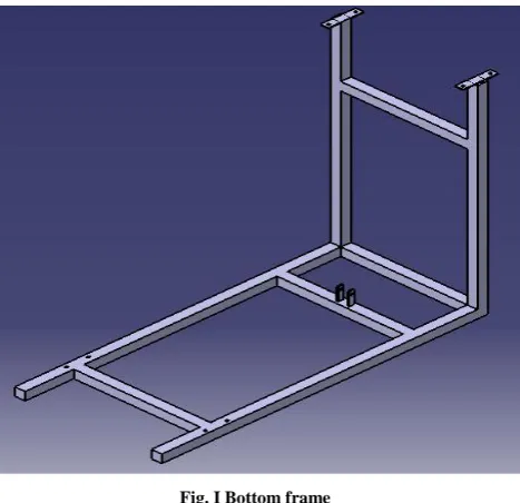
[image:2.595.49.283.133.359.2]91
Fig. I Bottom frame• Top Frame-It transfers the load to the columns when the handwheel is rotated. It also contains the pulleys over which the rope moves.
Fig. II Top Frame
• Box With Blade Attachment Frame-This box
[image:2.595.316.546.209.344.2]contains the wall-care mixture. A blade frame arrangement is made as shown in figure in which inclination of the individual blades can be adjusted manually.
Fig. III Box with Blade attachment
[image:2.595.49.285.406.557.2]• Push Rod –The push rod is made by attaching a metallic plate with rubber to the metal rod. On the other end a fixture is made with multiple holes to adjust the length of the pushrod after fixing it with the swivel. This push rod slides in and out inside the box and helps in pushing the wall-care outside the box through the slit provided on the other end.
Fig. IV Push rod
• Columns-The columns help in supporting the top frame and help in carrying the load of the box as well helps in allowing the box to slide over it. • Castor Wheels-These are provided at the bottom for
easy transportation.
• Pulleys-Help in lifting the load efficiently.
• Blades-The blades are attached to the blade frame. These blades have an adjustable inclination which is made possible with screws.
• Swivel Assembly-The swivel helps as support to the push rod and slides over the column giving the pushrod the strength to move inside the box.
• Handwheel Arrangement-The handwheel is used to
pull the box containing the wallcare upwards using the rope and pulley mechanism.
VII. ASSEMBLY
[image:2.595.48.285.615.762.2]International Journal of Emerging Technology and Advanced Engineering
Website: www.ijetae.com (ISSN 2250-2459,ISO 9001:2008 Certified Journal, Volume 5, Issue 5, May 2015)
[image:3.595.47.282.259.664.2]92
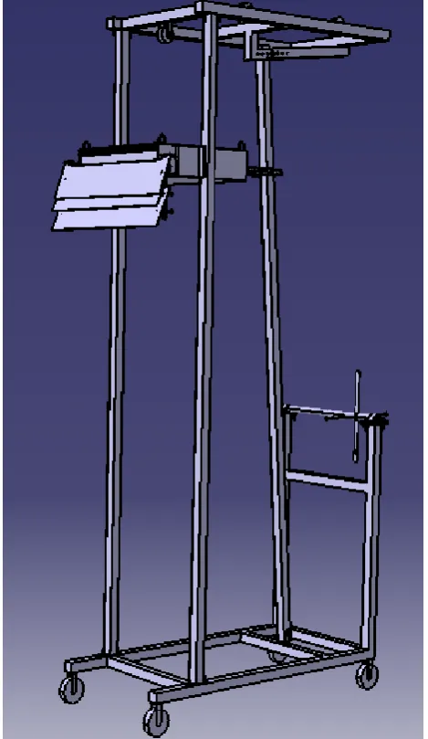
The main box in which the wall-care is to be poured has four hooks to hold it to the rope .This box is then connected to the rope using iron chains of equal lengths which meet at a common “s”-hook attached to the rope. The other end of the rope is then pulled over the pulley on the upper frames and tied to the handwheel assembly. There are four castor wheels provided at the bottom frame for easy transportation of the machine. Of these four wheels, two wheels are provided with a locking mechanism so as to fix the machine while operationFig. V Prototype Design of the Project
VIII. WORKING
The machine is clamped to the wall ensuring that the blade edges touch the wall surface evenly. The wall-care paste is then poured into the box of the machine which carries the wall-care paste. The inclined column is adjusted to the required inclination angle depending upon the amount of wall-care to be applied on the wall.
The box containing the wall-care paste is lowered to the required height. The user then rotates the Handwheel which helps in lifting the box using rope and pulley mechanism. Due to the upward movement of the box the push rod which slides on the inclined column tends to move inwards into the box. The push rod which has a plate and rubber pad at the other end inside the box keeps the box sealed and prevents leakage of the paste. Due to the inward motion of the push rod the pressure is acted upon the paste which moves out from the slit provided on the opposite side of the box, thus enabling the paste to fall on the blade surface. As the blades rest upon the wall surface the upward motion causes the wall-care to be pasted on the wall surface.
The arrangement of the three blades is made in such a way that the first blade just applies the wall care in a rough manner. The second blade is arranged in such a way that it applies more amount of pressure to apply the wall care uniformly over the wall surface. The third blade is inclined more so that the excess of wall care is removed from the wall surface.
Thus, a perfect wall-care layer is obtained which is comparable to the first coat obtained by the manual method.
After this process is completed the machine is pulled back from the wall and the box is lowered and the process is repeated again for applying the wall-care on the remaining part of the wall.
IX. ADVANTAGES
Time Saving
Cost Saving
Requires less floor area
Portable machine
External attachments for variable heights
Low maintainance
Easy to assemble and disassemble
Low investment cost
Easy to clean after use
X. DISADVANTAGES
Cannot be used for inclined or curved walls
Manually filling of wallcare paste(putty) is required
XI. ANALYSIS
Once the prototype model was made we put it on experimenting to eliminate the errors and other factors affecting the smooth functioning of the machine. We observed the amount and quality of wall care being applied on the wall. After some improvement we got the perfect coat (first coat) which had the same finish and
amount of putty as applied manually by
International Journal of Emerging Technology and Advanced Engineering
Website: www.ijetae.com (ISSN 2250-2459,ISO 9001:2008 Certified Journal, Volume 5, Issue 5, May 2015)
93
XII. FUTURE SCOPEThis prototype can be fully automated by using sensor, electric motor & different mechanisms, for smooth functioning of the machine.
XIII. CONCLUSION
The systematic approach in each and everything done in industries is of great revolution to us. We became part of a big system and we appreciated it. Design in current industry for application of wall care (putty) does not have any standards and it is all dependent on individual worker. We are providing them standards to become revolution in construction field.
Designing and fabrication involves various steps. Through study of these steps gave a great insight into the subject practically. It is our great achievement in our college life and we are proud to say so.
XIV. WORKING MODEL
The picture shown below is a working prototype of the idea of the project and is fully functional at this time.
International Journal of Emerging Technology and Advanced Engineering
Website: www.ijetae.com (ISSN 2250-2459,ISO 9001:2008 Certified Journal, Volume 5, Issue 5, May 2015)
94
REFERENCES[1] Mechanical Engineering Design By Ashok G.Ambekar, Phl Learning Pvt.Ltd.,2009
Chapter 1-Mechanism And Machines Chapter 12-Belt And Rope Drives [2] Machine Design By Robert L. Norton ,2nd Edition,Pearson
Education
Chapter 2-Bearings And Lubrication Chapter 2.6-General Properties Of Metals Chapter 1.7-Factor Of Safety Chapter 3.6-Dynamic Loading
Chapter 4-Stress Strain And Deflection
[3] Project Management By Harold Kerzner ,Cbs Publishersand Distributors, 2004
Chapter 14- Pricing And Distribution
[4] Mechanism And Machine Theory By Ashok G. Ambekar,Phl Learning Pvt Ltd.,2009
Chapter 3-Velocity And Acceleration Analysis Chapter 14-Dynamics Of Machines
[5] Industrial Engineering And Management By O.P. Khanna,Dhanpat Rai Publication,2013
Chapter 5-Product Design,Planning And Development
[6] Product Design For Manufacture And Assembly By Geoffrey Boothroyd,Peter Dewhurst,Winston A. Knight,Crc Press,2013 Chapter 2-Selection Of Material And Processes
Chapter 3-Product Design For Manual Assembly Chapter 7-Design For Machining
Chapter 8-Powder Metal Processing
[7] Strength Of Materials By James M. Gere,Barry J. Goodno,Cengage Learning, 2009
Chapter 1-Tension,Compression And Shear Chapter 2-Axially Loaded Members
Chapter 3-Torsion
Chapter 4-Shear Force And Bending Moment Chapter 11-Columns
[8] Theory Of Machines By Sadhu Singh,3rd Edition,Pearson Publication,2012
Chapter 1-Mechanism Chapter 5-Friction Chapter 6- Belts, Chains And Ropes