An innovative asphalt patch repair pre–
heating method using dynamic heating
Byzyka, J, Rahman, M and Chamberlain, D A
http://dx.doi.org/10.1016/j.conbuildmat.2018.08.086
Title
An innovative asphalt patch repair pre–heating method using dynamic
heating
Authors
Byzyka, J, Rahman, M and Chamberlain, D A
Type
Article
URL
This version is available at: http://usir.salford.ac.uk/id/eprint/50799/
Published Date
2018
USIR is a digital collection of the research output of the University of Salford. Where copyright
permits, full text material held in the repository is made freely available online and can be read,
downloaded and copied for noncommercial private study or research purposes. Please check the
manuscript for any further copyright restrictions.
An innovative asphalt patch repair pre–heating method using dynamic
heating
Juliana Byzyka
⇑, Mujib Rahman, Denis Albert Chamberlain
Department of Civil and Environmental Engineering, Brunel University London, Middlesex UB8 3PH, United Kingdom
h i g h l i g h t s
Dynamic infrared heating aims to improve pothole repair interface bonding.
Shallow and deep pothole excavations were subjected to dynamic infrared heating.
Temperatures were measured on the excavation wall and inside the slab during heating.
Temperatures in the excavations were significantly higher than inside the slab mixture.
Temperatures inside the slab mixture had a lowering trend from the top to the bottom of the slab.
g r a p h i c a l a b s t r a c t
Thermal test set-up Optimum dynamic heating methods for pothole excavations prior to pothole filling and compaction
45 mm deep pothole excavation
Ambient temperature = 21 (±1) oC Air voids content = 10.93%
k = 1.06 W/m K cP = 865.44 J/kg K a = 5.59 (×10-7) (m2/s)
75 mm deep pothole excavation
Ambient temperature = 21 (±1) oC Air voids content = 11.93%
k = 1.17 W/m K cP = 865.44 J/kg K a = 6.19 (×10-7) (m2/s)
100 mm deep pothole excavation
Ambient temperature = 21 (±1) oC Air voids content = 10.78%
k = 1.14 W/m K cP = 865.44 J/kg K a = 5.97 (×10-7) (m2/s)
a r t i c l e
i n f o
Article history:
Received 26 March 2018
Received in revised form 7 July 2018 Accepted 15 August 2018
Available online 23 August 2018
Keywords: Asphalt Pothole Patch repair Infrared heat Dynamic heating
a b s t r a c t
In hot mix asphalt patch repair, inadequate temperature at the interfaces is one of the influencing factors for inferior compaction and poor interface bonding. To enhance repair performance, a precisely controlled infrared pre-heating method for patch repair has been investigated. Asphalt slabs with 45 mm, 75 mm and 100 mm deep pothole excavations were subjected to dynamic heating with infrared heater operating power from 6.6 kW to 7.7 kW. The heater was kept either stationary or moving slowly across the exca-vations at 130 mm and 230 mm offsets. The tests included evaluating temperature increase throughout the excavations and inside the slab, recording heat power of infrared heater and heating time to avoid burning the asphalt. Irrespective of excavation depth, heating power and offset, the temperature distri-bution was found non-uniform in the pothole excavations and into the asphalt slab. The temperatures were higher at the faces of the excavation than inside the slab. Dynamic heating for approximately 10 min yielded better heat distribution while minimising the possibility of asphalt overheating and long heating time. It has been concluded that 45 mm and 100 mm deep pothole excavations can be pre-heated with 6.6 kW and stationary heater or 7.5 kW and moving heater at 230 mm and 130 mm offset respectively. 75 mm deep excavation can be pre-heated with 7.1 kW and stationary heater at 230 mm offset.
Ó2018 The Author(s). Published by Elsevier Ltd. This is an open access article under the CC BY license (http://creativecommons.org/licenses/by/4.0/).
https://doi.org/10.1016/j.conbuildmat.2018.08.086
0950-0618/Ó2018 The Author(s). Published by Elsevier Ltd.
This is an open access article under the CC BY license (http://creativecommons.org/licenses/by/4.0/).
⇑Corresponding author.
E-mail addresses:[email protected](J. Byzyka),[email protected](M. Rahman),[email protected](D.A. Chamberlain).
Contents lists available atScienceDirect
Construction and Building Materials
1. Introduction
1.1. Heating technology evolution in asphalt patch repair
One of the major distresses in asphalt pavement is potholes. They can be locally developed and are created due to the presence
of water into the pavement and repeated traffic loading[1]. The
main objective of permanently repairing a pothole is to create high quality repair in terms of (a) patching lifetime (this meaning qual-ity and durabilqual-ity same as existing pavement), (b) low patching costs (high costs are mainly caused by labor, equipment and traffic
control)[2], (c) minimum traffic disruption time ((b) and (c) can be
achieved by fewer repetitions of the same patching), and (d) effec-tive patching process (this referring to patching done in any
weather conditions)[3]. To reach these objectives, infrared,
micro-wave and induction heating has been used in asphalt paving oper-ations for the last thirty to forty years.
Anderson and Thomas[4]mention that infrared or radiant heat
is typically used for repairing overlays, smoothing and blending utility cuts and levelling of old patches. However, they do not
rec-ommend the use of infrared heat for full-depth repair. Blaha[3]
built an automated patching machine and used infrared technol-ogy to heat asphalt to its softening point and ensure high bonding between the new fill mixture and old pavement. A comprehensive description of the machine is given, however, the procedure of the experiments and the study of heat flow to determine productive use of the heating system in asphalt repair are unclear and roughly explained. The study jumps to the conclusion of 1 min heating time
for a surface asphalt softening point between 71°C and 82°C with
the heater set to an extremely high heat power of 58 kW.
Clyne et al.[5], Uzarowski et al.[6], Freeman and Epps[7]and
Leininger [8] used infrared or microwave heat to clear failed
asphalt and/or heat the pothole fill material. The purpose of pre-heating was to achieve high adhesion between fill mixture and cold old pavement increasing its temperature. In these studies, only the surface temperature of the formed repairs is measured. The authors suggest a heating pattern and arrangement between the heater and distressed area to soften the asphalt. However, the authors do not acknowledge the influence of the following parameters in preheated asphalt repairs: climatic conditions, asphalt pavement temperature and thermal properties, asphalt ageing, repair geometry and pre-compaction temperatures of fill mixture. Further, the interaction between asphalt mixture and infrared heat has been studied mainly from on-site observations under diverse climatic conditions, not from controlled laboratory tests.
Obaidi et al.[9]performed, analysed and evaluated in the
labo-ratory pothole repairs using asphalt tiles. They were bonded in the pothole cavity with a styrene-butadienestyrene (SBS) membrane filled with metal particles, steel fibres or chicken wire, induction heating and slight compaction. Tensile bond tests (TBT’s) and shear bond tests (SBT’s) were used to evaluate the tensile adhesion strength and shear strength respectively of the repair interface. The authors found that depending on the number of bonding lay-ers, percentage of open area of loose fibres and induction heating time, maximum TBT and SBT were 0.35 MPa and 0.2 MPa respec-tively. In the case of the repairs with chicken wire of 37% to 74% open area, the TBT ranged from approximately 0.1 to 0.37 MPa and SBT ranged from 0.04 to 0.13 MPa.
Further, in the same study, test samples repaired with tiles and cold mix and test samples without any repair (original test sam-ples) were tested using the wheel track test. The results showed that tests samples with asphalt tiles suffered 16.9% more rutting than the original test samples. Rutting in test samples with cold mix asphalt was approximately 40 times higher than in the original test samples. Therefore, tests samples with asphalt tiles
outper-formed repairs with cold mix. However, further research is sug-gested mainly when the excavated pothole contains loose stones or dirt between the tile and the old pavement or has uneven
sur-faces[9].
1.2. Infrared heat transfer in asphalt pavement
Thermal radiation is emitted by any object with a temperature
above 0°Kelvin (273°C). Typical transmission of radiation is by
electromagnetic waves that are defined by their wavelength and frequency categorized by the electromagnetic spectrum. The
infra-red portion of the spectrum is from 0.7mm (equal to a 7e7m) to
103mm (equal to a 1e3m). The energy transmitted by an infrared
heater is proportional to its temperature. The higher the tempera-ture, the shorter the wavelength and the higher the amount of
energy radiated[10].
When the transmitted radiation energy of the heater hits the asphalt surface, then infrared heat transfer occurs. A portion of this radiation is absorbed and increases the temperature of the asphalt mixture by conduction, whereas other portions are transmitted or
reflected back to the surrounding area [10]. Therefore, in an
infrared-heater-asphalt thermal efficient relationship, the effec-tiveness of radiant energy emittance of the heater (associated with
the heater emissivity (
e
)), the transmitted percentage of radiativeenergy by the heater that strikes the asphalt (associated with the
view factor (F)) and the amount of this energy absorbed by the
asphalt (associated with asphalt emissivity (
e
)) are dominant.Other parameters to add to this relationship are the thermo-physical properties of the asphalt mixture. These properties affect heat transfer and storage inside the pavement initiated by the absorbed radiation energy of radiative heat application on the sur-face of the pavement. There are two distinct categories of these properties: transport and thermodynamic properties. The trans-port properties relate to energy transfer through asphalt and are
absorptivity (a), albedo (1-a), emissivity (
e
) and thermalconductiv-ity (k). The thermodynamic properties relate to the equilibrium
state of asphalt mixture and are density (
q
) and specific heatcapacity (cP)[11].
Thermal conductivity of asphalt is affected by the mixture type,
aggregate type[12], aggregate gradation[13], mixture density[14],
mixture temperature[15]and presence of moisture in the mixture
[13,14]. For example, Hassn et al. [14] found that as density increases thermal conductivity may increase too since the voids of air in the mixture decrease. In addition, moisture and freezing conditions may also increase asphalt thermal conductivity as
reported by Mirzanamadi et al. [13]. However, asphalt thermal
conductivity may decrease at temperatures higher than 25°C
reported by Chadbourn et al.[15]. Specific heat capacity and
ther-mal diffusivity are both affected by therther-mal conductivity levels. For
example, Hassn et al.[14]found that when air voids increase, and
thermal conductivity decreases then specific heat capacity and thermal diffusivity decrease too.
1.3. Research motivation
mix-ture temperamix-ture; host pavement and fill mixmix-ture thermophysical properties; infrared heater properties; infrared heating time; infra-red heater offset and position; temperature distribution in host pavement external faces and heat flow inside the host pavement resulting from infrared heat application and repair work. This study has worked along these parameters to assess the use of infra-red heat in asphalt repair and set a scientifically based foundation for infrared heated repairs. Below is described the status of each parameter set for this study:
Pothole geometry: constant
Pothole excavation depth: variable
Host pavement thermophysical properties: investigated
Fill mixture thermophysical properties: no fill mixture is
included in this study
Infrared heater properties: assumed constant (same infrared
heater was used for all experiments but with different operating heat power)
Infrared heating time: variable
Infrared heater offset from host pavement surface: variable
Infrared heater position: variable
Temperature distribution in host pavement external faces:
investigated
Heat flow inside the host pavement: investigated
2. Experiments
2.1. Materials
Asphalt slabs were manufactured with 20 mm dense bitumen macadam (DBM). The mixture comprised of granite coarse and fine aggregate and limestone filler. The bitumen used was 100/150 pen.
The mixture gradation curve is shown inFig. 1and its design
con-forms to BS EN 13108, part 1 (2016)[16]. The binder complies with
the Manual of contract documents for Highway works, Volume 1,
Specification for highway works (2008)[17]. The preparation of
the aggregate, filler and bitumen prior to mixing, the asphalt mix-ing, and the control procedure of the mix temperature conform
with BS EN 12697, part 35 (2016)[18].
2.2. Construction of asphalt slabs
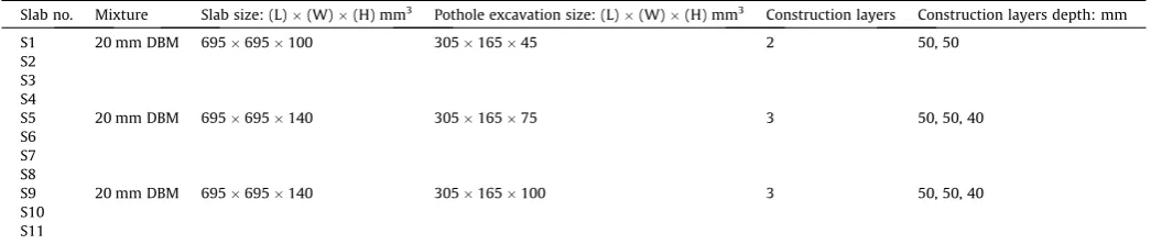
[image:4.595.41.277.436.576.2]The construction parameters of the asphalt slabs are shown in
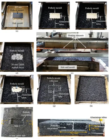
Table 1. The construction process for the 45 mm deep pothole
excavations is shown inFig. 2. For the 75 mm and 100 deep
exca-vation similar construction method was followed but with a larger
number of batches as shown inTable 1and aluminium tubes
(dis-cussed in Section 2.3 below). In total twelve slabs of 695 (±5)
mm695 (±5) mm were built. Each slab was designed with one
pothole excavation of 305 (±2) mm165 (±2) mm located in the
middle of it. The depths of the excavations were 45 (±2) mm, 75 (±2) mm and 100 (±2) mm with respective slab heights 100 (±5) mm and 140 (±5) mm. The chosen pothole depths represent shal-low and deep potholes considering pothole depth range stated by
the following authors. Miller and Bellinger[19]note that potholes
may be deeper than 50 mm and McDaniel et al. [2] state that
patches may range from 38 mm to 152 mm.
Each slab was constructed upside down in batches of 7.6 kg. Twelve, seventeen and eighteen asphalt batches were used to build slabs S1 – S4, S5 – S8 and S9 – S12 respectively. Slabs S1 – S4 were compacted in two lifts, whereas slabs S5 – S12 were compacted in three lifts. Each lift was approximately 50 mm deep and was com-pacted for 7 min using a vibrating plate as described in Standard Code of Practice, New Roads and Street Works Act 1991,
Specifica-tion for the Reinstatement of Openings in Highways (2010)[20].
The lifts were bonded together by dynamically pre-heating each compacted lift with infrared heat to an average surface
tempera-ture 110 (±10)o
C. The pre-heating time was 3 min.
The slabs were demoulded 19 h after their construction. The pothole moulds were removed using infrared heat. To do this, the heater was put above the pothole mould at 230 mm offset. The mould was then heated two or three times for 45 s with 1 min cooling time between the heating times. This was done to allow heat to be conducted from the pothole mould to the excava-tion wall and warm up the asphalt. The mould was then removed by manually pulling it out. There was not any destruction observed in the excavations with the conducted process.
2.3. Method for measuring temperatures within the pothole excavation under dynamic heating
T-type thermocouples (accuracy of 0.5°C)[21] were used to
measure real-time temperatures inside the slabs under dynamic
[image:4.595.32.555.634.745.2]Fig. 1.Composition of slab asphalt mixture.
Table 1
Asphalt slabs construction parameters.
Slab no. Mixture Slab size: (L)(W)(H) mm3
Pothole excavation size: (L)(W)(H) mm3
Construction layers Construction layers depth: mm
S1 20 mm DBM 695695100 30516545 2 50, 50
S2 S3 S4
S5 20 mm DBM 695695140 30516575 3 50, 50, 40
S6 S7 S8
S9 20 mm DBM 695695140 305165100 3 50, 50, 40
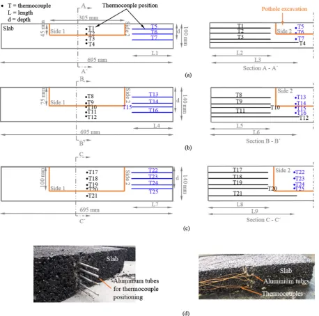
infrared heating. The positions of the thermocouples are described inTables 2 and 3and shown inFig. 3. Hollow aluminium tubes, 4 mm in diameter, were put into the slabs during their construc-tion to accommodate the thermocouples. For a 45 mm deep
pot-hole excavation, 4 slabs (S1-S4,Table 2) were in total built and 7
aluminium tubes of lengths L1, L2 and L3 (Table 3) were put at
varying depths inside each slab. Six tubes were fixed perpendicular
to sides 1 and 2 shown inFig. 2(b), (c) and (f) and one tube was
positioned below and near the bottom face of the excavation (Fig. 2(g)). Although the positioning of the tubes for all slabs was similarly done, the tubes moved during the construction of the slabs. This is expected to have been mainly happening during the
compaction of the slab mixture. For example,Tables 2 and 3show
that thermocouple T1 measured temperature in a depth from the slab surface of 22 (±5) mm and a distance L2 = 243 (±5) mm (Fig. 3). This means that temperature at T1 may have been
[image:5.595.88.515.62.604.2]sured in a depth of 17 mm–27 mm and at a distance of 238 mm– 248 mm. Similarly, but nine aluminium tubes in number, were set inside the slabs for the 75 and 100 mm deep excavations.
T-type thermocouples[21]were also used to measure
temper-atures at eight points into the pothole excavations. A thin steel mesh was used to keep the thermocouples in place during the application of dynamic heat. The mesh helped also to retain the shape of the excavations. Two thermocouples were placed at the bottom corner and mid-area respectively of the excavation, four thermocouples were placed in the middle of the excavation vertical sides, and two thermocouples in the mid-top periphery of the
excavation (Fig. 4andTable 4).
2.4. Description of infrared heating equipment and dynamic heating method for thermal tests
The parameters of the thermal tests are summarised inTable 5.
An experimental infrared heater was used to perform the thermal
tests of this study. The heater is described in Byzyka et al.[22]and
is shown inFig. 5ofSection 2.5. The heater consists of a steel frame
of 1.60 m (L)1.55 m (W). The frame has adjustable height and is
supported by four wheels. The heater contains two heating
ele-ments of 165 mm (L)455 mm (W)102 mm (H). They can
oper-ate at heat powers between 6.6 kW and 7.7 kW and they can be set to be either stationary or moving over the pavement with a stant speed of 0.04 m/s. The heater is operated by its central con-trol unit.
For the thermal tests, the pothole excavations were heated in heating–cooling cycles, referred to as ‘‘dynamic heating”. For the heating part of the cycle, the heater was operating at heat powers 6.6 kW, 6.7 kW, 7.1 kW, 7.5 kW and 7.7 kW. The excavations were heated until the thermocouples closest to the heating element
plate (see T32, T33, T40, T41, T48 and T49 inFig. 4andTable 4)
measured asphalt temperatures between 140°C and 160°C. This
was done to avoid burning the asphalt. Similar asphalt heating
levels are also suggested by previous studies. Uzarowski et al.[6]
suggest heating the repair area to a temperature not greater than
190°C. Nazzal et al. [23] suggest to pre-heat the old pavement
until temperatures reach 135°C to 190°C levels. In addition,
Huang et al.[24] note that heating asphalt between 137°C and
226°C reduces ageing or charring of asphalt binder. Asphalt ageing
happens due to volatilisation, oxidation, and other chemical pro-cesses. Asphalt oxidation should be avoided because it leads to pavement failure due to asphalt binder hardening, change in vis-cosity, asphalt separation, asphalt embrittlement, loss of bitumen
cohesion and bitumen-aggregate adhesion [25]. For the cooling
part of the cycle, the heater was simply turned off and no heating was applied until temperatures of T32, T33, T40, T41, T48 and T49
reached temperatures between 70°C and 80°C. This was done to
allow heat to be conducted within the slab and warm up the asphalt mixture around the pothole excavations.
Further, the tests were conducted with heating applied at 130 mm and 230 mm offsets from the surface of the slab. The heat-ing elements were stationary above the excavations or movheat-ing across the excavations. The moving distance within the heater steel frame was 1 m. This distance could be automatically set to be covered by the heating elements by moving forward and back-wards repetitively within heater steel frame.
2.5. Thermal tests set up
Dynamically heating the pothole excavation is intended to improve common pothole repair practices with or without pre-heating to ultimately increase interface bonding and therefore pot-hole repair durability. The potpot-hole pre-heating method studied in this paper would be expected to follow after the failed asphalt mix-ture of the pavement is removed and the excavation is cleaned from debris and water. Since the pothole excavations studied in the paper were artificially created, these steps were not included in the described processes.
The thermal test set up is shown inFig. 5. Sixty thermal tests
were in total completed (20 tests per pothole excavation depth). Temperatures were measured for a dynamic heating duration of approximately 30 min. The tests were performed 30 days after the construction of the slabs and measurement of thermal conduc-tivity. As the sample size was big, this timeframe was necessary to optimise laboratory resources during sample preparation and pro-duction and carry out additional test (like thermal conductivity) on the whole sample. The ambient temperature during the tests
[image:6.595.32.556.85.240.2]ran-ged between 20°C and 22°C.
Table 2
Position of thermocouples laying inside the slabs.
Slab no. Slab depth: mm Pothole excavation type Thermocouple (T) no. Depth (d): mm
Side 1 Side 2
S1 – S4 100 45 mm deep T1 T5 22 (±5)
T2 T6 42 (±8)
T3 T7 66 (±6)
T4 – 80 (±3)
S5 – S8 140 75 mm deep T8 T13 40 (±5)
T9 T14 65 (±5)
T10 T15 80 (±10)
T11 T16 102 (±6)
T12 – 118 (±4)
S9 – S12 140 100 mm deep T17 T22 25 (±5)
T18 T23 50 (±10)
T19 T24 75 (±10)
T20 T25 90 (±10)
T21 – 120 (±5)
Table 3
Length of thermocouples laying inside the slabs.
Lengths: mm
L1 L2 L3 L4 L5 L6 L7 L8 L9
[image:6.595.32.555.280.318.2]Fig. 3.Demonstration of thermocouple positions and lengths laying inside the slabs for (a) 45 mm; (b) 75 mm; and (c) 100 mm deep pothole excavations. The physical implementation of the previous sketches is shown in (d).
[image:7.595.102.499.582.711.2]3. Asphalt thermal properties
3.1. Thermal conductivity (k)
For this study, thermal conductivity was measured at eleven points per slab prior to commencing the thermal tests. During the measurement of thermal conductivity, the ambient
tempera-ture ranged between 18.5°C and 22.5°C. At the same time, the
temperature of the slabs ranged between 20.5°C and 22°C.
Ther-mal conductivity was measured with the transient line source
(TLS)[26]shown inFig. 6. The temperature of the slabs was also
measured using the TLS.
The TLS includes the TLS controller and a 50 mm needle designed for testing samples that are tough to drill such as rock, concrete or asphalt samples. The TLS has an accuracy of 5% and reproducibility of 2%. The TLS method follows ASTM D5334
(2000)[27]and has been previously used in investigations of
ther-mal conductivity by Chadbourn et al.[15], Blázquez et al.[28]and
Lu et al.[29]. To measure thermal conductivity with the TLS-50
first a 4 mm (D) x 50 mm (H) hole was drilled in the asphalt slab. Then, the excess powder in the hole from drilling was blown out with compressed air. The needle was covered with a thermal paste
called Arctic Alumina[30]before inserting it completely into the
slab. The thermal paste helps to fill any air gaps in the hole and promote good thermal contact between the slab mixture and the needle. Thermal conductivity was calculated by the TLS using Eq.
(1):
k¼ q
4
p
a ð1Þwhere k = thermal conductivity, W/m K; q = heating power, W; a = slope. The slope comes from a plot of temperature rise in the
sample when heated by the TLS versus the logarithm of time[26].
3.2. Specific heat capacity (cP) and thermal diffusivity (a)
Specific heat capacity (cP) and thermal diffusivity (a) were
[image:8.595.31.555.86.145.2]cal-culated using Eq.(2) [14]and Eq.(3) [15]respectively:
Table 4
Characterisation of thermocouples in the pothole excavation
Thermocouple positions
Slab no. Pothole depth Mid-bottom Bottom-corner Mid-side Mid-top
S1 – S4 45 mm T26 T27 T28 T29 T30 T31 T32 T33
S5 – S8 75 mm T34 T35 T36 T37 T38 T39 T40 T41
S9 – S12 100 mm T42 T43 T44 T45 T46 T47 T48 T49
Table 5
Thermal test parameters
Heat Power: kW Heater offset from slab top surface: 130 mm Heater offset from slab top surface: 230 mm
Slab no. Stationary heater Moving heater Stationary heater Moving heater
S1 6.6, 6.7, 7.1, 7.5 and 7.7 U
S2 U
S3 U
S4 U
S5 6.6, 6.7, 7.1, 7.5 and 7.7 U
S6 U
S7 U
S8 U
S9 6.6, 6.7, 7.1, 7.5 and 7.7 U
S10 U
S11 U
[image:8.595.33.549.185.528.2]S12 U
cP¼ 1
mtotal
maggregatecaggregateþmbitumencbitumen
ð2Þ
where m = mass of each material, kg; and c = specific heat capacity of each material, J/kg K.
a¼
q
k cPð3Þ
where
q
= density, kg/m3.4. Air voids content
The air voids content of the compacted asphalt slabs was calcu-lated based on the calculation of the maximum specific gravity and the maximum theoretical specific gravity of asphalt mixture. The
bulk specific gravity (Gmb) was determined through the AASHTO
T166 (2007), method A[31]and the maximum theoretical specific
gravity (Gmm) was calculated with Eq.(4) [32]. In this equation, the
effective specific gravity of aggregate (Gse) was used as 2.65 and
the specific gravity of bitumen (Gb) as 1.01. Thereafter, the
per-centage of air voids in the mixture was calculated with Eq.(5).
Gmm¼ WT Wagg
Gse þ WAC
Gb
ð4Þ
where WT= total eight of asphalt mixture, gr; Wagg = weight of
aggregate, gr; WAC= weight of total asphalt binder, gr.
VTM¼ 1Gmb Gmm
100% ð5Þ
where VTM = voids in total mix, %.
5. Results and discussion
[image:9.595.60.277.67.263.2]5.1. Thermophysical properties
Table 6shows air voids, thermal conductivity, calculated speci-fic heat capacity and thermal diffusivity of the compacted asphalt slabs. The table shows the percentage of air voids from the average of five cores per slab for slabs S1 and S2 and from the average of eight cores per slab for slabs S3 to S12. The cores were extracted throughout the whole sample in order to test overall air voids distribution.
The cores were extracted from the slabs at the end of the ther-mal tests conducted per slab. After the coring, the slabs were not used in any testing. The results show that air voids content ranged from 10% to 13%. The effect of asphalt preheating in air voids has not been investigated in this study due to lack of laboratory equip-ment and no other study for infrared heated patch repair was found to mention it. However, the authors acknowledge that in some areas of the slabs, air voids may have been reduced, while in other areas they may have been increased. This assumption
was done after Norambuena-Contreras and Garcia[33]noted
[image:9.595.44.563.608.755.2]sim-ilar effect of microwave and induction heating in asphalt mixture air voids. The affected areas by the pre-heating would probably be those closer to the heated pothole excavation, near the heater where some cores were also taken or in the areas where heat was conducted due to excavation pre-heating.
Table 6demonstrates that thermal conductivity of the asphalt slabs ranged from 0.98 W/m K to 1.24 W/m K. The results show that thermal conductivity is significantly affected by the high per-centage of air voids in the slabs. This happened because air has
much lower thermal conductivity (0.025 W/m K[34]) compared
to the thermal conductivity of granite aggregate (2.68 W/m K
[34]) and limestone filler (2.92 W/m K[35]) used in this study
and binder (0.39 W/m K [36]). High air voids mean also lower
interlocking between the aggregates of the mixture, less thermal conductance paths into the asphalt mixture and therefore lower thermal conductivity. This effect of air voids in asphalt thermal
conductivity has been also reported by Mirzanamadi et al. [13]
and Hassn et al.[14].
Further, in this study, thermal conductivity was measured with the TLS method. The TLS needle was inserted into holes drilled throughout the slabs and thermal conductivity was calculated by the TLS controller using the heat conduction equation. This means
Fig. 6.TLS-50 instrument for measurement of asphalt thermal conductivity.
Table 6
Thermophysical properties of asphalt mixture
Slab no. Core diameter (mm)
Core height Air voids
content (%) Thermal conductivity (W/m K) Specific heat capacity (J/kg K) Thermal diffusivity (10-7
) (m2 /s)
1 72 1 core of 55 mm & 4 cores of 100 mm per slab
10.04% 1.12 865.44 5.84
2 72 10.51% 1.05 865.44 5.52
3 72 11.99% 0.98 865.44 5.20
4 72 11.18% 1.10 865.44 5.78
5 72 2 cores of 65 mm & 7 cores of 140 mm per slab
13.08% 1.24 865.44 6.72
6 72 11.52% 1.11 865.44 5.86
7 72 12.25% 1.09 865.44 5.80
8 72 10.88% 1.22 865.44 6.39
9 72 2 cores of 40 mm & 7 cores of 140 mm per slab
10.74% 1.00 865.44 5.26
10 72 10.79% 1.16 865.44 6.08
11 72 11.10% 1.18 865.44 6.18
that the measurement of thermal conductivity was affected by the distribution of mineral materials around the drilled hole, the clean-liness of the hole and the thermal contact between the asphalt mixture and the needle.
In addition, specific heat capacity was found equal to 865.44 J/kg K. Specific heat capacity is considerably affected by the temperature and mass of the asphalt mixture. In this study, both parameters remained at similar levels for all slabs. Finally,
thermal diffusivity had been found to range between 5.20107
m2/s and 6.72
107 m2/s. These values were affected by the
range of the thermal conductivity and volumetric heat capacity.
The discussed effect is also noted by Mirzanamadi et al.[13]and
Hassn et al.[14].
5.2. Temperature distribution under dynamic heating
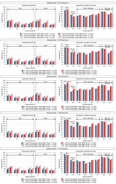
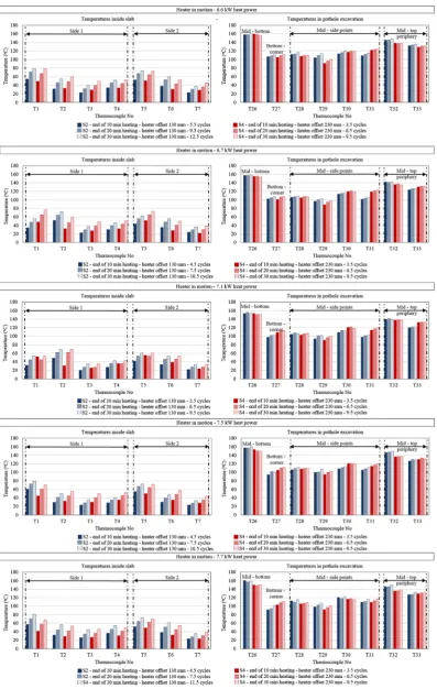
The temperatures captured in the 45 mm, 75 mm and 100 mm deep excavations wall and inside the slabs are presented in
Figs. 7–12. Figs. 7, 9 and 11show temperature profiles for
sta-tionary heater above the excavations. Whereas, Figs. 8, 10 and
12show temperature profiles for moving heater across the
exca-vation. Each figure contains ten graphs and demonstrates temper-atures per thermocouple position at the end of approximately 10 min, 20 min and 30 min dynamic heating. Temperatures are reported for operation of heater with 6.6 kW, 6.7 kW, 7.1 kW, 7.5 kW and 7.7 kW heat powers and for 130 mm and 230 mm heater offsets. The slab number used to perform the thermal tests and the number of heating-cooling cycles for each dynamic heating time are also reported. All thermal tests finish with the heating part of the cycles (or half cycle) and therefore the heating-cooling cycles are reported with numbers such as 3.5,
6.5, 8.5 etc. For example, in Fig. 7, for 10 min dynamic heating
and heater operating at 6.6 kW heat power at 130 mm offset, three and a half cycles were done. For the three whole cycles, the heater was on and off repeatedly. For the half-cycle, the hea-ter was on for some time and then removed from the pothole pre-heating procedure. The hating-cooling cycle procedure was
also described inSection 2.4.
Overall, the results show higher temperatures in the faces of the pothole excavation than inside the slabs. This happened because the temperatures in the excavation increase due to radiation. Whereas, the percentage of the heater radiative energy that reaches the slab and is absorbed by it will increase the temperature of the asphalt mixture inside the slab. The absorptivity of asphalt mixture depends on the colour of the mixture, as light colour
asphalt surfaces have higher reflectance [37], and the surface
roughness[38]. Hassn et al.[14]showed that asphalt pavements
with high percentage of air voids, like the slabs in this study, have higher reflectance than pavements with lower percentage of air voids. This happens because the illumination surfaces and angles
are higher for high air void content mixtures[38]. Once the heater
energy is absorbed by the asphalt, the increase of mixture temper-ature inside the slabs depends on initial slab tempertemper-ature and heat transfer mainly due to conduction which is dependent on the ther-mal properties of the mixture.
5.2.1. Slabs with 45 mm deep pothole excavation
The heating effects of dynamic heating are shown inFigs. 7 and
8. It is observed that temperatures in the pothole excavation and
inside the slab were increased non-uniformly. The temperature increase rate inside the slab was higher for the first 10 min of heat-ing than between 10 min and 30 min of heatheat-ing. This happened because thermal conductivity decreases while mixture tempera-ture increases. The effect of temperatempera-ture in thermal conductivity of asphalt mixture was not measured in this study. However, it
has been previously noted by Chadbourn et al. [15] for
temperatures between 25°C and 75°C and by Pan et al.[35]for
temperatures between20°C and 60°C. Further, Pan et al.[35]
suggest that the decrease of thermal conductivity at higher mix-ture temperamix-tures is mainly affected by the thermal conductivity of aggregates, as they account for more than 90% of the mixture, than the thermal conductivity of the binder.
Overall, temperatures measured in the mid-bottom of the pot-hole excavation (T26) exhibited the highest increase in
tempera-ture and reached 140°C to 160°C. High temperatures but lower
than T26, mainly in the region of 120°C to 140°C, were observed
in the mid-top periphery of the pothole excavation (T32 and T33). There were two reasons that T26 had higher temperatures than T32 and T33. Firstly, temperatures on the heating element plate were higher in the central region of the plate than in the
periph-ery and the ends of the plate (this is shown in Ref.[22]).
Sec-ondly, T32 and T33 were located at the top of the excavation periphery and it seems that the heat loss was higher in those points than at the bottom of the excavation. This also shows that the effect of the external environment was higher for T32 and T33 than T26. In addition, the lowest temperatures were observed in the sides (T28-T31) and the corner (T27) of the pothole excava-tion. This shows that the heater had a larger view of the points located in the horizontal faces of the pothole excavation than the points located in the vertical faces of the excavation. To this
extent, temperatures for T28-T31 and T27 ranged from 80°C to
120°C.
Overall, temperatures in the pothole excavation were higher for 7.7 kW than for 6.6 kW. However, no increasing or decreasing trend was observed for temperatures resulted for heater heat pow-ers in between the 6.6 kW–7.7 kW range. This meaning that tem-peratures in the pothole excavation may either increase or decrease without depending on the heater heat power between the noted above heat power range. Similar reaction was also observed when excavation temperatures were compared (a) between 130 mm and 230 mm heater offsets for stationary and moving heater for each heater operating heat power and (b) between stationary and moving heater for 130 mm and 230 mm heater offsets for each heater operating heat power.
Heat inside the slabs was transferred from top to bottom. Tem-peratures tend to increase during the heating-cooling cycles but had a lowering trend from the top to the bottom of the slabs. The latter is mainly attributed to the slow heat transfer due to low thermal conductivity and volumetric specific heat capacity of the asphalt mixture of this study. Overall, thermocouples T1 and T5 located closer to the top surface of the slabs captured
tempera-tures between 40°C and 80°C. Below T1 and T5, temperatures for
T2-T4, T6 and T7 ranged from 20°C to 70°C. A similar pattern in
temperature increase between temperatures in pothole excavation and inside the slabs was observed for the three different durations of dynamic heating with heater being either stationary or in motion.
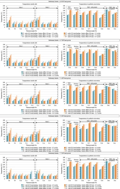
5.2.2. Slabs with 75 mm deep pothole excavation
The temperature profile under dynamic heating is shown in
the 45 mm deep pothole excavation for stationary heater. T39 located in one of the vertical faces of the excavation was the only thermocouple that had lower temperatures than the rest of the
[image:11.595.105.505.62.695.2]excavation. This may have happened because the thermocouple moved or was mistakenly covered by a wire of the steel mesh that was holding the thermocouples in place during the thermal tests.
FromFig. 10, it is also observed that for moving heater thermo-couple T41 had significantly lower temperatures than T40 although both thermocouples were located at the top of the
[image:12.595.96.494.63.690.2]exca-vation. This happened because the heater was moving across the excavation and perpendicular to the long sides of the pothole where T41 was located in the middle of it. The air circulation
due to the moving heater seems to have significantly affected and cooled down the temperatures of T41 compared to T40.
Reflecting the above, between 10 min and 30 min heating for stationary heater at 130 mm offset, temperatures for T34-T38 were
94°C – 130°C; for T39 were 76°C – 91°C; for T40 were 143°C –
150°C; and for T41 were 106°C – 136°C. Whereas, at heater offset
230 mm, temperatures for T34-T38 were 103°C – 164°C; for T39
[image:13.595.103.500.67.689.2]were 89°C – 129°C; for T40 were 135°C - 146°C; and for T41 were
90°C – 134°C (Fig. 9). For moving heater at 130 mm offset
temper-atures for T34-T38 were 84°C – 117°C; for T39 were 51°C – 74°C;
for T40 were 146°C – 158°C; and for T41 were 94°C – 127°C.
Whereas, at heater offset 230 mm, temperatures for T34-T38 were
96°C – 140°C; for T39 were 83°C – 110°C; for T40 were 140°C –
[image:14.595.92.492.64.689.2]156°C; and for T41 were 90°C – 137°C (Fig. 10).
For internal slab temperatures, for both stationary and heater in
motion at 130 mm offset, temperatures were fluctuating from 30°C
to 70°C for T8. This sensor was located closer to the top surface of the
slab. Below T8, temperatures ranged between 25°C and 50°C
[image:15.595.104.503.61.689.2](T9-T11 and T14-T16). Similar temperatures to T8 were captured from thermocouple T12 located below the bottom surface of the pothole
excavation. For 230 mm offset, the temperature profile inside the slab did not change significantly. Specifically, T8 captured
tempera-tures between 50°C and 90°C and temperatures for T9-T11 and
T14-T16 ranged from 25°C to 75°C and 20°C to 55°C respectively.
T12 measured temperatures between 40°C and 75°C. T13 showed
[image:16.595.92.491.62.685.2]temperatures between 50°C and 110°C (Figs. 9 and 10).
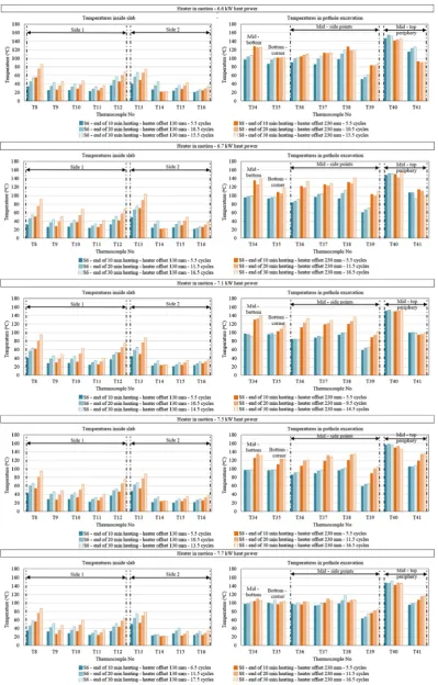
5.2.3. Slabs with 100 mm deep pothole excavation
The heating effects of dynamic heating are shown inFigs. 11
and 12. Higher temperatures were seen between the excavation and inside the slab. Temperatures inside the slab were higher in the upper part of the slab and lower near the bottom of the slab.
[image:17.595.76.531.145.424.2]Both temperature trends were seen for the 45 mm and 75 mm deep excavations. However, temperatures measured in the 100 mm deep excavation were even more uniform than the 45 mm and 75 mm deep excavations. Overall, temperatures for thermocouples T42 to T46 located within the excavation ranged
Fig. 13.Temperature increase percentage per thermocouple for approximately 10 min heating in 45 mm deep pothole excavation.
[image:17.595.78.533.461.740.2]between 80°C and 110°C. The lowest temperatures in the excava-tion were seen for T47. For this sensor, for staexcava-tionary and heater in
motion at 130 mm offset, temperatures were between 50°C and
65°C. For 230 mm offset, temperatures ranged between 65°C
and 85°C. The highest temperatures were observed in the top of
the excavation. These temperatures were captured by T48 and
T49 and ranged between 110°C and 160°C. The effect of cooling
[image:18.595.63.523.145.423.2]at T48 due to heater moving across the excavation was mainly observed at heater operating heat powers between 6.7 kW and 7.7 kW.
Fig. 15.Temperature increase percentage per thermocouple for approximately 10 min heating in 100 mm deep pothole excavation.
[image:18.595.64.515.459.739.2]Inside the slab mixture, the temperature for points closer to the
top surface of the slab ranged from 30°C to 70°C (T17) and from
45°C to 85°C (T22). At lower depths, temperatures were between
20°C and 55°C. These temperatures were measured by T18-T20
and T23-T25 and were affected by the thermal properties of the mixture as already discussed. Finally, temperatures between
30°C and 55°C were captured from thermocouple T21 located
below the bottom surface of the pothole excavation.
5.2.4. Optimum dynamic heating methods for 45 mm, 75 mm and 100 deep pothole excavations
For each temperature sampling point, the effect of heater power, offset and state above the excavations was analysed. This
was discussed in Sections 5.2.1–5.2.3. The optimum heating
method per pothole excavation was found by examining only the temperatures inside the slabs for approximately 10 min of heating. This was done because the results showed that the tem-perature increase rate inside the slab was higher for the first 10 min of heating than between 10 min and 30 min of heating. The optimum methods were chosen after finding the method
that offered the highest increase of temperature per thermocou-ple; was performed with lower number of heating-cooling cycles; and low heat power was used for the heating part of the cycles. The temperatures in the pothole excavation were not considered because the results showed that same tempera-ture levels were achieved with each heating-cooling cycle. How-ever, more heating time was needed to warm up the internal mixture of the slabs.
Initially, five best heating methods were chosen among the
twenty thermal tests conducted per pothole excavation.Figs. 13,
14 and 15 present the concluded five methods. In these figures, the temperature increase per thermocouple location is compared against each method. Then, the optimum pre-heating method for 45 mm, 75 mm and 100 mm deep excavation was concluded and
shown inFig. 16, after eliminating the heating methods that did
not meet the criteria discussed in the previous paragraph. The time frame of heating-cooling cycles for optimum dynamic
heating methods for all excavations are presented inFig. 17. For
45 mm and 100 mm deep pothole excavations optimum heating methods with stationary and heater in motion are suggested.
[image:19.595.55.547.304.740.2]ever, to avoid overheating a larger area around a pothole
excava-tion of 305165 mm2, stationary heater is preferable.
6. Conclusions and future work
This study experimentally investigated the temperature profile in asphalt slabs and various depths of pothole excavations during dynamic infrared heat application. Temperatures were studied for various slab-heater configurations. These were 130 mm and 230 mm heater offsets and operating heat powers from 6.6 kW to 7.7 kW for stationary and moving heater. For each temperature sampling point, the effect of heater power, offset and state above the excavations was analysed. The main conclusions drawn from the research are the following:
Temperatures under dynamic infrared heating in 45 mm,
75 mm and 100 mm deep pothole excavations and their host pavement were non – uniformly distributed.
There was higher concentration of temperatures in the pothole
excavation than inside the host pavement. This happened because temperatures in the excavations increase due to radia-tion. Whereas, the temperature profile inside the host pave-ment depends on the thermal properties of the asphalt mixture.
Temperatures inside the host pavement increased more for the
first 10 min of heating than for heating between 10 min and 30 min.
Dynamically heating a pothole excavation ensures heating up of
its external surfaces and internal asphalt mixture of host pave-ment without burning or overheating the asphalt. For this rea-son and to keep patching time to a minimum, 10 min–12 min dynamic heating time is better.
It is suggested that 45 mm deep pothole excavation is
dynami-cally heated for approximately 10 min with (a) 6.6 kW heat power and stationary heater above the pothole excavation at an offset from the asphalt surface 230 mm and (b) 7.5 kW heat power and heater in motion at an offset 130 mm. Method (b)
preferred for pothole areas bigger than 305165 mm2.
It is suggested that 75 mm deep pothole excavation is
dynami-cally heated for approximately 10 min with 7.1 kW heat power at an offset 230 mm.
It is suggested that 100 mm deep pothole excavation is
dynam-ically heated for approximately 10 min with (a) 6.6 kW heat power and stationary heater at an offset 230 mm and (b) 7.5 kW heat power and heater in motion at an offset 130 mm.
Method (b) preferred for pothole areas bigger than
305165 mm2.
Dynamically heating the pothole excavation is intended to
improve interface pothole repair bonding and therefore repair durability over time. The suggested optimum heating may be implemented in asphalt patch repairs prior to any pothole fill-ing and compaction and after the failed asphalt is removed and the cavity is cleaned from debris and water.
Further investigation is underway to evaluate interfacial
bonding and long-term performance under moving wheel load as a quality improvement tests. In addition, the impact of preheating at different environment condition, host asphalt pavement mixtures and pothole fill materials are also under investigation.
From the research it has also been concluded that future
research must explore the effect of dynamic infrared heating in bitumen loses and disturbance of air voids in host pavement.
The effect of thermal properties, asphalt absorptivity and
sur-face roughness in infrared heated repairs should also be further investigated.
Conflict of interest
None.
Acknowledgement
This work was financially supported by International Chem-Crete Corporation, Texas, USA, EPSRC, Epicuro Ltd and DAC Con-sulting (UK) Ltd., Nynas UK AB and Conexpo (NI) Ltd supported by providing materials. Thermtest company supported in thermal conductivity instrument testing. Laboratory work was supported by Brunel University technical staff Neil Macfadyen and under-graduate student Kamal Ahmad.
References
[1]A. Dawson, Water in road structures: movement, drainage & effects, Springer Science & Business Media, Dordrecht, the Netherlands, 2008.
[2]R.S. McDaniel, J. Olek, A. Behnood, B. Magee, R. Pollock, Pavement Patching Practices (Project 20–05, Topic 44–04), National Cooperative Highway Research Program, Transportation Research Board, Washington, D.C., 2014. [3] J.R. Blaha, Fabrication and Testing of Automated Pothole Patching Machine
(No. SHRP-H-674), Washington, D.C. Strategic Highway Research Program, National Research Council, 1993.
[4] D.A. Anderson, H.R. Thomas, Pothole Repair in Pennsylvania.https://docs.lib. purdue.edu/cgi/viewcontent.cgi?referer=&httpsredir=1&article=3367& context=roadschool&sei-redir=1&referer=http%3A%2F%2Fcn.bing.com% 2Fsearch%3Fq%3DPothole%2BRepair%2Bin%2BPennsylvania&go%3D%25E6% 258F%2590%25E4%25BA%25A4&qs%3Dn&form%3DQBLH&pq%3Dupper% 2Bgreat%2B, 1984 (accessed 20 June 2018).
[5] T.R. Clyne, E.N. Johnson, B.J. Worel, Use of taconite aggregates in pavement applications (No. MN/RC-2010-24), Minnesota Department of Transportation, Saint Paul, MN, USA, 2010.
[6] L. Uzarowski, V. Henderson, M. Henderson, B. Kiesswetter, Innovative Infrared Crack Repair Method, in: Proceedings of Congress et Exhibition de l’Association des Transports du Canada, 2011 Les Succes en Transports: Une Tremplin vers l’Avenir, Edmonton, Canada, 2011.
[7]T.J. Freeman, J.A. Epps, HeatWurx Patching at Two Locations in San Antonio (No. FHWA/TX-12/5-9043-01-1), Texas Transportation Institute, FHWA, Texas Department of Transportation, Austin, 2012.
[8] C.W. Leininger, Optimization of the infrared asphalt repair process, Master’s Thesis, University of Maryland. https://search.proquest.com/openview/ 5d63e8ff20aa8561ec9f4e81b6fc75fe/1?pq-origsite=gscholar&cbl=18750& diss=y, 2015 (accessed 20 June 2018).
[9] H. Obaidi, B. Gomez-Meijide, A. Garcia, A fast pothole repair method using asphalt tiles and induction heating, Constr. Build. Mater. 131 (2017) 592–599,
https://doi.org/10.1016/j.conbuildmat.2016.11.0999.
[10]M.F. Modest, Radiative heat transfer, fourth ed., Academic press, Oxford, Amsterdam, 2013.
[11]T.L. Bergman, F.P. Incropera, D.P. DeWitt, A.S. Lavine, Fundamentals of heat and mass transfer, seventh ed., John Wiley & Sons, Hoboken, New Jersey, 2011. [12]O.B. Andersland, B. Ladanyi, Frozen ground engineering, second ed., John Wiley
& Sons Inc, Hoboken, New Jersey, 2004.
[13] R. Mirzanamadi, P. Johansson, S.A. Grammatikos, Thermal properties of asphalt concrete: a numerical and experimental study, Constr. Build. Mater. 158 (2018) 774–785,https://doi.org/10.1016/j.conbuildmat.2017.10.068. [14] A. Hassn, M. Aboufoul, Y. Wu, A. Dawson, A. Garcia, Effect of air voids content
on thermal properties of asphalt mixtures, Constr. Build. Mater. 115 (2016) 327–335,https://doi.org/10.1016/j.conbuildmat.2016.03.106.
[15] B.A. Chadbourn, J.A. Luoma, D.E. Newcomb, V.R. Voller, Consideration of hot mix asphalt thermal properties during compaction, in: Anonymous Quality management of hot mix asphalt, ASTM International, 1996.
[16] BS EN 13108 Part 1, Bituminous mixtures – Material specifications, British Standard Institute (BSI), 2016.
[17] Manual of contract documents for Highway works, Volume 1, Specification for highway works, Series 900 Road pavements - Bituminous bound materials, 2008.
[18] BS EN 12697 Part 35, Bituminous mixtures - Test methods, Laboratory mixing, British Standard Institute (BSI), 2016.
[19]J.S. Miller, W.Y. Bellinger, Distress identification manual for the long-term pavement performance program (No. FHWA-HRT-13-092), United States, Federal Highway Administration, Office of Infrastructure Research and Development (2014).
[20] Department of Transportation, Standard Code of Practice, New Roads and Street Works Act 1991, Specification for the Reinstatement of Openings in Highways, third ed. (England), Department of Transportation, 2010. [21] Omega, Hermetically Sealed Thermocouple.http://www.omega.co.uk/pptst/
[22] J. Byzyka, D.A. Chamberlain, M. Rahman, Development of advanced temperature distribution model in hot-mix asphalt patch repair, in: Proceedings of the Institution of Civil Engineers – Transport. (2017) 1–11.
https://doi.org/10.1680/jtran.17.00022.
[23] M.D. Nazzal, S. Kim, A.R. Abbas, Evaluation of winter pothole patching methods, Columbus: FHWA, Ohio Department of Transportation, Publication FHWA/OH-2014/2, 2014.
[24] K. Huang, T. Xu, G. Li, R. Jiang, Heating effects of asphalt pavement during hot in-place recycling using DEM, Constr. Build. Mater. 115 (2016) 62–69,https:// doi.org/10.1016/j.conbuildmat.2016.04.033.
[25]T. Mill, D.S. Tse, B. Loo, C.C.D. Yao, E. Canavesi, Oxidation pathways for asphalt, Prepr. ACS Div. Fuel Chem. (1992) 37–43.
[26] Thermtest, Thermtest TLS-100, Portable transient line source, thermal conductivity meter for soil thermal conductivity testing as well as rock, concrete, and polymers.https://thermtest.com/tls-100, 2018 (accessed: 5 July 2018). [27] ASTM D5334, Standard Test Method for Determination of Thermal
Conductivity of Soil and Soft Rock by Thermal Needle Probe Procedure, American Society for Testing and Materials (ASTM) (2000).
[28] C.S. Blázquez, A.F. Martín, P.C. García, D. González-Aguilera, Thermal conductivity characterization of three geological formations by the implementation of geophysical methods, Geothermics 72 (2018) 101–111,
https://doi.org/10.1016/j.geothermics.2017.11.003.
[29] Y. Lu, W. Yu, D. Hu, W. Liu, Experimental study on the thermal conductivity of aeolian sand from the Tibetan Plateau, Cold Reg. Sci. Technol. 146 (2018) 1–8,
https://doi.org/10.1016/j.coldregions.2017.11.006.
[30] Overlockers, Alumina thermal paste (14g).https://www.overclockers.co.uk/ arctic-silver-alumina-thermal-paste-14g-th-006-ac.html, 2018 (accessed 5 July 2018).
[31] AASHTO, T166, Bulk specific gravity of compacted asphalt mixtures using saturated surface - dry specimens, American Association of State Highway and Transportation Officials (AASHTO) (2007).
[32]F.L. Roberts, P.S. Kandhal, E.R. Brown, D. Lee, T.W. Kennedy, Hot Mix Asphalt Materials, Mixture Design and Construction, second ed., National Asphalt Pavement Association Education Foundation, Lanham, Maryland, 1991. [33] J. Norambuena-Contreras, A. Garcia, Self-healing of asphalt mixture by
microwave and induction heating, Mater. Design 106 (2016) 404–414,
https://doi.org/10.1016/j.matdes.2016.05.095.
[34] L. Eppelbaum, I. Kutasov, A. Pilchin, Methods of Thermal Field Measurements. In: Applied Geothermics, Lecture Notes in Earth System Sciences, Springer, Berlin, Heidelberg, 2014, pp. 151–159. https://doi.org/10.1007/978-3-642-34023-9_3.
[35] P. Pan, S. Wu, X. Hu, P. Wang, Q. Liu, Effect of freezing-thawing and ageing on thermal characteristics and mechanical properties of conductive asphalt concrete, Constr. Build. Mater. 140 (2017) 239–247,https://doi.org/10.1016/ j.conbuildmat.2017.02.135.
[36] P. Pan, S. Wu, Y. Xiao, P. Wang, X. Liu, Influence of graphite on the thermal characteristics and anti-ageing properties of asphalt binder, Constr. Build. Mater. 68 (2014) 220–226, https://doi.org/10.1016/ j.conbuildmat.2014.06.069.
[37] G. Kyriakodis, M. Santamouris, Using reflective pavements to mitigate urban heat island in warm climates-results from a large scale urban mitigation project, Urban Clim. 24 (2018) 326–339, https://doi.org/10.1016/j. uclim.2017.02.002.