p e r i s t al ti c p u m p i n g of c o u pl e
s t r e s s b i ofl ui d s t h r o u g h a
c o m pl e x w a vy m i c r o-c h a n n e l
T ri p a t h i, D, Jo r ar, R, B e g , OA a n d K a dir, A
h t t p :// dx. d oi.o r g / 1 0 . 1 0 1 6 /j. m olli q. 2 0 1 7 . 0 4 . 0 3 7
T i t l e El e c t r o-m a g n e t o-h y d r o d y n a m i c p e r i s t al ti c p u m p i n g of c o u p l e s t r e s s b iofl ui d s t h r o u g h a c o m p l e x w a vy m i c r o-c h a n n el
A u t h o r s T ri p a t h i, D, Jo r ar, R, B e g , OA a n d Ka dir, A
Typ e Ar ticl e
U RL T hi s v e r si o n is a v ail a bl e a t :
h t t p :// u sir. s alfo r d . a c . u k /i d/ e p ri n t/ 4 2 1 5 1 / P u b l i s h e d D a t e 2 0 1 7
U S IR is a d i gi t al c oll e c ti o n of t h e r e s e a r c h o u t p u t of t h e U n iv e r si ty of S alfo r d . W h e r e c o p y ri g h t p e r m i t s , f ull t e x t m a t e r i al h el d i n t h e r e p o si t o r y is m a d e f r e ely a v ail a bl e o nli n e a n d c a n b e r e a d , d o w nl o a d e d a n d c o pi e d fo r n o
n-c o m m e r n-ci al p r iv a t e s t u d y o r r e s e a r n-c h p u r p o s e s . Pl e a s e n-c h e n-c k t h e m a n u s n-c ri p t fo r a n y f u r t h e r c o p y ri g h t r e s t r i c ti o n s .
JOURNAL OF MOLECULAR LQIUIDS
ISSN: 0167-7322
Impact Factor: 2.740
PUBLISHER: ELSEVIER
Accepted April 11th 2017
ELECTRO-MAGNETO-HYDRODYNAMIC PERISTALTIC PUMPING OF COUPLE
STRESS BIOFLUIDS THROUGH A COMPLEX WAVY MICRO-CHANNEL
*1
Dharmendra Tripathi, 1Ravinder Jhorar,2O. Anwar Bég and A. Kadir3
1
Department of Mechanical Engineering, Manipal University Jaipur, Rajasthan-303007, India. 2
Fluid Mechanics, Bio-propulsion and Nanosystems, Mechanical and Aeronautical Engineering, Salford University, Newton Building, The Crescent, Salford, M54WT, England, UK. 3
Materials, Corrosion and Structures, Petroleum and Gas Engineering Division, Salford University, Newton Building, The Crescent, Salford, M54WT, England, UK.
*Corresponding author- email: [email protected] ABSTRACT
Biomimetic propulsion mechanisms are increasingly being explored in engineering sciences. Peristalsis is one of the most efficient of these mechanisms and offers considerable promise in microscale fluidics. Electrokinetic peristalsis has recently also stimulated significant attention. Electrical and magnetic fields also offer an excellent mode for regulating flows. Motivated by novel applications in electro-conductive microchannel transport systems, the current article investigates analytically the electromagnetic pumping of non-Newtonian aqueous electrolytes via peristaltic waves in a two-dimensional microchannel with different peristaltic waves propagating at the upper and lower channel wall (complex wavy scenario). The Stokes couple stress model is deployed to capture micro-structural characteristics of real working fluids. The unsteady two-dimensional conservation equations for mass and momentum conservation, electro-kinetic and magnetic body forces, are formulated in two dimensional Cartesian co-ordinates. The transport equations are transformed from the wave frame to the laboratory frame and the electrical field terms rendered into electrical potential terms via the Poisson-Boltzmann equation, Debye length approximation and ionic Nernst Planck equation. The dimensionless emerging linearized electro-magnetic boundary value problem is solved using integral methods. The influence of Helmholtz-Smoluchowski velocity (characteristic electro-osmotic velocity), couple stress length parameter (measure of the polarity of the fluid), Hartmann magnetic number, and electro-osmotic parameter on axial velocity, volumetric flow rate, time-averaged flow rate and streamline distribution are visualized and interpreted at length.
Keywords: Peristalsis; Electro-Osmosis; Magnetohydrodynamics; Trapping; Biomimetic
1. INTRODUCTION
have been communicated by Natarajan and Mokhtarzadeh-Dehghan [18], Fauci [19], Jaffrin [20] (considering inertial curvature effects), Berg et al. [21] (who considered a discrete, two-stage peristaltic microfluidics pump). Afifi and Gad [22] derived perturbation solutions for peristaltic flow interacting with periodic blood flow for a viscous incompressible fluid flow in a porous medium. Radhakrishnamacharya and Srinivasulu [23] studied the influence of wall elasticity (tension, damping and mass characterizing parameters) on peristaltic Newtonian flow and heat transfer in a two dimensional uniform channel. Chu [24] considered the hydrodynamic stability of peristaltic waves in a deformable conduit using a preconditioned complex-matrix solver.
Electrokinetics [25] has developed into a major branch of modern fluid dynamics. It arises in many medical applications including blood flows, microfluidics, chromatography, plasma separation and colloidal suspension fabrication and manipulation. Electrokinetics deals with the interaction between heterogeneous fluids contacting charged particles and static or alternating electric fields. It is important in simulating transport processes in ionic solutions in the vicinity of electrically-charged interfaces. Many sophisticated phenomena arise in electro-kinetics including electro-osmosis, zeta potential, dielectrics, diffusiophoresis, streaming potential/current, capillary osmosis, sedimentation potential etc. The proliferation of micro- and nanoscaled devices in bioengineering systems has witnessed significant developments in electro-kinetics. Kang et al. [26] reported in fabrication of electrokinetic micropumps. Yang et al. [27] considered AC electro-osmotic (ACEO) pumping on a symmetric gold electrode array. Many other studies have been communicated including Paul
et al. [28], Sayar and Farouk [29] (who simulated coupled multifield flow in a piezoelectrically actuated valveless micropump device for liquid transport). Tripathi et al. [30] used a linearized analytical model to elucidate the effects of electro-osmotic velocity on peristaltic pumping of blood in capillaries.
reactive micropolar fluids [38] and viscoelastic two-phase (dusty) magnetic fluids [39]. Ramos [40] has lucidly reviewed the advantages and drawbacks of electro/magnetic micro-pumps including peristaltic designs, emphasizing the deterioration, corrosion and electrochemical bubble issues which can cause flow obstructions and lower pumping efficiency in purely magnetohydrodynamic pumps. Motivated by exploring the combined influence of axial electric field and transverse magnetic field in micropumps, Tripathi et al.
[41] presented a theoretical study of combined electrokinetic magnetohydrodynamic peristaltic transport with electrical double layer effects. They observed that higher magnetic field (Hartmann number) decreases flow rate, local wall shear stress, axial velocity whereas it elevates pressure difference. They also noted that with higher electro-osmotic parameter (i.e. smaller Debye length), there is an enhancement in flow rates.
Thusfar however to the authors’ knowledge there has been no study reported investigating the
combined effects of magnetic field and electrical field on peristaltic flow of couple stress
fluids. This is the focus of the present investigation. It extends the existing work in the field which has previously been confined to electrofluid thermal viscoelastic dielectric peristalsis [49], electrokinetic Jefferys (viscoelastic) peristaltic pumping [50] and electro-osmotic power-law peristaltic pumping [51]. The present work is relevant to simulation of real working fluids in electromagnetic biomimetic microscale pumps utilizing the peristaltic propulsion mechanism [52]. Such pumps avoid contamination problems, minimize maintenance and also achieve greater longevity and efficiency which may have immense potential in bio-inspired portable intravenous drip systems for medical treatments in the 21st century.
2. MATHEMATICAL MODEL
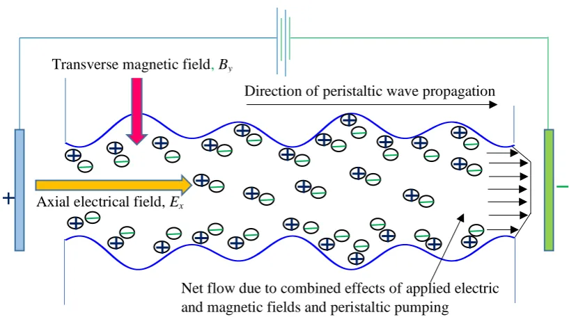
The geometric model for the electro-kinetic transport through a finite length (L) micro-porous-channel under two different peristaltic waves propagating along the upper and lower walls, depicted in Fig.1, is modelled as Cho and Chen[53]:
1 2
2 4
( , ) sin ( ) sin ( )
h x t a x ct x ct
, (1)
where a,1,
2,,x,c,t are the half-width of the channel, amplitude of the differentperistaltic waves along the microchannel walls, wavelength, axial coordinate, wave velocity, and time and a,
1, and
2 satisfy the conditiona
1 2. We analyse the electro-magneto-hydrodynamics of oscillating flow of couple stress fluids through a complex wavy channel under peristaltic waves. All classical electromagnetic phenomena are described by the Maxwell field equations. In fig. 1 we further note that the peristaltic wave propagates from the left reservoir (Anode, +ve ion) to the right reservoir (Cathode, -ve ion) with a wave velocity c. In the presence of static axial electric field and static transverse magnetic field, the mass and momentum conservation equations for incompressible couple stress fluid are modified with addition of Lorentz force per unit volume, and written as:
0, ddiv q
dt (2)
1 1
,
2 2
s
e
dq
f curl C div curl div M E J B
dt
where is the density of the fluid, s is the symmetric part of the force stress diad, M is the couple stress diad and f , C are the body force per unit mass and body couple per unit mass respectively, q is the velocity vector. Here e z n e z n e , denotes the charge number density of the aqueous solution present, where e is the charge, n+ and n- are the
number densities of cations and anions respectively, z and z are cation and anion valencies, and E,J and B represent the electric field, current density and magnetic flux density (magnetic field strength). The constitutive equations concerning the force stress ti j
[image:7.595.88.497.262.490.2]and the rate of deformation tensor di jare given by:
Figure 1: Schematic of the peristaltic transport of an aqueous electrolyte solution with couple stress through a parallel micro-channels induced by axial electric field and transverse magnetic field.
,
1
( ) 2 ( , 4 )
2
ij ij ij ij ijk k k rr k
t p div q d m w C . (4) The couple stress tensor mij that arises in the theory has following linear constitutive relation, as described by Stokes [44]:
, ,
1
4 4
3
ij ij j i i j
m m w w , (5)
where 1
2
w curl q is the spin vector, wi j, is the spin tensor, m is the trace of couple stress
tensor mij, p is the fluid pressure and Ckis the body couple vector. A comma in the
suffixes denotes covariant differentiation and wk rr, stands for wk,11 + wk,22 + wk,33. The
Direction of peristaltic wave propagation
Net flow due to combined effects of applied electric and magnetic fields and peristaltic pumping
Transverse magnetic field, By
quantities and are the viscosity coefficients and , ′ are the couple stress viscosity coefficients. These material constants are constrained by the inequalities,
0; 3 2 0; 0; '
. (6) If the fluid is incompressible, in the absence of body forces and body couples, and axial external electric field (Ex) and transverse magnetic field (By) effects (i.e. mutually
orthogonal) are taken into consideration, the reduced governing equations for mass and momentum conservation may be expressed as:
0,
u v x y
(7)
2 4 2
x e x
u u u p
u v u u B u E
t x y x
, (8)
2 4
v v v p
u v v v
t x y y
. (9)
The penultimate term on the right hand side of eqn. (8) denotes the Lorentzian magnetic body force and the last term represents the electrokinetic body force. In this model, we consider the case where the peristaltic transport of an aqueous ionic solution of couple stress fluids is altered by means of an externally applied electric field and transverse magnetic field along the length of channel. The positive ions n and negative ion n are both assumed to have bulk concentration (number density) n0, and a valency of z and z respectively. For
simplicity, we consider the electrolyte to be a z z: symmetric electrolyte, i.e. z z z. The charge number density is related to the electrical potential in the transverse direction through the Poisson equation:
2 e
, (10)
where is the permittivity of the electromagnetic couple stress fluid. Further, in order to determine the potential distribution, we need to describe the charge number density. For this, the ionic number distributions of the individual species are given by the Nernst-Planck equation for each species as:
2 2
2 2
B
n n n n n Dze
u v D n n
t x y x y k T x x y y
where we have assumed equal ionic diffusion coefficients for both the species, and that the mobility of the species is given by the Einstein formula where D represents the diffusivity of the chemical species, T is the average temperature of the electrolytic solution and kB is Boltzmann constant. Proceeding with the analysis, we normalize the Poisson and Nernst-Planck equation with the following non-dimensional parameters:
, , , , ,
x y tc u v
x y t u v
a c kc
0 , B ze n n
k T n
. We further note that the nonlinear terms
in the Nernst Planck equations are
2
O Pe k , where PeRe Sc represents the ionic Peclet number, Re is Reynolds number and Sc D denotes the Schmidt number. Therefore, the nonlinear terms may be dropped in the limit that Re, Pe, k <<1. In this limit, Poisson’s equation is obtained as:
2 2 2 , 2 n n y (12)
where 2 0
B d n a aez K T
, is known as the electro-osmotic parameter and d 1
is
Debye length or characteristic thickness of electrical double layer (EDL). The ionic distribution may be determined by means of the simplified Nernst Planck equations:
2
2
0 n n
y y y
, (13)
subjected to n 1 at 0 and n y 0 where y 0 (bulk conditions). These yield the much celebrated Boltzmann distribution for the ions:
ne . (14) Combining equation (12) and (14), we obtain the Poisson-Boltzmann paradigm for the potential determining the electrical potential distribution
2 2 2 sinh
y
. (15)
since for a wide range of pH values, the magnitude of zeta potential is less than 25 mV. Therefore, equation (15) may be contracted to:
2 2 2
y
, (16)
which may be solved subjected to
0 0 y y
and y 1, the potential functionis obtained
as: cosh( )
cosh( ) y h
, (17)
To simplify the governing equations, we invoke a number of non-dimensional parameters, specifically non-dimensional pressure
2 , pa p c
and wavelength-based Reynolds number
c Re
. The nonlinear terms in the momentum equation are found to be
2
O Re k ,
where k a
denotes the ratio of the transverse length scale to the axial length scale. Employing lubrication theory approximations, the governing conservation equations are reduced to:
0 u v x y
, (18)
2 4
2 2 2
2 4 e .
p u u
l Ha u u
x y y
(19)
The associated velocity boundary conditions are:
0
y h
u ,
0 0 y u y , 2 2 0 y h u y 3 3 0 0 y u y
, (20)
where, x e E u c
is the Helmholtz-Smoluchowski velocity or characteristic
electro-osmotic velocity, l 1 , a
is the couple stress length parameter, which is a characteristic
non-polar fluids, Ha aBx
, Hartmann number, which measures the strength of magnetic
body force (Lorentzian force) relative to the viscous force. The reduced fourth order momentum equation (19) allows a parametric study of the couple stress, magnetic body force and electro-osmotic effects via the variation in the l, Ha and parameters.
3. ANALYTICAL SOLUTIONS
Solving Eqn. (19) with boundary conditions (20), the axial velocity is obtained as:
2 2 2 2 2 2 2 2
2 2 2 2 2 2 2 2
1 1 4 1 1 4 1 1 4 1 1 4
2 2 2 2
1 2 3 4
2 2 2 2 4 4 2 2 2
2 2 2 2 2 2 2 2 2
4 ( ) cosh( ) sech( )
,
1 1 4 2 1 1 4 2
y Ha l y Ha l y Ha l y Ha l
l l l l l l l l
e
u C e C e C e C e
p
Ha l l l Ha l u y h
x
Ha Ha l l Ha l l
(21) where,
2 2 2 2 2 21 1 4
2 2 2 2 2 2 2 2 2 2 2 2 2
2
1
2 2 1 4
2 2 2 2 2 2 2 2 2 2 2
2 1 1 4 ( 1 ) 1 1 4 2
,
1 1 4 1 1 4 2 1 1 4 2
h Ha l
l e Ha l h l p
e l Ha l l Ha u Ha Ha l l
x C
e Ha Ha l Ha l l Ha l l
2 2 2 2 2 21 1 4
2 2 2 2 2 2 2 2 2 2 2 2 2
2
2
2 2 1 4
2 2 2 2 2 2 2 2 2 2 2
2 1 1 4 1 1 1 4 2
,
1 1 4 1 1 4 2 1 1 4 2
h Ha l
l e Ha l h l p
e l Ha l l Ha u Ha Ha l l
x C
e Ha Ha l Ha l l Ha l l
2 2 2 2 2 21 1 4
2 2 2 2 2 2 2 2 2 2 2 2 2
2
3
1 1 4 2
2 2 2 2 2 2 2 2 2 2 2
2 1 1 4 1 1 1 4 2
,
1 1 4 1 1 4 2 1 1 4 2
h Ha l
l e Ha l h l p
e l Ha l l Ha u Ha Ha l l
x C
e Ha Ha l Ha l l Ha l l
2 2 2 2 2 21 1 4 2
2 2 2 2 2 2 2 2 2 2 2 2
4
1 1 4 2
2 2 2 2 2 2 2 2 2 2 2 2
2
1 4 1 1 4 2 1 1 4 2
1
1 1 4 1 1 1 4 2 .
h Ha l
l Ha l h l e e
C Ha l Ha l Ha l l Ha l l
e p
Ha l l Ha u Ha Ha l l
x (22) The volumetric flow rate is given by integrating axial velocity across the microchannel width:
0 h
Q
udy. (23)Using Eqn. (12) in Eqn. (13), we get:
2 2 2 2
2 2
2 2 2 2
2 2
1 1 4 1 1 4
2
2 2
1 2
2 2 2 2 4 2 2
1 1 4 1 1 4
2
2 2
3 4
2 2
tanh( ) 2
1 1
1 1 4
2
1 1
1 1 4
Ha l Ha l
h h
l l
e
Ha l Ha l
h h
l l
u h
h p l
Q C e C e
Ha x Ha l Ha l
l
C e C e
Ha l . (24) The transformations between a wave frame (xw,yw)moving with velocity cand the fixed
frame (x y, ) are given by :
, , ,
w w w w
xx ct yy uu c v v , (25) where (u vw, w)and ( , )u v are the velocity components in the wave (laboratory) and fixed
frame respectively.
The volumetric flow rate in the wave frame is given by
0 0
( 1)
h h
w w w w
q
u d y
u dy , (26)which, on integration, yields:
w
Averaging the volumetric flow rate along one time period, we obtain:
1 1
0 0
( w )
Q
Qdt
q h dt, (28)which, on integration, yields 1 1
w
Qq Q h. (29) Rearranging the terms of Eq.(24) and solving for pressuregradient yields:
2 2 2 2
2 2
2 2 2 2
2 2
2 2 2 4
1 1 4 1 1 4
2 2
2 2
1 2
2 2
1 1 4 1 1 4
2 2 2 3 4 2 2 tanh( ) 1 2 1 1
1 1 4 2
1 1
1 1 4
e w
h Ha l h Ha l
l l
h Ha l h Ha l
l l
u k hk p
Q h
x Ha k l k
l Ha
C e C e
h Ha l
l
C e C e
Ha l . (30)
Pressure rise along one wavelength is defined as:
1 0 w w p p dx x
. (31)Using Eqn. (21), the stream function (obeying the Cauchy-Riemann equations, w
w u y and w w v x
) takes the form:
2 2 2 2
2 2
2 2 2 2
2 2
2 2 2 2 4
1 1 4 1 1 4
2
2 2
1 2
2 2
1 1 4 1 1 4
2 2 2 3 4 2 2 tanh( ) 2 1 1
1 1 4
2
1 1 .
1 1 4
e w
h Ha l h Ha l
l l
h Ha l h Ha l
l l
u h
h p
Ha x Ha l
l
C e C e
Ha l
l
C e C e
4. NUMERICAL RESULTS AND DISCUSSION
In this section, we visualize numerical results, evaluated via Mathematica symbolic software, to explore the influence of the key electro-magnetic and hydrodynamic parameters on the flow variables in Figs. 2-5. We consider the dual amplitude peristaltic wave scenario i.e. with two different wave amplitudes (1, 2) at the upper and lower walls of the micro-channel.
1 1 2 3
0.4 0.2 0.2 0.4 0.6 0.8
1 1 2 3
0.5 0.5 1.0
1 1 2 3
0.4 0.2 0.2 0.4 0.6 0.8
(a)
(b)
(c)
Fig.2. Velocity profile (axial velocity vs. transverse coordinate) with
10.2,
2 0.3,and(a) ue 1,l 1,Ha0.1 (b) 0.5,l1,Ha0.1 (c) 0.5,ue 1,Ha0.1 (d)
0.5,ue 1,l 1.1 1 2 3
0.4 0.2 0.2 0.4 0.6 0.8
0.5 1.0 1.5 2.0
0.2 0.1 0.1
0.5 1.0 1.5 2.0
0.3 0.2 0.1 0.1 0.2
(d)
(a)
Fig.3. Volumetric flow rate vs. axial coordinate with
10.2,
2 0.3,p/ x 1,and (a)1, 1, 0.1
e
u l Ha (b) 0.5,l1,Ha0.1(c)
0.5,ue 1,Ha0.1 (d)
0.5,ue 1,l 1.0.5 1.0 1.5 2.0
0.2 0.1 0.1 0.2
0.5 1.0 1.5 2.0
0.2 0.1 0.1
0.2 0.4 0.6 0.8 1.0
0.05 0.05 0.10
(c)
(d)
(a)
Fig.4. Time averaged volumetric flow rate vs. pressure rise across one wavelength with
1 0.2, 2 0.3,
and (a) ue 1,l 1,Ha0.1 (b) 0.5,l1,Ha0.1 (c)0.5,ue 1,Ha 0.1
(d) 0.5,ue 1,l 1.0.2 0.4 0.6 0.8 1.0
0.05 0.05 0.10 0.15
0.2 0.4 0.6 0.8 1.0
0.4 0.3 0.2 0.1 0.1 0.2
0.2 0.4 0.6 0.8 1.0
0.05 0.05 0.10
(b)
(c)
(a)
(c)
(e)
(g)
Fig.5. Stream lines in wave form at 10.2,20.3,Q0.9 for (a) 2,ue 5,l0.1,Ha1 (b) 5,ue5,l0.1,Ha1 (c) 9,ue5,l0.1,Ha1 (d) 5,ue7,l0.1,Ha1
(e) 5,ue9,l0.1,Ha1 (f) 5,ue5,l0.25,Ha1 (g) 5,ue5,l1,Ha1
(h) 5,ue5,l0.1,Ha0.1(i) 5,ue 5,l0.1,Ha0.3
Fig.2a-d illustrate the influence of respectively a) electro-osmotic parameter (
0
2
B d
n a
aez
K T
), b) Helmholtz-Smoluchowski velocity i.e. characteristic
electro-osmotic velocity ( x e
E u
c
), c) couple stress length parameter (l 1 , a
) and d)
Hartmann magnetic parameter (Ha aBx
) on axial velocity (u). There is a progressive
reduction in axial flow with increasing electro-osmotic parameter,, with greater transverse coordinate. Decreasing Debye length therefore results in a damping in the axial flow. The deceleration is induced by the electrokinetic body force in eqn. (19) i.e. 2ue. This damping is generally sustained quite strongly except for higher values of transverse coordinate where the upper microchannel wall is approached and the reverse trend is observed here i.e.
acceleration in the axial flow. Fig 2b shows that with greater negative Helmholtz-Smoluchowski velocity, ue, the axial flow is accelerated whereas with greater positive values
the flow is decelerated. Generally the case of vanishing electrical field (ue, =0) falls between
the other profiles. With increasing couple stress length parameter (l) in fig. 2b there is a marked acceleration in the axial flow. Stronger couple stresses in the aqueous solution therefore encourage axial momentum development across the channel span. Fig 2d reveals that with increasing magnetic parameter, Ha, there is acceleration in the axial flow. This is maintained across the channel span. Magnetic field therefore induces the opposite response to electrical field in the regime. In all figs 2a-d the maximum axial flow velocity is computed at the lower microchannel wall and there is decay in velocity across the channel span to a minimum in the vicinity of the upper channel wall.
Figs. 3a-d visualize the influence of respectively a) electro-osmotic parameter (i.e.
0
2
B d
n a
aez
K T
), b) Helmholtz-Smoluchowski velocity i.e. characteristic
electro-osmotic velocity ( x e
E u
c
), c) couple stress length parameter (l 1 , a
) and
d)Hartmann magnetic parameter (Ha aBx
) on volumetric flow rate (Q). These graphs
are plotted against axial coordinate. The irregularity in the profiles is associated with the complex dual amplitude peristaltic waves imposed at the two microchannel walls. With increasing electro-osmotic parameter,, the flow rate is significantly enhanced (fig 3a). With increasing negative Helmholtz-Smoluchowski velocity, ue, flow rates are generally enhanced
strongly. The converse behaviour is computed with positive Helmholtz-Smoluchowski velocity. In the former case the electrical field is directed along the positive x-axis and in the latter case it is in the reverse axial direction. Therefore with axial electrical field aligned with the direction of propagation of peristaltic waves, the flow is accelerated. It is inhibited when the electrical field is in the opposite direction to wave propagation. This confirms that that aligned axial electrical field and electro-kinetic effects are beneficial to the peristaltic pumping process, as elaborated by Goswami et al. [54] although they considered only power-law rheological fluids. With increasing couple stress effect (fig. 3c) there is also a substantial enhancement in flow rate which is associated with the acceleration in the axial flow owing to greater couple stresses. The couple stress parameter, l 1 ,
a
the Newtonian dynamic viscosity and directly proportional to the polar viscosity. As this parameter is increased there is progressively less viscous resistance to the propulsion of aqueous electrolyte in the microchannel which manifests in axial acceleration. Fig. 3d shows that with greater Hartmann number, there is a consistently strong enhancement in volumetric flow rate, confirming the axial flow acceleration observed in the flow velocity computations in fig. 2d. This is achieved despite the fact that the viscous force still exceeds magnetic Lorentzian body force for all the cases in fig. 3d (Ha <1). Transverse magnetic field is therefore assistive to peristaltic pumping.
Figs 4a-d depict the distribution in time averaged volumetric flow rate (Q ) with pressure rise (p) for variation in a) electro-osmotic parameter (i.e. 2 0
B d
n a
aez
K T
), b)
Helmholtz-Smoluchowski velocity i.e. characteristic electro-osmotic velocity ( x e
E u
c
),
c) couple stress length parameter (l 1 , a
) and d) Hartmann magnetic parameter (
x
Ha aB
). There is consistently a linear growth in flow rate with pressure rise i.e. greater
averaged volumetric flow rate. With stronger pressure difference, increasing magnetic field therefore achieves more efficient peristaltic pumping in the micro-channel regime.
Figs. 5a-i illustrate the streamline distributions with variation electro-osmotic parameter (), Helmholtz-Smoluchowski velocity (ue), couple stress parameter (l) and Hartmann magnetic
number (Ha). This visualization allows a better examination of the so-called trapping phenomenon, wherein an internally circulating bolus of the fluid is formed by closed streamlines. Figs 5a-c simulate a variation in electro-osmotic parameter (), with all other parameters fixed. As we progress through these figures there is the synthesis of increasingly more boluses in the central zone of the channel. Streamlines are strongly intensified in the core region of the channel. Boluses also grow in magnitude in the vertical direction more dramatically than in the lateral direction. Figs. 5d, e clearly indicate that with an increase in positive Helmholtz-Smoluchowski velocity (ue) from 7 to 9, there is an intensification in the
bolus formation again in the central zone. Furthermore there are more internal boluses generated in the alternate larger boluses across the channel. The imposition of a reversed axial electrical field therefore encourages the synthesis of more trapped zones in the regime. Figs 5f, g show that as couple stress parameter (l) increases from 0.25 to 1, there is a relaxation in the streamline distribution throughout the channel. The intense bolus formations evident at lower couple stress parameter values vanish and a longer, stretched zones appear in the central core of the channel. The flow is accelerated with stronger polar viscosity (higher l values) and clearly this induces elimination in the trapping zone architecture in the regime. Finally figs. 5h, i present the impact of increasing Hartmann number (Ha rises from 0.1 to 0.3) on the bolus dynamics. There is again a significant relaxation in the contours with increasing magnetic field effect. The transverse magnetic field eliminates distinct boluses formed at the upper and lower channel walls; diminished boluses appear closer to the channel centre line (longitudinal axis, y =0).
5. CONCLUSIONS
non-dimensional variables, the time-dependent conservation equations for mass and momentum conservation with electro-kinetic and magnetic body forces are solved to derive exact expressions for axial velocity, volumetric flow rate, pressure rise, time-averaged volumetric flow rate. The computations have shown that:
With increasing electro-osmotic parameter, axial velocity is decreased, the flow rate is significantly elevated, time averaged flow rate magnitudes are strongly reduced and more boluses (trapped zones) are generated in the central zone of the channel.
With increasing negative Helmholtz-Smoluchowski velocity (i.e. assistive axial electrical field) axial flow is accelerated, flow rates are increased and time averaged flow rates are also enhanced.
With increasing positive Helmholtz-Smoluchowski velocity (i.e. opposing axial electrical field) axial flow is decelerated and both flow rate and time averaged flow rate are reduced. Furthermore streamline contours are stronger and there is an increase in the quantity of boluses in the central core zone of the channel.
With increasing couple stress parameter, axial velocity is enhanced, flow rate is increased, and for higher values of pressure rise the time-averaged volumetric flow rate is also enhanced. Additionally streamline contours are more relaxed with higher values of couple stress parameter resulting in the elimination of bolus numbers in the central core of the channel.
With increasing Hartmann number, the axial flow is strongly accelerated, volumetric flow rate is elevated, and at higher pressure differences the time-averaged volumetric flow rate is also increased. It is further noteworthy that increasing magnetic field (Hartmann number) leads to vanishing of boluses near the upper and lower channel walls.
REFERENCES
1. C. de Loubens et al., A lubrication analysis of pharyngeal peristalsis: application to flavour release, J. Theoretical Biology, 267, 300–311 (2010).
2. K.K. Bokka et al., Morphogenetic implications of peristaltic fluid–tissue dynamics in the embryonic lung, J. Theoretical Biology, 382, 378–385 (2015).
4. AS. Farina et al., Modeling peristaltic flow in vessels equipped with valves: implications for vasomotion in bat wing venules, Int. J. Engineering Science, 107, 1-12 (2016).
5. J.B. Shukla, P. Chandra, Rajiv Sharma, G. Radhakrishnamacharya, Effects of peristaltic and longitudinal wave motion of the channel wall on movement of micro-organisms: Application to spermatozoa transport, J. Biomech., 21, 947-954 (1988). 6. J.W. Patrick, Phloem unloading: sieve element unloading and post sieve element
transport. Annual Review of Plant Physiology and Plant Molecular Biology, 48: 191– 222 (1997).
7. E.V. Mangan, D.A. Kingsley, R.D. Quinn, and H.J. Chiel, Development of a peristaltic endoscope, Proc. IEEE Int. Conf. Robotics and Automation (ICRA), 347– 352 (2002).
8. H.Y. Elder, Direct peristaltic progression and the functional significance of the dermal connective tissues during burrowing in the polychaete polyphysia crass A (oersted), J. Exp. Biol., 58, 637-655 (1973).
9. K. J. Quillin, Kinematic scaling of locomotion by hydrostatic animals: ontogeny of peristaltic crawling by the earthworm lumbricus terrestris, J. Exp. Biol., 202, 661–674 (1999).
10.S. Seok, C. D. Onal, R. Wood, D. Rus, and S. Kim, Peristaltic Locomotion With Antagonistic Actuators in Soft Robotics, Proc. IEEE Int. Conf. Robotics and Automation (ICRA) (2010).
11.B. Trimmer, A. Takesian, and B. Sweet, Caterpillar locomotion: a new model for soft-bodied climbing and burrowing robots, Proc. 7th Int. Symp. Technology and the Mine Problem, Monterey, California, USA (2006).
12.H.S. Lew, Y.C. Fung, C.B. Lowenstein, Peristaltic carrying and mixing of chyme in the small intestine An analysis of a mathematical model of peristalsis of the small intestine), J. Biomech., 4, 297-315 (1971).
13.A. Bertuzzi, S. Salinari, R. Mancinelli, M. Pescatori, Peristaltic transport of a solid bolus, J. Biomech., 16, 459-464 (1983).
14.H.V. Moradi, S. Zandi, J.M. Floryan, Algorithm for analysis of peristaltic annular flows, Computers & Fluids, 147, 72–89 (2017).
16.B.V. Rathish Kumar and A.K.B. Naidu, A numerical study of peristaltic flows,
Computers & Fluids, 24, 161-176 (1995).
17.Q. Lin, B. Yang, J. Xie and Y-C. Tai, Dynamic simulation of a peristaltic micropump considering coupled fluid flow and structural motion, J. Micromech. Microeng. 17 220 (2007).
18.S. Natarajan and M. R. Mokhtarzadeh-Dehghan, Numerical prediction of flow in a model of a (potential) soft acting peristaltic blood pump, Int. J. Numerical Methods Fluids, 32, 711-724 (2000).
19.Lisa J. Fauci, Peristaltic pumping of solid particles, Computers & Fluids, 21, 583-598 (1992).
20.M. Y. Jaffrin, Inertia and streamline curvature effects on peristaltic pumping, Int. J. Engineering Science, 11, 681-699 (1973).
21.J.M. Berg et al., A two-stage discrete peristaltic micropump, Sensors and Actuators A: Physical, 104, 6–10 (2003).
22.N.A.S. Afifi and N.S. Gad, Interaction of peristaltic flow with pulsatile fluid through a porous medium, Applied Mathematics and Computation, 142, 167–176 (2003). 23.G. Radhakrishnamacharya and Ch. Srinivasulu, Influence of wall properties on
peristaltic transport with heat transfer, Comptes Rendus Mécanique, 335, 369-373 (2007).
24.H. Chu, Stability of flows in a peristaltic transport, Mechanics Research Communications, 30, 623-628 (2003).
25.R.J. Hunter, Foundations of Colloid Science, Oxford University Press, UK (1989). 26.Y. Kang, S.C. Tan, C. Yang and X. Huang, Electrokinetic pumping using packed
microcapillary, Sensors and Actuators A: Physical, 133, 375–382 (2007).
27.H. Yang et al., AC electrokinetic pumping on symmetric electrode arrays,
Microfluidics and Nanofluidics, 7, 767 (2009).
28.P.H. Paul et al., Electrokinetic pump application in micro-total analysis systems mechanical actuation to HPLC, Micro Total Analysis Systems 2000, 583-590 (2000). 29.E. Sayar and B. Farouk, Multi-field analysis of a piezoelectric valveless micropump:
effects of actuation frequency and electric potential, Smart Mater. Struct. 21 075002 (2012).
30.D. Tripathi, Shashi Bhushan and O. Anwar Bég, Analytical study of electro-osmosis modulated capillary peristaltic hemodynamics, J. Mechanics in Medicine and Biology,
31.K.S. Mekheimer and Y. Abd elmaboud, The influence of heat transfer and magnetic field on peristaltic transport of a Newtonian fluid in a vertical annulus: Application of an endoscope, Physics Letters A, 372, 1657–1665 (2008).
32.M. Ealshahed and Haroun, M. H. Peristaltic transport of Johnson-Segalman fluid under effect of a magnetic field. Math. Probl. Eng. 6(8), 663–677 (2005).
33.T. Hayat, Z. Nisar, B. Ahmad, H. Yasmin, Simultaneous effects of slip and wall properties on MHD peristaltic motion of nanofluid with Joule heating, J. Magn. Magn. Mater., 395, 48–58 (2015).
34.Noreen S. Akbar, D. Tripathi and O. Anwar Bég, Modelling nanoparticle geometry effects on peristaltic pumping of medical magnetohydrodynamic nanofluids with heat transfer, J. Mechanics in Medicine and Biology, 16 (2) 1650088.1-1650088.20. 35.Ebaid, A. A new numerical solution for the MHD peristaltic flow of a biofluid with
variable viscosity in circular cylinderical tube via Adomian decomposition method.
Phys. Lett. A., 372 (32), 5321–5328 (2008).
36.T. Hayat, M. Shafique, A. Tanveer, A. Alsaedi, Magnetohydrodynamic effects on peristaltic flow of hyperbolic tangent nanofluid with slip conditions and Joule heating in an inclined channel, Int. J. Heat Mass Transfer, 102, 54–63 (2016).
37.D. Tripathi and O. Anwar Bég, A study of unsteady physiological magneto-fluid flow and heat transfer through a finite length channel by peristaltic pumping,
Proceedings of the Institution of Mechanical Engineers, Part H-J. Engineering in
Medicine, 226, 631 - 644 (2012).
38.T. Hayat, S. Farooq, B. Ahmad, A. Alsaedi, Homogeneous-heterogeneous reactions and heat source/sink, Effects in MHD peristaltic flow of micropolar fluid with Newtonian heating in a curved channel,J. Mol. Liq., 223, 469–488 (2016).
39.M. M. Bhatti, A. Zeeshan, N. Ijaz, O. Anwar Bég and A. Kadir, Mathematical modelling of nonlinear thermal radiation effects on EMHD peristaltic pumping of viscoelastic dusty fluid through a porous medium channel, Engineering Science and Technology (2016). http://dx.doi.org/10.1016/j.jestch.2016.11.003
40.A. Ramos, Electrohydrodynamic and magneto-hydrodynamic micropumps. In: Hardt S, Schönfeld F (eds) Microfluidics technologies for miniaturized analysis systems. 59– 116 (2008).
Colloids and Surfaces A: Physicochemical and Engineering Aspects, 506, 32–39 (2016).
42.V.K. Stokes, Theories of Fluids with Microstructure, Springer, New York (1984). 43.K.S. Mekheimer and Y. Abd elmaboud, Peristaltic flow of a couple stress fluid in an
annulus: Application of an endoscope, Physica A: Statistical Mechanics and its Applications, 387, 2403–2415(2008).
44.D. Tripathi and O. Anwar Bég, Transient magneto-peristaltic flow of couple stress biofluids: a magneto-hydro-dynamical study on digestive transport phenomena,
Mathematical Biosciences, 246 (1):72-83 (2013).
45.K. Ramesh and M. Devakar, Magnetohydrodynamic peristaltic transport of couple stress fluid through porous medium in an inclined asymmetric channel with heat transfer, J. Magnetism Magnetic Materials, 394 (2015) 335.
46.D. Tripathi and O. Anwar Bég, Magnetohydrodynamic peristaltic flow of a couple stress fluid through coaxial channels containing a porous medium, J. Mechanics in Medicine and Biology (2012). DOI: 10.1142/S0219519412500881
47.N. Rudraiah, Shankar, B.M., and Ng, C.O., Electrohydrodynamic stability of couple stress fluid flow in a channel occupied by a porous medium, Special Topics and Reviews in Porous Media, 2, 11-22 (2011).
48.N. Rudraiah, D. Vortmeyer, B.H. Veena, Influence of electric field on the unsteady dispersion coefficient in couple-stress flow, Biorheology, 25 (6) 879-90 (1988) 49.M. F. El-Sayed, M. H. Haroun, D. R. Mostapha, Electrohydrodynamic peristaltic flow
of a dielectric Oldroydian viscoelastic fluid in a flexible channel with heat transfer, J. Applied Mechanics and Technical Physics, 55, 565-577 (2014).
50. D. Tripathi, A. Yadav and O. Anwar Bég, Electro-kinetically driven peristaltic transport of viscoelastic physiological fluids through a finite length capillary:
mathematical modelling, Mathematical Biosciences, 283, 155-168 (2017).
51.P. Goswami, J. Chakraborty, A. Bandopadhyay and S. Chakraborty, Electrokinetically modulated peristaltic transport of power-law fluids, Microvascular Research, 103 (2015). DOI: 10.1016/j.mvr.2015.10.004
52.Y. Sato, M. Hashimoto, S. Cai and N. Hashimoto, Electromagnetic miniature pump using peristaltic motion of interchangeable flexible tube, 6th JFPS Int Symp Fluid Power, Tsukuba, Japan, Nov 7-10 (2005).