International Journal of Emerging Technology and Advanced Engineering
Website: www.ijetae.com (ISSN 2250-2459, ISO 9001:2008 Certified Journal, Volume 5, Issue 1, January 2015)
201
Life Cycle Cost Assessment of Multistory Steel Concrete
Composite Building
Vaishali Ambe
1, Dr. Savita Maru
21
Final Year Student (M.E. CASDD), Department of Civil Engineering, Ujjain Engineering College, Ujjain, India
2Professor, Department of Civil Engineering, Ujjain Engineering College, Ujjain , India
Abstract- The present work deals with the analysis of G+26 multi-story unsymmetrical building using the Staad Pro V8i. Software with the different load combination as recommended by IS Code have been taken into consideration. Identification of maximum bending moment at beam and column are evaluated. Based on the output of the analysis further design part related to building has been performed. Further the study and design of same building with the same load combinations were conducted based on Steel- Concrete Composite Structure manually. The results of both types of framed structure were studies conducted theoretically and compared.
It has been observed the Steel – Concrete Composite Structure is found to be more economical as compared to regular conventional RCC structure during Costing. But While after performing the Life cycle cost analysis it has been found that the Composite Structure is 13.70% cheaper than RCC Structure while assessment done at the discount rate of 8 % for 30 yrs, 100 yrs @ 8% it is , 13.90 % , 30 yrs @ 12% it is 13.10% and for 100 yrs @12% the same reduces to 13.15%.
Keywords—Composite Structure, Composite beam, Composite slab, Life Cycle Cost, Multi-storey, Seismic and Wind load.
I. INTRODUCTION
In the past, for the design of a building, the choice was normally between a traditional concrete structure and a masonry structure [4]. Failures of many multi-storied Reinforced cement concrete structures and masonry buildings due to lateral forces enhance structural engineers to find out the best practical alternative method of construction [4]. Steel structures are then comes as solution but it found comparative costlier further from the economical point of view an alternate solution of composite structure for high rise has been investigated.
Composite structures are focused to new innovational approach due to its manufacturing and performance. The composite materials are those which rare composed of more than one material so that the properties of composite material are different from those of individual constituents.
Steel possess high tensile strength and ductility whereas concrete having high compressive strength and corrosion resistance, a member constructed while combining these two materials provides positive features of both the material to the structure. Building of Composite structural members provide a cost-effective alternative to traditional structural steel or reinforced concrete beams, slabs, columns, and walls. This work investigates the behavior and life cost analysis of multi-storied unsymmetrical composite building consisting composite columns, beams comparison to the equivalent RCC structure subjected to
the lateral forces also
.
With the view to finding out the effectiveness of steel – Concrete Composite structure option vis-a-vis RCC [22] alternative this project has carried out study to compare analysis and design part of both steel- concrete composite and an equivalent RCC structure.
To fix the preliminary dimension of components for
RCC and Steel – Concrete Composite Structure by using STAAD – Pro V8i software.
To determine deflection, axial force, shear force,
bending moment all and design the members.
To compare the various parameters to design the
components and find the quantities of both composite and RCC structure.
To perform and compare life cycle cost assessment
of both RCC and steel concrete composite structure.
The design selection based on the low cost of
construction without compromising quality and serviceability function.
II. COMPOSITE STRUCTURE
International Journal of Emerging Technology and Advanced Engineering
Website: www.ijetae.com (ISSN 2250-2459, ISO 9001:2008 Certified Journal, Volume 5, Issue 1, January 2015)
202
A composite member is consisting rolled up or built up structural steel shapes like I section, T Section etc. i.e., filled with concrete, encased by reinforced concrete or structurally connected reinforced concrete slab. It is constructed such that the structural steel shapes and concrete act together to resist axial and bending moment.
The primary structural component use in composite construction consists of the following elements.
[image:2.612.340.549.138.318.2]1. Shear connector 2. Composite beam 3. Composite column 4. Composite Slab
Figure 1. Steel-concrete composite frame [35]
Composite Steel-Concrete beam:- A concrete beam is
formed when a concrete slab which is casted in-situ conditions is placed over an I-section or steel beam. Under the influence of loading both these elements tend to behave in an independent way and there is a relative slippage between them. If there is a proper connection such that there is no relative slip between them, then an I-section steel beam with a concrete slab will behave like a monolithic beam as shown in the figure 2. In our present study, the beam is composite of concrete and steel and behaves like a monolithic beam. Concrete is very weak in tension and relatively stronger in tension whereas steel is prone to buckling under the influence of compression. Hence, both of them are provided in a composite such they use their attributes to their maximum advantage. A composite beam can also be made by making connections between a steel I-section with a precast reinforced concrete slab. Keeping the load and the span of the beam constant, we get a more economic cross section for the composite beam than for the non-composite tradition beam. Composite beams have lesser values of deflection than the steel beams owing to its larger value of stiffness. Moreover, steel beam sections are also used in buildings prone to fire as they increase resistance to fire and corrosion.
Figure 2. Steel-concrete composite beam
Steel-Concrete Composite Column is a compression
member comprising of a concrete filled tubular section of hot-rolled steel or a concrete encased hot-rolled steel section (figure.3). In a composite column, both the concrete and the steel interact together by friction and bond. Therefore, they resist external loading. Generally, in the composite construction, the initial construction loads are beared and supported by bare steel columns. Concrete is filled on later inside the tubular steel sections or is later casted around the I section. The combination of both steel and concrete is in such a way that both of the materials use their attributes in the most effective way. Due to the lighter weight and higher strength of steel, smaller and lighter foundations can be used. The concrete which is casted around the steel sections at later stages in construction helps in limiting away the lateral deflections, sway and bucking of the column. It is very convenient and efficient to erect very high rise buildings if we use steel-concrete composite frames along with composite decks and beams. The time taken for erection is also less due to which speedy construction is achieved along better results.
A composite member subjected mainly to compression and bending is called as composite column (Figure 3).
Pp = AaPy + Ac Pck + AS Psk
Where,
Py =0.8 fy;
Pck = 0.4(fck)cu
Psk = 0.67 fy
Shear Connectors
floor = beam + slab
[image:2.612.51.260.279.392.2]International Journal of Emerging Technology and Advanced Engineering
Website: www.ijetae.com (ISSN 2250-2459, ISO 9001:2008 Certified Journal, Volume 5, Issue 1, January 2015)
[image:3.612.76.262.113.291.2]203
Figure 3 Steel-concrete composite column [22]
Shear Connector- Composite construction consists of
providing monolithic action between prefabricated units like steel beams or cast reinforced concrete or pre-stressed concrete beams and cast-in-situ concrete, so that the they will act as one unit. Although there is bound to be a certain amount of natural bond between concrete and steel at least at the initial stages, this bond cannot be relied upon as the same is likely to be deteriorate due to use and over load. Mechanical shear connectors are therefore provided to help the steel and concrete element to act in a composite manner ignoring the contribution made by the inherent natural bond towards this effect. These connectors are designed to (a) Transmit longitudinal shear along the interface, and (b) Prevent separation of steel beam and concrete slab at the interface. Commonly used types of shear connectors as per IS: 11384-1985 [35]. There are three main types of shear connectors; rigid shear connectors, flexible shear connectors and anchorage shear connectors.
Rigid Type:
These connectors as the name implies, are designed to be bent proof with little inherent power of deformation. These types of shear connectors could be of various shapes, but the most common types are short length of bars, angles or tees welded on to the steel girder in manners
Flexible Type:
Flexible type connectors such as studs, channels welded to the structural beams derive their resistance essentially through the bending of the connectors and normally failure occurs when the yield stress in the connector is exceeded resulting in slip between the structural beam and the concrete slab.
Bond / Anchorage Type:
These connectors derive their resistance through bond and/or anchorage action.
These normally consist of inclined bars with one end welded to the flange of the steel unit and the other suitably bent. M.S. bar welded to the flange of the steel unit in the form of helical stirrups.[35]
III. LIFE CYCLE COST ASSESSMENT
Life cycle cost is the total discounted rupee cost of owning, operating maintaining and disposing of the building or a building system over a period of time. It is an economical evaluation technique that determines the total owning and operating a facility over a stipulated time.
The usefulness of life cycle analysis is not only to determine the total cost of the project but it also helps to compare the alternatives of the project and determines the best economical alternative to spend the money [21]. It also includes the time value of money. It can be understand by as more quickly the project finished, the more saving in project cost both in terms of cost overrun and time value of money since the usage of building start as soon as the project finished.
LCC can be breakdown in the following variables,
1) The pertinent cost of ownership
2) The period of time over which the costs are
incurred
3) The discounted rate that applied to the future costs
to equate them with the present day costs.[21,22]
STEPSIN COMPLETION OF LCCAOFAPROJECT:
Step 1- Initial Investment Costs are the cost that will be
incurred prior to the occupation of the building should be commensurate with the level of project detail.
Construction cost can be derived from the historical cost of the similar projects executed elsewhere regularly published construction cost literature, quotations of contractors who have already executed similar type of projects, or professional cost consultants.
Step 2- Operating Cost is annual cost excluding
maintenance and repair costs, involved in the operation of the facility.
All the operational costs are discounted to their present value prior to addition to the LCCA total. Operational costs that are directly not related to the building should usually be executed from the LCCA.
Step -3 Maintenance Cost are the scheduled cost
International Journal of Emerging Technology and Advanced Engineering
Website: www.ijetae.com (ISSN 2250-2459, ISO 9001:2008 Certified Journal, Volume 5, Issue 1, January 2015)
204
Repair costs are the unanticipated expenditures that are required to prolong the life of the building system without replacing the system.
Some Maintenance cost are incurred annually or and other less frequently. Repair costs are unforeseen, impossible to predict when they occur. Thus all the maintenance and repair costs should be treated as annual costs and to be discounted to their present value prior to additional to the LCCA total. Facility location, age of the building system and the variation in the exterior envelope area are just a few factors that should be considered when the estimating maintenance and repair costs for projects alternatives.
Step -4 Replacement Costs are anticipated expenditures
to major building system components that are required to maintain the operation of facility. Replacement cost is typically generated by the replacement of a building system or a component that has reached the end of its useful life. The cost of replace a building component in the future will be same as the current cost of the building component in additional to the demolition cost and can be derived from historical cost of similar projects executed elsewhere, regularly published construction cost literature, or professional cost consultants.
Step -5 Residual Values is defined as net worth of the
building or building alternative system at the end of LCCA study period. The residual cost of facility or building system is especially important when evaluating project alternatives that have different life expectancies.
Step-6 Final Shape of Life Cycle Cost Analysis – All
pertinent cost have been established and discounted to their present value and the costs are summed upto generate the total life cycle cost of the project alternative.[21,22]
It is anticipated that the project option with the lowest
overall life cycle cost will be the project option considered
.
[image:4.612.324.564.289.599.2]IV. BUILDING DETAILS
Fig 4. Plan Shows Typical Floor Of Building
The building considered here is an residential building having G+26 storied located in Seismic Zone 4 & Wind Velocity 47m/s. the plan of building is shown in fig. 4 the building is planned to facilitate the basic requirements of an office building. The plan of building is kept symmetric about both the axes. Separate provisions are made for car parking, lift, staircase and other utilities; however they are excluded from scope of work. The plan dimension of the building for both types of structures other relevant data is tabulated in table I & II. The basic loading on both types of structures are kept same.
TABLEI
DATA FOR ANALYSIS OF RCCSTRUCTURE :AS PER IS456:2000[23]
Parameters RCC
Foundation 6 mts below GL No of Stories G+26 stories
Walls 9”thick wall
Floor to Soffit height 3.2 mts Height of Parapet 1.0 Mts
Parking Storey Ground
Size of columns C1
C2
1200mmX600mm 600mmX1200mm
Sizes of Beams B1 450mmX600mm Thickness of Slab 200mm Thickness of internal and external walls 230mm
Seismic Zone IV
Basic Wind Speed 47m/sec
Soil Condition Hard
Importance factor 1.0
Zone factor 0.24
Floor finish 1.0 kN/m2 Live load at all floors 4.0 kN/m2 Grade of concrete M30 Grade of Reinforcing steel Fe415 Density of Concrete 25 kN/m 3 Density of Brick 18 kN/m 3
[image:4.612.62.275.559.695.2]International Journal of Emerging Technology and Advanced Engineering
Website: www.ijetae.com (ISSN 2250-2459, ISO 9001:2008 Certified Journal, Volume 5, Issue 1, January 2015)
205
TABLEII
DATA FOR ANALYSIS OF STEEL –CONCRETE COMPOSITE STRUCTURE
Parameters SCS
Foundation 6 mts below GL No of Stories G+26 stories
Walls 9”thick wall
Floor to Soffit height 3.2 mts Height of Parapet 1.0 Mts
Parking Storey Ground
Size of columns C1
C2
1000mmX350mm (ISMB 600) 350mmX1000mm
(ISMB 600) Sizes of Beams ISMB-225 Thickness of Slab 150mm Thickness of internal and external walls 230mm
Seismic Zone IV
Basic Wind Speed 47m/sec
Soil Condition Hard
Importance factor 1.0
Zone factor 0.24
Floor finish 1.0 kN/m2 Live load at all floors 4.0 kN/m2 Grade of concrete M30 Grade of Reinforcing steel Fe415 Density of Concrete 25 kN/m 3 Density of Brick 18 kN/m 3
Damping Ratio 5%
V. ANALYSIS
The explained 3D building model is analyzed using Equivalent Static Method. The building models are then analyzed by the software Staad Pro.V8i. Different parameters such as deflection, shear force & bending moment are studied for the models. In India, Indian standard criteria for earthquake resistant design of structures IS 1893 (PART-1): 2005 [29] is the main code
that provides outline for calculating seismic design force.
Wind forces are calculated using code IS-875 (PART-3) & SP64.
VI. RESULT AND DISCUSSION
[image:5.612.328.552.149.328.2]Deflection :-
Figure 5 Variation in Deflection.
The deflection in composite structure is nearly double than that of R.C.C. structure but the deflection is within the permissible limit (Figure.5)
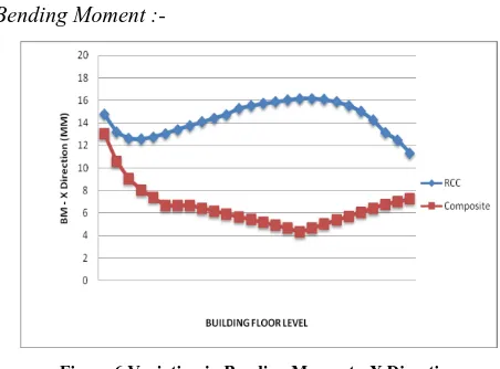
[image:5.612.327.553.376.543.2]Bending Moment :-
Figure 6 Variation in Bending Moment - X Direction
International Journal of Emerging Technology and Advanced Engineering
Website: www.ijetae.com (ISSN 2250-2459, ISO 9001:2008 Certified Journal, Volume 5, Issue 1, January 2015)
[image:6.612.59.278.122.269.2]206
Figure 7 Variation in Bending Moment Z Direction
[image:6.612.325.556.135.283.2]Axial Forces:-
[image:6.612.53.279.293.440.2]Figure 8 Variations in Axial Forces
Figure 8 Axial Forces for composite structural system is less as compared to RCC Structure.
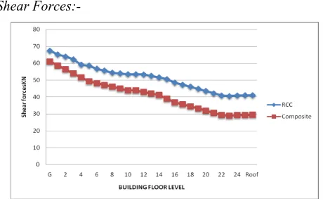
Shear Forces:-
Figure 9 Variation in Shear Force in X direction
The Figure 9 shows that the Shear force in R.C.C structure is on higher side than that of composite structure.
Cost Estimate :-
Figure 10 Cost Variations in RCC & Composite Structure
Figure 10 shows the Composite Structure is comparative cheaper than the RCC structure.
[image:6.612.329.556.330.482.2]Life Cycle Cost Estimate:-
Figure 11 Comparative of Life Cycle Cost Assessment
Figure 11 shows Life Cycle Cost for 30 yrs and 100 yrs for 8% and 12% discount rate shows cost of Composite structure is lesser than RCC Structure
VII. CONCLUSION
a. On analysis and study RCC column axial forces are
20% less as compared to Composite Structure.
b. Composite beam though posses heavy self weight but
its moment carrying capacity is 3 times more than the RCC structure.
c. Percentage of steel is within the permissible limit of
concrete, it indicates practically no shear as compared to RCC structure.
d. The cost comparison reveals that steel-concrete
[image:6.612.51.281.485.633.2]International Journal of Emerging Technology and Advanced Engineering
Website: www.ijetae.com (ISSN 2250-2459, ISO 9001:2008 Certified Journal, Volume 5, Issue 1, January 2015)
207
e. Analysis of Life cycle cost shows that the Composite
Structure is 13.7% cheaper in while assessment done at the discount rate of 8 % for 30 yrs , 13.90 % for 100 yrs @ 8%, 13.10% for 30 yrs @ 12% and for 100 yrs @12% found to be 13.15%.
REFERENCES
[1] Rehan, S., and Mahure, S.H., “Study of seismic and wind effect on multi-story RCC , steel and composite building” (International Journal of Engineering and Innovative Technology (IJEIT) Volume 3, Issue 12, June 2014 pp 78-83
[2] Wagh, Shweta A., and Dr. Waghe, U.P., “Comparative study of RCC and steel concrete composite structure” International Journal of Engineering Research and Application (IJERA), ISSN : 2248-9622, Vol. 4, Issue 4 (Version 1), April 2014, pp.369-376
[3] Koppad, Shashikala., and Itti, S.V., “Comparative Study of RCC and Composite Multi-storeyed Buildings” (International Journal of Engineering and Innovative Technology (IJEIT) November 2013 Volume 3, Issue 5, November 2013 pp. 341-345.
[4] Baldev, D. Prajapati., & Panchal, D. R.,“Study of seismic and wind effect on Multi Storey R.C.C., Steel and Composite Building” (International Journal of Advances in Engineering & Technology,) Vol. 6, Issue 4, Sept. 2013. ©IJAET ISSN: 22311963 pp. 1836-1847 [5] Panchal, D. R., and Marathe, P. M., “Comparative Study of R.C.C, Steel and Composite (G+30 Storey) Building” Institute Of Technology, Nirma University, Ahmedabad pp. 382- 481, 08-10 December, 2011
[6] Panchal, D. R., “Development of Program and Parametric Study of Various Composite Columns” (International Journal of Scientific Research) Vol : 3 | Issue : 8 | Aug 2014 • pp. 97-99 ISSN No 2277 – 8179
[7] Kumawat, M. S., and Kalurkar, L. G., “Cost Analysis Of Steel-Concrete Composite Structure” (International Journal of structural and Civil Engineering Research) ISSN 2319 – 6009Vol. 3, No. 2, May 2014 pp. 158-167
[8] Shah, Anish N., Dr. Pajgade, P.S., “Comparison of R.C.C. And Composite Multi-storied Buildings” (International Journal of Engineering Research and Applications (IJERA) Vol. 3, Issue 2, March -April 2013, pp.534-539 ISSN: 2248-9622
[9] LIU, Jingbo., and LIU. Yangbing., “Seismic Behavior Analysis Of Steel-Concrete Composite Frame Structure Systems” The 14th World Conference on Earthquake Engineering October 12-17, 2008, Beijing, China
[10] Begum,Mahbuba., Md. Serajus, Salekin., Khan, Tauhid Belal, N.M., and Ahmed, W., “ Cost Analysis Of Steel Concrete Composite Structures In Bangladesh” (Asian Journal Of Civil Engineering (BHRC)) Vol. 14, No. 6 (2013) Pages 935-944
[11] Panchal, D. R., and Patodi, S. C., “Response of A Steel-concrete Composite Building Vis-a-vis An R.C.C. Building Under Seismic Forces”
[12] Prof. Charantimath, S. S., Prof. Cholekar, Swapnil B., and M. Birje., “Comparative Study on Structural Parameter of R.C.C and Composite Building” (IISTE Civil and Environmental Research) ISSN 2224-5790 (Paper) ISSN 2225-0514 (Online) Vol.6, No.6, 2014 pp. 98-109.
[13] Holomek, J., Karásek, R., Bajer, and M., Barnat, J., “Comparison of Methods of Testing Composite Slabs World Academy of Science, Engineering and Technology (International Scholarly and Scientific Research & Innovation) Vol:6 2012-07-256 pp. 291-298
[14] Ambadkar, S. D., and Pajgade, P.S., “Design of Steel Frame Industrial Building Compared With Reinforced Cement Concrete Industrial Building” (International Journal of Scientific & Engineering Research), Volume 3, Issue 6, June-2012 1 ISSN 2229-5518 pp. 1-5
[15] Jutta Schade “Life Cycle Cost Calculation Models for Buildings” Department of Civil, Mining and Environmental Engineering Luleå University of Technology, Luleå, Sweden pp-1-9
[16] Da-Gang Lu and Guang-Yuan Wang “Risk based minimum Life-Cycle Cost design of seismic structures” The 14th World Conference on Earthquake Engineering October 12-17, 2008, Beijing, China.
[17] Y. K. Wen, and Y. J. Kang “Minimum building Life-Cycle Cost design criteria II: Applications” Journal Of Structural Engineering March 2001 ASCE, 127(3), pp. 338-346.
[18] Jagdishsingh, Real., S. Patil, Rahul., “Life Cycle Cost Estimation – Core Requirements” IOSR Journal of Mechanical and Civil Engineering (IOSR-JMCE) e-ISSN: 2278-1684, p-ISSN: 2320-334X, Volume 11, Issue 2 Ver. IV (Mar- Apr. 2014), pp. 40-42 [19] Johnson, R.P., “Composite Structures of Steel and Concrete” 3rd
Edition Backwell Publications.
[20] M.S Shetty, A Text Book on “Concrete Technology”
[21] State of Alaska - Department of Education & Early Development Juneau, Alaska, Alaska School Facilities “Life Cycle Cost Analysis Handbook” 1st Edition 1999
[22] Institute of Steel Development and Growth (INSDAG) “Multi-storeyed Residential Building [B+G+20] with Steel-Concrete Composite Construction” August 2010
[23] IS 456:2000 Indian Standard Code of Practice for Plain and Reinforced Concrete (Fourth Revision)
[24] SP: 16-1978 –Design Aid to IS: 456
[25] IS: 800-1984 (Reaffirmed in 1991) –Indian Standard Code of Practice for General Construction in Steel (First Revision)
[26] IS: 808-1989 Dimensions for Hot Rolled Steel Beam, Column, Channel and Angle Section.
[27] IS: 875-1987 (Part I to V) –Code of Practice for Design Loads (Other than Earthquakes) for Buildings and Structure.
[28] IS: 1893-1984 – Criteria for Earthquake Resistant Design of Structures
[29] IS: 1893-2005 – (Part -1)- Criteria for Earthquake Resistant Design of Structures
[30] IS: 11384-1985- Code of practice for Design for Composite Structures
[31] BS 5950-2000 Part -1 Code of Practice for Design –Rolled and Welded sections
[32] BS 5950-2000 Part -3 Code of Practice for design of Simple and continuous composite beams.
[33] EuroCode 3: Design of Steel Structure
[34] EuroCode 4: Design of Composite steel and Concrete Structure

![Figure 3 Steel-concrete composite column [22]](https://thumb-us.123doks.com/thumbv2/123dok_us/8704712.880399/3.612.76.262.113.291/figure-steel-concrete-composite-column.webp)
![TABLE DATA FOR ANALYSIS OF RCCI STRUCTURE : AS PER IS 456:2000 [23]](https://thumb-us.123doks.com/thumbv2/123dok_us/8704712.880399/4.612.324.564.289.599/table-data-analysis-rcci-structure.webp)