© 2017, IRJET | Impact Factor value: 5.181 | ISO 9001:2008 Certified Journal
| Page 70
DESIGN AND STRUCTURAL ANALYSIS OF DISC BRAKE BY USING CATIA
AND ANSYS-WORKBENCH
Sunkara Sreedhar
1, Parosh.G
21
PG Scholar,Mechanical Engineering,Chadalawada Ramanamma Engineering College, Tirupati,
Andhra Pradesh,India.
2
Asst.Professor,Mechanical Engineering,Chadalawada Ramanamma Engineering College, Tirupati,
Andhra Pradesh,India.
---***---Abstract:- The disc brake is a device for slowing or stopping
the rotation of a wheel. Friction causes the disc and attached wheel to slow or stop. Brakes convert friction to heat, but if the brakes get too hot, they will cease to work because they cannot dissipate enough heat. This condition of failure is known as brake fade. Disc brakes are exposed to large thermal stresses during routine braking and extra ordinary thermal stresses during hard braking. Actual disc brake has no holes; design is changed by giving holes in the disc break for more heat dissipation. An attempt is made in this project work to modeling and analysis of disc break first the disc break is modeling and meshing by using catia V5R20 and static and modal analysis is done by ANSYS 14.0 software by using four different materials like mildsteel, Aluminium, Castiron and composite material (e-glass).
Our main aim of the project is to compare the four materials which is having least deformation and less frequency and choose the best material which is suitable for designing the disc brake.
Keywords:CATIA,ANSYS WORKBENCH, mildsteel, Aluminium, Castiron and composite material (e-glass).
1. INTRODUCTION
Brake is a device by means of artificial frictional resistance applied to moving machine member, in order to stop the motion of vehicle. The energy absorbed by brakes is dissipated in the form of heat. This heat is dissipated in the form of atmosphere.
2. PRINCIPLES OF BRAKING SYSTEM
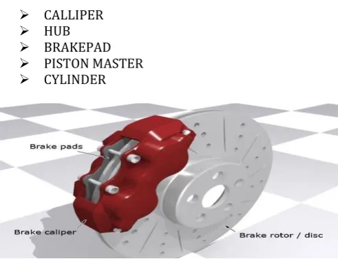
[image:1.595.316.578.249.385.2]When brakes are applied, hydraulically actuated pistons move the friction pads into contact with the disc applying equal and opposite forces on the disc. Due to the friction in between disc and pad surfaces, the kinetic energy of the rotating wheel is converted into heat which vehicle is to stop after a certain distance.
Figure 1 : Working principle of disc brake
2.1. COMPONENTS OF DISCBRAKE
CALLIPER HUB BRAKEPAD PISTON MASTER CYLINDER
Figure 2 : Components of disc brake
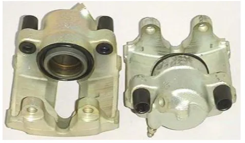
CALLIPER : A disc brake consists of a cast iron disc bolted to the wheel hub and a stationary housing called caliper.
HUB : It is the central part of the wheel, rotating on or with the axle and from which the spokes radiate.
[image:1.595.309.555.440.628.2]© 2017, IRJET | Impact Factor value: 5.181 | ISO 9001:2008 Certified Journal
| Page 71
PISTON : A disc or cylindrical part tightly fitting and movingwithin a cylinder either to compress the cylinder or expanding inside the cylinder into a rectilinear motion usually transformed into rotary motion by means of a connecting rod.
MASTER CYLINDER : It converts force to pressure. Pressure is used to move brake pads into the place.
2.2. TYPES OF DISCBRAKES
FIXED CALLIPER
FLOATING CALLIPER
SLIDING CALLIPER
[image:2.595.58.269.326.485.2]FIXED CALLIPER : It uses one or more pistons mounted on each side of rotor .The caliper is mounted rigidly and does not move.
Figure 3 : Floating Calliper
FLOATING AND SLIDING CALLIPER : Both designs are quite similar and are lumped together. The caliper which is not held in a fixed position, moves slightly bringing the outside pad into contact with rotor. The most common type of disc brake in modern cars is single floating caliper.
Figure 4 : Sliding Calliper
3. LITERATURE REVIEW
Talati and Jalalifar et al. (2009), presented a paper on Analysis of heat conduction in a disk brake system. In this paper, the governing heat equations for the disk and the pad are extracted in the form of transient heat equations with heat generation that is dependant to time and space. In the derivation of the heat equations, parameters such as the duration of braking, vehicle velocity, geometries and the dimensions of the brake components, materials of the disk brake rotor and the pad and contact pressure distribution have been taken into account. The problem is solved analytically using Green's function approach. It is concluded that the heat generated due to friction between the disk and the pad should be ideally dissipated to the environment to avoid decreasing the friction coefficient between the disk and the pad and to avoid the temperature rise of various brake components and brake fluid vaporization due to excessive heating.
Rotor Disc of Disc Brake by using new materials to improve braking efficiency and provide greater stability to vehicle. An attempt has been made to investigate the suitable hybrid composite material which is lighter than cast iron and has good Young’s modulus, Yield strength and density properties. Aluminum base metal matrix composite and High Strength Glass Fiber composites have a promising friction and wear behavior as a Disk brake rotor. The transient thermo elastic analysis of Disc brakes in repeated brake applications has been performed and the results were compared. Finally concluded that the suitable material for the braking operation is S2 glass fiber and all the values obtained from the analysis are less than their allowable values and brake Disc design is safe based on the strength and rigidity criteria
Telang A K, Rehman A, and Dixit G,Das S et.al (2013) investigated on alternate materials in automobile brake disc applications with emphasis on aluminium composites and have obtained the results that the friction coefficient of AMC is 25-30% times that of cast Iron and better wear characteristics ,the thermal conductivity of AMC can be two or three times higher than cast iron. An MMC disc could be 60 % lighter than an equivalent cast iron component. The Thermal Diffusivity, which is the rate of heat dissipation compared to that of storage, is four times that of castiron.
4. METHODOLOGY
[image:2.595.48.287.587.727.2]© 2017, IRJET | Impact Factor value: 5.181 | ISO 9001:2008 Certified Journal
| Page 72
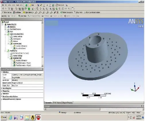
Figure 5 : CATIA model of Disc Brake4.1 Modelling of a Propeller:
Pad: On exit of sketcher mode the feature is to be padded (adding material)
Pocket: On creation of basic structure further pocket has to be created (removing material)
Revolve: Around axis the material is revolved, the structure should has same profile around axis.
Rib: sweeping uniform profile along trajectory (adding material)
Slot: sweeping uniform profile along trajectory (removing material)
Loft: Sweeping non-uniform/uniform profile on different plane along linear/non-linear trajectory
4.2 Fundamentals of FEA:
The finite element method is numerical analysis technique for obtaining approximate solutions to a wide variety of engineering problems. Because of its diversity and flexibility as an analysis tool, it is receiving much attention in almost every industry. In more and more engineering situations today, we find that it is necessary to obtain approximate solutions to problem rather than exact closed form solution. It is not possible to obtain analytical mathematical solutions for many engineering problems. An analytical solutions is a mathematical expression that gives the values of the desired unknown quantity at any location in the body, as consequence it is valid for infinite number of location in the body. For problems involving complex material properties and boundary conditions, the engineer resorts to numerical methods that provide approximate, but acceptable solutions. The finite element method has become a powerful tool for the
numerical solutions of a wide range of engineering problems. It has been developed simultaneously with the increasing use of the high- speed electronic digital computers and with the growing emphasis on numerical methods for engineering analysis. This method started as a generalization of the structural idea to some problems of elastic continuum problem, started in terms of different equations.
4.3 Meshing of Propeller Blade:
The solid model is transfer to the ANSYS WORKBENCH software.with the required commanding the mesh is generated for the model.Generally there two types of meshes are there ther are Tetrahedral Mesh.
(i) Hexahedral Mesh
The Tetrahedral mesh is a polygon consists of four triangular faces three of them are meet at a pointcalled as vertex.It has 6edges and 4 vertices.In case of hexahedral mesh it has 12 edges and 8 vertices.For the accuracy of the solution hexahedral gives the exact result.In the ANSYS software the internal command setting can be available for mesh generation.
Figure 6 : Fine meshed model of Disc Brake
4.4 Structrural Analysis:
[image:3.595.306.559.396.606.2]© 2017, IRJET | Impact Factor value: 5.181 | ISO 9001:2008 Certified Journal
| Page 73
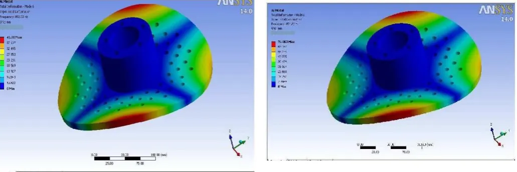
4.4.1 MILD STEEL MATERIAL [image:4.595.38.296.125.290.2]Figure 7 : Modal Analysis of Mild Steel
Figure 8 : Modal Analysis of Mild Steel with Pre-Stresses
Figure 9 : Modal Analysis of Mild Steel without Pre-Stresses
4.4.2 ALUMINIMUM MATERIAL
[image:4.595.286.556.305.495.2]Figure 10 : Modal Analysis of Aluminimum
Figure 11 : Modal Analysis of Aluminimum with Pre-Stresses
[image:4.595.39.285.323.504.2] [image:4.595.42.558.541.713.2]© 2017, IRJET | Impact Factor value: 5.181 | ISO 9001:2008 Certified Journal
| Page 74
4.4.3 CAST IRON MATERIAL [image:5.595.39.290.122.288.2]Figure 13 : Modal Analysis of Cast Iron
Figure 14 : Modal Analysis of Cast Iron with Pre-Stresses
Figure 15 : Modal Analysis of Cast Iron without Pre-Stresses
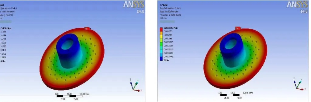
4.4.4 COMPOSITE MATERIAL
[image:5.595.47.559.330.499.2]Figure 16 : Modal Analysis of Composite Material
Figure 17 : Modal Analysis of Composite Material with Pre-Stresses
[image:5.595.67.549.546.724.2]© 2017, IRJET | Impact Factor value: 5.181 | ISO 9001:2008 Certified Journal
| Page 75
5. Results & Discussions
6. CONCLUSIONS :
It is concluded from the above study that using CATIA V5 R20 software design and modeling become easier. Only few steps are needed to make drawing in three dimensions, some can be imported to Ansys for analysis. Disc brake made of four different materials mild steel, all alloy, cast iron and composite material (e-glass) are analysed. Max pressure is found at the centre of disc brake. This is equal for all materials.
The disc brake is done on both static structural and modal analysis (with and without pre stresses). Depending upon on frequency and pressure values, the max frequency and pressure is found at Al alloy, and minimum frequency and pressure is found at composite material.
By comparing the above table, mild steel frequency and pressure will varies but the mild steel has good corrosive resistanceand the aluminimum values also increasing slightly but it has good thermal conductivity and the cast iron has good strength.
From the four materials e-glass has good properties and it has less frequency and less deformation. So, e-glass is the best material for designing the disc brake. Although e-glass has less deformation but it is costlier. If we reduce the cost of e-glass it is more economical to use with long life. Hence, composite material is suitable material for designing disc brake.
REFERENCES
[1] R.M. Wang and M.K. Surappa, Microstructure and interface structure studies of SiCp-reinforced Al (6061) metal-matrix composites Materials Science and Engineering. A, 254 (1-2), (1998), 219-226.
[2] Shaoyang Zhang, Fuping Wang, Comparison of friction and wear performances of brake material dry sliding against two aluminum matrix composites reinforced with different SiC particles, Journal of Materials Processing Technology 182 (2007) 122–127.
[3] T.F. Stephenson et al., Aluminum Hybrid Composites Containing Nickel-Coated Graphite Particulate, Processing, Properties and Applications of Cast Metal Matrix Composites, eds. P. Rohatgi and P.A. Khan (Warrendale, PA: TMS, 1996), pp. 337–351.
[4] Ashby M F. Materials selection in mechanical design. 3rd ed. UK: Butterworth Heinemann; 2005.
[5] Shanian A, Milani A S, Carson C, Abeyaratne R C. A new application of ELECTRE III and revised Simos’ procedure for group material selection under weighting uncertainty. Knowledge-Based Systems 21 (2008) 709–720.
[6] Jahazi M, Hossein-Nejad S. The development of an optimum manufacturing and material selection process for the fabrication of labyrinth seal strips. Journal of Materials Processing Technology 152 (2004), 272–275.
[7] Sapuan, S.M. Jacob, M.S.D. Mustapha, F. Ismail, N. A prototype knowledge-based system for material selection of ceramic matrix composites of automotive engine components, Materials & Design, Volume 23, Issue 8, (2002)701-708.
[8] Zhu, F., Lu, G., Zou, R. On the development of a knowledge-based design support system for energy absorber, Materials & Design, Volume 29, Issue 2, (2008), 484-491.
[9] Dieter G E, Engineering Design. 3rd ed. USA: McGraw-Hill; 2000.