© 2017, IRJET | Impact Factor value: 5.181 | ISO 9001:2008 Certified Journal
| Page 1171
Comparative CFD Analysis of Shell and Serpentine Tube Heat
Exchanger
Subin Michael
1, Kiran K John
2, Amal Krishnan
2, K K Shanid
2and Melnus Mathew
21
Assistant Professor,
Department of Mechanical Engineering, Vimal Jyothi Engineering College,
Chemperi, Kannur-670632
2
Department of Mechanical Engineering, Vimal Jyothi Engineering College, Chemperi, Kannur-670632
---***---Abstract -
Heat exchangers are the essential engineering
systems with wide variety of applications including nuclear reactors, chemical factories, refrigeration systems etc. In this study, we adopt a shell and tube heat exchanger having serpentine type tubes instead of separate straight tubes. ANSYS 16.2 Fluid Flow(Fluent) workbench is used to perform computational fluid dynamics (CFD) simulations. The heat exchanger geometry contains one serpentine tube of outer diameter 30 mm and shell of diameter 200 mm. In this paper, comparison is carried out by adopting different serpentine tube materials (ASTM A 179 Carbon steel and C12200 copper alloy). The changes in temperature profiles in each of the cases are taken into consideration for calculating effectiveness of heat exchanger. Better insights on optimal material selection for vital parts of a heat exchanger is obtained from comparative CFD analysis by adopting distinct industrial materials (ASTM A 179 Carbon steel and C12200 copper alloy).
Key Words:CFD, shell and tube, serpentine tube, heat exchanger, effectiveness
1.INTRODUCTION
Heat exchange can be occurred between fluids in motion. It is one of the most important physical process. A variety of heat exchangers are employed in different situations. For example, in air conditioning systems, nuclear plants, plywood companies etc.
The heat exchanger is intended to perform efficient heat transfer from one fluid to another. It may be either by direct contact or by indirect contact. In this study, a shell and tube heat exchanger equipped with serpentine shaped tube configuration is considered. Comparative CFD analysis is performed by adopting two different serpentine tube materials.
The two industrial materials adopted for study are C12200 copper alloy and ASTM A 179 Carbon steel. Different heat exchangers are named according to their area of implementation. For example, condensers are heat exchangers that are used to condense vapours, similarly heat exchanger for boiling of liquids are referred to as boilers. Effectiveness calculation is one of the technique for performance analysis of heat exchangers.
Usman Ur Rehman [1] studied the flow and temperature fields inside the shell and tubes. He resolved them using a commercial CFD package considering the plane symmetry. A set of CFD simulations is performed for a single shell and tube bundle and is compared with the experimental results. An un-baffled shell-and-tube heat exchanger design with respect to heat transfer coefficient and pressure drop is investigated by numerically modeling. Kwasi Foli [2], in his paper, describes two approaches for determining the optimal geometric parameters of the microchannel in micro heat exchangers. One approach combines CFD analysis with an analytical method of calculating the optimal geometric parameters of micro heat exchangers. The second approach involves the usage of multi-objective genetic algorithms in combination with CFD. Brahim Selma [3] carried out a study to develop an optimized heat pipe exchanger used to improve the energy efficiency in building ventilation systems. The optimized design is based on a validated model used inside a numerical plan built on a design of experiments statistical procedure. The numerical model, built using the open-source package OpenFOAM, is validated through experimental measurements done on a small-scale heat pipe industrial exchanger. The results from the open source model are also compared to the numerical predictions obtained from a commercial code.
Nawras H. Mostafa [4], Qusay R. Al-hagag Presented an approach to select the tube wall thickness distribution of streamlined tubes intended for use in heat exchangers is developed in this study. The main goal is to retain a streamlined outer profile (resist deformation) and to prevent strain failure due to the applied internal pressure. The effect of the tube wall thickness distribution on shaped tube efficiency is also considered.
© 2017, IRJET | Impact Factor value: 5.181 | ISO 9001:2008 Certified Journal
| Page 1172
1.1 Effectiveness, (ε) of a Heat Exchanger:
Effectiveness of a heat exchanger is defined as ratio of actual heat transferred to maximum possible heat that can be transferred. It denotes the degree to which heat exchanger is successful in producing desired heat transfer between different fluids. It is a parameter showing feasibility of a heat exchanger installation.
ε =
Substituting values of Qactual and Qmax possible from in general equation, we get;
ε =
=
2.CFD ANALYSIS
For any system, computational fluid dynamics (CFD) analysis starts with the construction of required geometry followed by mesh generation. Meshing is the discretization of the domain into small volumes where the governing equations are solved with the help of iterative methods.
Further modelling proceeds with assignment of boundary and initial conditions for the dominion and leads to modelling of the entire system. At the end of iterative solution steps, we can take the numerical and graphical output of the analysis.
2.1 Geometry:
First, the fluid flow (fluent) module from the workbench is chosen. It is a counter-flow heat exchanger. Heat exchanger geometry is built in the ANSYS Design Modeler. Naming of various parts may be done in this step.
[image:2.595.335.553.110.371.2]Fig -1: Main additional tube configurations used for shell and tube heat exchanger
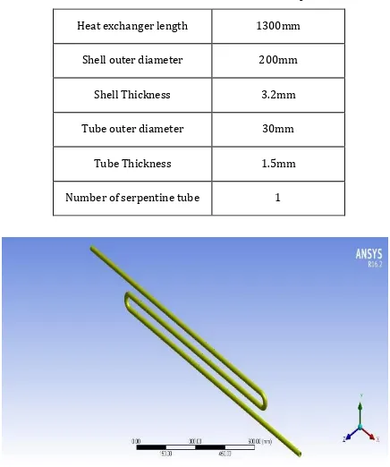
Table -1: Dimensions of Geometry
Fig -2: Isometric view of serpentine tube
Fig -3: complete model of shell and tube heat exchanger
2.2 Mesh:
Fig -4: Meshing diagram of shell and tube heat exchanger Heat exchanger length 1300mm
Shell outer diameter 200mm
Shell Thickness 3.2mm
Tube outer diameter 30mm
Tube Thickness 1.5mm
[image:2.595.336.551.393.531.2] [image:2.595.54.270.580.711.2]© 2017, IRJET | Impact Factor value: 5.181 | ISO 9001:2008 Certified Journal
| Page 1173
At first, a relatively coarser mesh is generated. Themesh contains tetra cells and hexahedral cells (i.e., mixed cells) having both triangular and quadrilateral faces at the boundaries.
Care is taken to employ structured hexahedral cells as much as possible. It is meant to reduce numerical diffusion as much as possible by structuring the mesh in a good manner, particularly near the wall region. In meshing stage, itself; named selections are specified like cold inlet, cold outlet, hot inlet, hot outlet etc. Heat transfer interfaces can be specified in this or it can be done in next stage of setup.
2.3 Fluent Setup:
The mesh is checked and quality is ensured. The analysis type is altered to Pressure Based type. The velocity formulation is assigned as ‘absolute’ and time to ‘steady state’. Energy option is set to ON. Viscous model is selected as “k-ε model”. The create/edit option is clicked to add water-liquid, copper, stainless steel, brass, ASTM A 179, C12200 materials to the list of fluid and solid respectively from the fluent database. But vast majority of the industrial alloys are unavailable in Fluent default data base. So, we have to create a user defined database ‘.scm’ file and use it for material assignment.
In each analysis, different parts of the heat exchanger geometry are assigned as corresponding fluid (eg: water) and solids (eg: copper, stainless steel etc.) as per the comparison criteria.
Boundary conditions are assigned according to the need of the model. The inlet conditions are defined as ‘mass flow inlet’ and outlet conditions are set as ‘outflow’. Two inlets and two outlets are defined by considering hot fluid side and cold fluid side.
Each wall is separately specified with respective boundary conditions. Each wall is set to no slip condition. Except the tube wall, other walls are set to zero heat flux condition.
Integral type surface monitor is assigned; field variable is selected as temperature. Surfaces like hot inlet, hot outlet, cold inlet and cold outlet are selected. It is useful in obtaining exact drop in temperature from inlet to outlet.
The details of boundary conditions are as follows:
Hot fluid inlet temperature (inner fluid),Thi= 365K Cold fluid inlet temperature (outer fluid), Tci=300K Hot fluid flow rate, mh=0.04 kg/s
Cold fluid flow rate, mc=0.05 kg/s
3.ANALYSIS RESULTS:
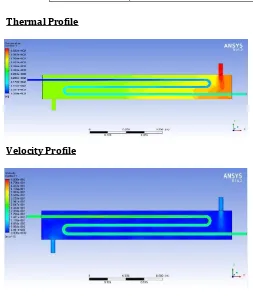
We have two cases considered in this comparative analysis. In case I, ASTM A 179 Carbon steel is assigned as inner tube material. In case II, C12200 copper alloy material is taken as the inner tube material case ll. In both cases, Stainless Steel is employed as the shell material.
Table -2: - CASE - I
Thermal Profile
[image:3.595.302.555.201.497.2]Velocity Profile
Table -3: -Tabulation of Results
Effectiveness Calculation
Heat capacity of cold water, Cc = mc * Cpc = 0.05*4179.725 = 208.98 W/K Heat capacity of hot water, Ch = mh * Cph = 0.04*4197.178 = 167.887 W/K
Inner material
Outer Material
ASTM A 179 Carbon Steel
Stainless Steel
Fluid Type
Mass flow rate, mc (kg/s)
Specific heat capacity,Cph (J/kgK)
Inlet Temp (K)
Outlet temp (K)
Cold
Fluid 0.05 4179.725 300 326.83
Hot
© 2017, IRJET | Impact Factor value: 5.181 | ISO 9001:2008 Certified Journal
| Page 1174
Ch < Cc, Cmin = ChEffectiveness,
ε =
=
[image:4.595.29.546.55.764.2]= 0.5138
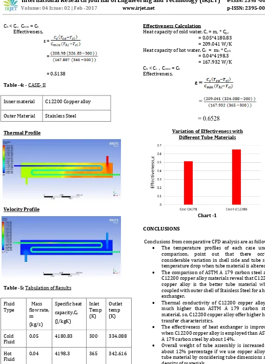
Table -4: - CASE- II
Thermal Profile
[image:4.595.308.539.65.512.2]Velocity Profile
Table -5: Tabulation of Results
Effectiveness Calculation
Heat capacity of cold water, Cc = mc * Cpc = 0.05*4180.83 = 209.041 W/K Heat capacity of hot water, Ch = mh * Cph = 0.04*4198.3 = 167.932 W/K Ch < Cc , Cmin = Ch
Effectiveness,
ε =
=
= 0.6528
Variation of Effectiveness with Different Tube Materials
Chart -1
CONCLUSIONS
Conclusions from comparative CFD analysis are as follows; The temperature profiles of each case under comparison, point out that there occurs considerable variation in shell side and tube side temperature drop when tube material is altered. The comparison of ASTM A 179 carbon steel and
C12200 copper alloy materials reveal that C12200 copper alloy is the better tube material when coupled with outer shell of Stainless Steel for a heat exchanger.
Thermal conductivity of C12200 copper alloy is much higher than ASTM A 179 carbon steel material, so, C12200 copper alloy offer higher heat transfer characteristics.
The effectiveness of heat exchanger is improved when C12200 copper alloy is employed than ASTM A 179 carbon steel by about 14%.
Overall weight of tube assembly is increased by about 12% percentage if we use copper alloy as tube material by considering tube dimensions and density of materials.
Inner material C12200 Copper alloy
Outer Material Stainless Steel
Fluid
Type Mass flow rate, m
(kg/s)
Specific heat capacity,Cp (J/kgK)
Inlet Temp (K)
Outlet temp (K)
Cold
Fluid 0.05 4180.83 300 334.088
Hot
© 2017, IRJET | Impact Factor value: 5.181 | ISO 9001:2008 Certified Journal
| Page 1175
Even if C12200 copper alloy tubes are better than A179tubes in a heat transfer point of view, the industrial material selection depends also on corrosion resistance, erosion, vibration behaviour, fouling, mechanical properties etc.
REFERENCES
[1] Usman Ur Rehman, “Heat Transfer Optimization of Shell-and-Tube Heat Exchanger through CFD Studies”, Chalmers University of Technology (2011)
[2] Kwasi Foli, Tatsuya Okabe, Marku Olhofer, Yaochu Jin and Bernhard Sendhoff, “Optimization of micro heat exchanger: CFD, analytical approach and multi-objective evolutionary algorithms”, International Journal of Heat and Mass Transfer (2005)
[3] Brahim Selma “Optimization of an industrial heat exchanger using an open-source CFD code”, Applied Thermal Engineering (2013)
[4] Nawras H. Mostafa, Qusay R. Al-Hagag, “Structural and Thermal Analysis of Heat Exchanger with Tubes of Elliptical Shape”, University of Babylon
[5] Daniel Flórez-Orrego, “Experimental and CFD study of a single-phase cone-shaped helical coiled heat exchanger: an empirical correlation”- Proceedings of ‘Ecos 2012’, June 26-29, 2012, Perugia, Italy
[6] J.S. Jayakumar, S.M. Mahajani, J.C. Mandal, P.K. Vijayan and Rohidas Bhoi, “Experimental and CFD estimation of heat transfer in helically coiled heat exchangers”, Chemical engineering research and design (2008)
[7] Dilpak Saurabh P, Harshal Khond and Mandar M. Lele, “CFD Analysis of a Triple Concentric Tube Heat Exchanger having water flowing at three different temperatures”, International Journal of Current Engineering and Technology (2016)
[8] Swapnaneel Sarma (2012), “CFD Analysis of Shell and Tube Heat Exchanger using triangular fins for waste heat recovery processes”, ESTIJ (2012)
[9] Dr.B. Jayachandriah, M. Uday Kumar, R. Jagaesh, T M Vamsi Krisha, “Fabrication and Design of Spiral Tube Heat
Exchanger”, American International Journal of