© 2017, IRJET | Impact Factor value: 5.181 | ISO 9001:2008 Certified Journal | Page 282
HELIUM BALLOON WINDMILL
Prithi seshadri
1, Dharmalingam.R
21
Anna University,Coimbatore,
2
Anna University,Coimbatore
2
ECE Head of the Department,Maharaja Institute of Technology,Coimbatore,Tamilnad
---***---Abstract – Creative thoughts of flying air machine has beenfamiliar with take up the greater enormity and all the more enduring rate with low inconsistency at higher tallness in the atmosphere."The NEXT GENERATION WINDMILL" is the exceptional time of turn turbine with noteworthy cost and better over existing structures. It is the air attached wind swell that turns equally in light of the wind. Helium Sustains the system to a height with the help of the weight sensor. My paper prescribes a differentiating alternative to beat the drawback of existing system. The damage of air borne system is energetically given .There are chances of broken relationship between flying inflatable and ground structure. The thought of Controller wing and blasting system move beyond the disadvantage.
Key Words: Air Rotor system,Magnus effect,Airborne
system,Helium Gas,Eco friendly.
1.INTRODUCTION
In the developing science and innovation, renewable vitality put an essential part. The creation of different renewable vitality like Tidal, Wind and Solar has demonstrated a shelter to humankind. In this paper the power era utilizing renewable vitality with ECO agreeable system is examined. The extent of this venture is to dispense with the impracticable of kite-based frameworks and cutting edges by making a recoverable, adaptable, easy to use unmanned flying vehicle (UAV) utilizing Helium inflatables.
Routine wind vitality authorities which incorporates Horizontal hub machines like dutch sort wind plant and vertical hub machines like Darreus rotor.
Disregarding different preferences these machines experience the ill effects of different disservices like
self-ruling retraction.My paper recommends about the disposal of fastened wing and it is supplanted with helium filled inflatable
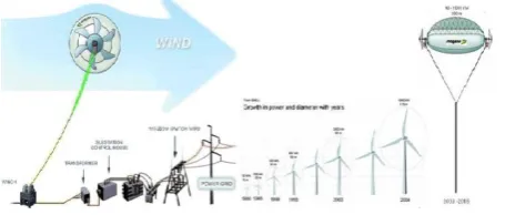
Fig 1. .Helium balloon System
2. AIR ROTOR SYSTEM
Air Rotor framework depends on the standard of Magnus Effect has been proposed and elevate of Helium gas producing 4 kW appraised power.It would be moored by the tether that can broaden upto 1000 feet from ground.A tallness of 400 feet can get the twist at the speed of 3 m/s ,The inflatable twists noticeable all around turning the generators.The pivot balances out the inflatable while the vitality is exchanged to the ground through the inflatable,
The Air Rotor System is a lighter than air fastened wind swell that pivots about a level hub because of wind, creating electrical vitality. The electrical vitality is to be exchanged down the 1,000 feet tie for prompt utilize, or to an arrangement of batteries for later utilize, or to the power network.
[image:1.595.308.536.268.365.2]© 2017, IRJET | Impact Factor value: 5.181 | ISO 9001:2008 Certified Journal | Page 283
3.MAGNUS EFFECT
A spinning object is moving through the fluid departs from its straight path because of the pressure differences that develop in the fluid as a result of velocity changes induced by spinning body.The Magnus effect is the manifestation of Bernoulli’s theorem fluid pressure decreases at points where the speed of the fluid increases.In case of ball spinning through the air,the turning ball will drag some of the air with it.Viewing the position of the ball ,the air is rushing by all the sides.The drag of the side of the ball turning into the air retards the air flow whereas the drag on other sides speeds up the air flow.A large object similar to that of the air rotor creates substantial lift, so much so that the device should actually work in a wind stream, without using a lifting gas like He.
Fig 2, Floating air system
Fig -3: Magnus effect
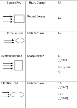
4.LEAST DRAG GEOMETRIC SHAPES
Square Rod Sharp Corner
Round Corner
2.2
1.2
Circular Rod Laminar flow 1.2
Rectangular Rod Sharp corner 1.3 (L/D=3
2.5(L/D=0. 5)
Elliptical rod Laminar flow 0.6 (L/D=2)
0.25 (L/D=8)
Tab 1
.Geometric figures
From the recorded figures, we pick the "elliptical pole" this shape will help us to keep up minimum drag condition and movement, however, this drag condition alone is not adequate for keeping inflatable stationary and subsequently we formulated an examination in which we created an opening in focal point of the inflatable going through its horizontal pivot which permits air to go through. The nearness of opening keeps up the inflatable in a stationary position for a longer time frame as the wind will dependably attempt to take the easiest course of action i.e. it will dependably attempt to go through the entry and henceforth the inflatable will dependably confront towards the course of wind.
[image:2.595.304.563.151.515.2] [image:2.595.36.265.352.470.2]© 2017, IRJET | Impact Factor value: 5.181 | ISO 9001:2008 Certified Journal | Page 284
inflatable in different introductions when the windpassage was exchanged on the inflatable situated itself in course of the wind and further revolution was smothered. The pivot and arrangement of the inflatable with the course of wind was the weight distinction between two unique sides of the inflatable. This is a direct result of the nearness of a section of twist through the opening in the inflatable which brings down the pressure next to its by increasing the wind speed and hence it rotates the balloon in the opposite direction to stabilize the pressure.
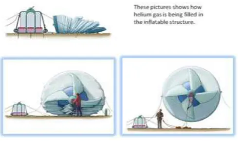
5.USAGE OF HELIUM GAS
The air rotor is loaded with He gas, which is dormant and non-combustible. The lifting Helium gas makes a lift compel that is in overabundance of the aggregate weight of the framework. The He gas gives at any rate double the positive lift contrasted with the general weight of the unit. The turning of the rotor makes an extra lift.. The streamlined impact that delivers extra lift is the Magnus Effect.To keep rotor at an altitude,the helium gas assumes a noteworthy part. The gas is likewise copious, cheap and ecologically protected.
The consolidated lifting impact from the light He lift and streamlined Magnus lift settles the air rotor against inclining in the wind. In view of the test done, an air rotor went straight up and held a close vertical position in different twist speeds, as the Magnus impact increments as the wind speed increments. Most extreme lean is required to be under 45 degrees from the vertical.
The 4 kW appraised control unit would requires marginally more than 6,000 cubic feet of He. Helium spills at a rate of 0.5 percent for every month or 6 percent for every year, hence the air rotor units should be finished up with He each four to six months.
Fig 4 Helium inflated balloon
6.POWER GENERATION
In the presence of high winds, floating rotor is capable of exerting a traction force equivalent to several hundred kilo Newtons, moving at speeds that can exceed 80 m/s. The product of the force multiplied by the speed provides to the order of magnitude of the potential power generated by the kite:
P = F .V [Eq--1]
A single balloon has the theoretical potential at a speed of 80 m/s and a force of 100,000 Newtons of generating a power of:
P ≈ 100x103.80 ≈ 8x10⁶[Watt] = 8[MW ] [ Eq--2]
which exceeds the rated power of existing horizontal axis wind turbines at 7 MW.
The floating wind generator can be envisioned as a giant carousel, solidly anchored to the ground. Its nucleus consists of a central structure, tall enough to support the arms by means of a tenso structure. This carousel is put into motion by the wind itself that drag the wind rotor out from their funnels within the arms, and into the sky. The rotating central structure contains the automatic winches that control the pairs of cables of thousands of meters in length.Cables made of high strength materials such as Dyneema have a tensile strength that is capable of holding 30 tons/cm2, and these cables weigh just 100 kg/km.The
applications of the air floating rotor are stated,Off grid for cottages and remote uses such as cell towers and exploration equipment); Developing nations where infrastructure is limited or nonexistent;Rapid deployment (to include airdrop) to disastrous areas for power to emergency and medical equipment, and relief efforts (ex. Katrina, Tsunami) and military applications.
7.HELIUM BALLOON DESIGN
[image:3.595.40.285.588.733.2]© 2017, IRJET | Impact Factor value: 5.181 | ISO 9001:2008 Certified Journal | Page 285
screen the weight Once the weight comes to beneath themaximum furthest reaches of the lift, the helium pressurized gas container will be encouraged with an order by the weight sensor and after that helium will be refilled in the inflatable. For around 30 - 50 days,this whole framework will keep the inflatable noticeable all around. This inflatable is composed in such way that it can be refilled and reused.[5]
Fig.4.1 Cylindrical balloon Skeleton
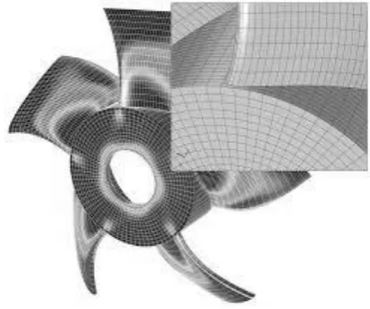
8. MODELLING USING COMPUTATIONAL FLUID
ANALYSIS
[image:4.595.65.272.397.570.2]
Fig 4.2.FLOATING BALLOON IN CFD
This modeling is done with the help of CFD(Computational Fluid Dynamics).This tool is applied for resolving different fluid flow related problems like flow velocity, density, temperature, and chemical concentrations for any area where flow is present. It’s a numerical method for calculation for nonlinear differential equations describing/relating to fluid flow.
Fig. 5 Tethering system
9.CONSTRUCTION AND WORKING:
The wind turbine is a lighter-than-air tethered wind turbine that rotates about a horizontal axis in response to wind, generating electrical energy. This electrical energy is transferred down the tether for consumption.
9.1.Cylindrical Balloon: -
The balloon is cylindrical in shape and is filled with helium air which is lighter then air, hence it could be placed above 300m height.
Wind vane stabilizer: - It is one of the important parts of the air borne turbine. It restricts the turbine in horizontal direction, and gives stability to the balloon.
9.2. Axle:
It acts as a frame of turbine which is a single shaft connecting the balloon, and aluminum tube to the generator shaft, hence it is the power transferring element of the air floating turbine.
9.3.Generator:
It the actual machine which converts the rotary motion into electrical energy. There are two conventional generator used for power generation. And transfers power to the base station unit.
9.4.Pressure Sensors: (inside the balloon)
Pressure sensor will keep a track of pressure drop and reduction in the gas quantity within the balloon. Once the weight comes to underneath the maximum furthest reaches of the lift, the helium pressurized gas bottle will be fed with a command by the pressure sensor and then helium will be refilled in the balloon. For approximately 30 - 50 days,this entire system will keep the balloon in the air. This balloon is designed in such way that it can be refilled and reused.[5]
9.5.Locking system:
© 2017, IRJET | Impact Factor value: 5.181 | ISO 9001:2008 Certified Journal | Page 286
Fig 5 Flying Wind MillFig 6.Rotor model Fig.6 Cylindrical balloon
9.COMPARISON WITH HORIZONTAL TURBINE.
The wind rotor cleared region is exceedingly stressed for a level plate wind turbine.In the occasion of the wind rotor, one can grow the measure of the rotor at little cost and better fiscal adequacy per unit of cleared area.The air rotor can work at a speed more conspicuous than 28 m/s.Thus the unit uses the Magnus effect.The auxiliary trustworthiness assumes an indispensable part in augmenting the speed.The air rotor size is particularly with respect to the speed capability.The exorbitant speed is controlled by directing the tie height.[2]
The crumple is typical on all aircrafts is an emergency structure that would be used in case it for no good reason the rotor broke free or other unprecedented emergency.
The generator bolsters the hub closes however underneath the axle,they go about as tie grapple points.The incorporation of basic apparatus framework expands the revolution speed.
10. SPECIFICATIONS OF 4 KW AIR TURBINE:
11. RESULTS AND DISCUSSION
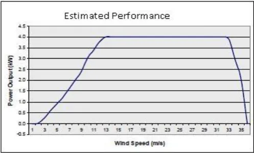
Chart 1: Simulated graph power output Vs Wind speed
Fig 7 The Simulated graph is obtained from the software .From the graph it is verified that the power output of the floating air balloon increases exponentially as the wind speed increases.As the flow of wind is considerably high at higher altitude.
12. CONCLUSION
Helium filled inflatable is extremely easy to install.Despite of its bigger size ,no cranes are required to send the framework. High‐altitude wind control utilizing fastened wind turbine gadgets can possibly open up another twist asset in territories that are not served by customary turbines.Thus the likelihood of broken association is corrected by the locking framework been presented
EQUIPMENT WEIGHT
Balloon 4 kg
Helium Refilling
System(27CF, 1800psi)
3 kg
Tethered rope (Kevlar, 450Kg tensile strength)
4.46 Kg per Km
Start up wind speed 1m/s
Rated wind speed 12.5 m/sec
[image:5.595.311.557.126.338.2] [image:5.595.310.559.395.545.2]© 2017, IRJET | Impact Factor value: 5.181 | ISO 9001:2008 Certified Journal | Page 287
13.REFERENCES
[1] Kamini.N.Shelke,”Magenn Air Rotor System(MARS)”,vol no:2,Issue 6,December 2012.
[2] Rakesh Chaudari,”Electric Energy Generation by MARS”Vol no 4,issue 2,April 2015.
[3] Aldo U Zgraggen,”Automatic Retraction and Full Cycle Operation for a Class of Airborne Wind Energy Generators”,IEEE transactions on control system technology,”vol 24,no 2,March 2016.
[4] S.Ramya,”Flying Windmill”,IJARSE,Vol no 4,special issue (02),Feb 2015.