© 2017, IRJET | Impact Factor value: 5.181 | ISO 9001:2008 Certified Journal | Page 2679
DIGITAL AVERAGE CURRENT SHARING CONTROL FOR LOW VOLTAGE
DC MICROGRIDS
Anuja Ann Mathews
1, Veena Mathew
2, Geethu James
31PG Scholar, Dept. of EEE, Mar Athanasius College of Engineering, Kothamangalam, Kerala, India 2Assistant Professor, Dept. of EEE, Mar Athanasius College of Engineering, Kothamangalam, Kerala, India 3Assistant Professor,Dept. of EEE, Mar Athanasius College of Engineering, Kothamangalam, Kerala, India
---***---Abstract -
As compared to AC system, DC microgridshave high efficiency, high reliability, and easy interconnection of renewable sources. DC microgrid should be controlled in such a way so as to ensure proportional load sharing among sources and also to maintain low voltage regulation of the system. Conventional droop controllers are not effective in achieving both the above mentioned objectives simultaneously. Even though centralized controller satisfies these objectives, it requires high speed communication and offers less reliability because of single point of failure. In this paper a decentralized controller for dc microgrid is explained. Key advantages are high reliability, low voltage regulation, and proportional load sharing. Simulation of both decentralized controller and droop controller is carried out in MATLAB.
Key Words: DC microgrid, Droop controller, ACS control, DACS control, Decentralized controller .
1. INTRODUCTION
Distributed power generation systems are gaining popularity due to increasing energy demand. High reliability, remote electrification, low distribution losses, reduced chances of blackout and easy scalability are the key advantages of the distributed systems[1]. Microgrid includes the control and coordination of distributed generation and storage units to maintain power balance between sources and loads. The control objectives of DC microgrid are to ensure equal load sharing in per unit among sources and also to maintain low voltage regulation of the system[4]. There are different control strategies for DC microgrid. Droop controller, Average current sharing (ACS)control etc are some of the controllers for DC microgrid.Conventional droop controllers are not effective in achieving both the
control objectives of DC microgrid
simultaneously[5]. Reasons for this are identified to be the error in nominal voltages and load distribution. Though centralized controller achieves
these objectives, it requires high speed
communication and offers less reliability due to single point of failure. In this paper a comparison of droop controllers and Digital average current sharing control schemes are explained.
2. DROOP CONTROLLER
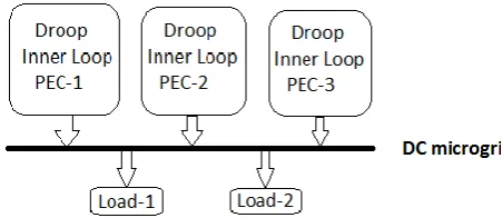
Figure 1 shows the block diagram of droop controller. Each source is represented using a power electronic converter (PEC).For each source there is a droop control and an inner voltage and current control loop.
Figure1.Block diagram of droop controller
There is no secondary control. For dc systems, droop between voltage and current is given by
v
jref= v
j0- d
ji
j ……….(1)where dj, ij and vj0 are the droop gain, source current,
reference voltage and nominal voltage of source j respectively. As there is no secondary control, parameters of the droop control are set such that system voltage is maintained within the specified value. Inorder to ensure low-voltage regulation, low value of droop gain dj should be used. Figure 2 shows
the steady state equivalent circuit of DC microgrid. For two parallel connected DC sources, unequal load sharing due to small error in nominal voltages is shown in figure 3. In case of small droop gain, the deviation in source current, i.e., ( i1- i2 ), is large. As
[image:1.595.314.540.408.506.2]© 2017, IRJET | Impact Factor value: 5.181 | ISO 9001:2008 Certified Journal | Page 2680 However, the voltage regulation is large and may not
be acceptable to loads. Therefore, use of droop controllers are not effective in low-voltage DC microgrids.
2.1. Simulation Results
Simulation is carried out in MATLAB. Here four sources are considered and there is a remote load. Each source is represented using a boost converter. Each converter is designed for an output of 400 V. These four sources are supplying a remote load. An ideal switch is connected across the remote load for load variations. PI controller is used for inner voltage and current loop of boost converter. Droop gain dj is
1.9 Ω.
2.2. Tabulation of Results
Each converters output voltage and current sharing in per unit for constant load is tabulated in table 1. Voltage regulation and current sharing error is calculated.
[image:2.595.312.570.103.304.2]Figure 2. Steady state equivalent circuit of DC microgrid
Figure 3. Droop characteristics
[image:2.595.310.564.334.515.2]Figure 4. Simulink model of droop controller for DC microgrid
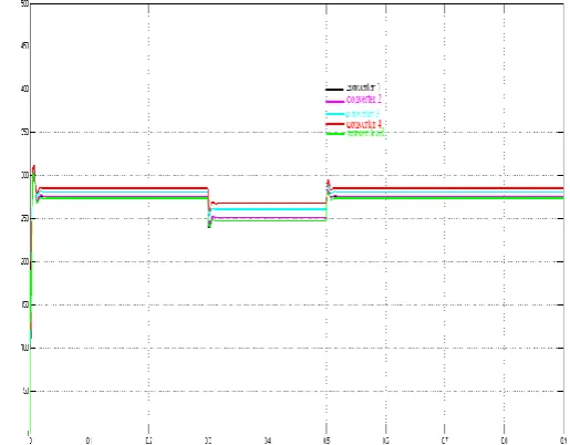
[image:2.595.50.285.495.656.2]Figure 5. Converter output voltages
© 2017, IRJET | Impact Factor value: 5.181 | ISO 9001:2008 Certified Journal | Page 2681 CONVE
RTER O/P VOLTG
AE(V)
REGULATI
ON(%) O/P CURRE
NT(in per unit)
CURR ENT SHAR ING ERRO R IN %
1 275.6 31.1
0.5238 3.20
2 276.4 30.9
0.5208 2.68
3 281.1 29.7
0.5006 1.30
4 285.2
28.7
0.4836 4.65
Remote Load
273.1
31.7
-
-
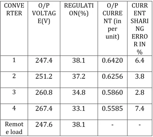
Each converters output voltage and current sharing in per unit for variable load is tabulated in table 2. Voltage regulation and current sharing error is calculated.
CONVE
RTER VOLTAGO/P E(V)
REGULATI
ON(%) CURREO/P
NT (in per unit)
CURR ENT SHARI
NG ERRO
R IN %
1
247.4
38.1
0.6420
6.4
2
251.2
37.2
0.6256
3.8
3
260.8
34.8
0.5860
2.8
4
267.4
33.1
0.5585
7.4
Remot
e load
247.6
38.1
-
-
As large value of doop gain is chosen voltage regulation is poor but the error in current sharing is less. Under constant load, maximum value of
regulation is 31.7% and the maximum value for error in current sharing is 4.65%.
3. DIGITAL AVERAGE CURRENT SHARING (DACS)CONTROL
For droop controllers, large value of droop gain ensures equal load sharing but voltage regulation is poor. DACS control scheme helps to overcome this limitation. Droop characteristics gets shifted along the voltage axis by addition of ∆vj0 in the
conventional droop equation and is given by
v
jref= v
j0+∆v
j0-d
ji
j……….(2)To determine the value of voltage shift ∆vj0 a
low-bandwidth communication is utilized. The controller of each source communicates with the controller of other sources and sends the magnitude of current supplied (in per unit) by it. Using this information, the individual source controller determines the average value of the current supplied by all the sources using
∑
………(
3)where impu is the source -m current in per unit. Shift
in droop of each source is set according to their calculated average current as follows
∆v
j0= k
ji
javgi
jrated………..(4)
where kj and ijrated are the shift gain and rated
current of source j respectively. For change in load, sources continue to share the demanded power equally due to large droop gains. Instantaneously, system voltage may vary from its nominal value due to the change in source current. It is restored once the new values of currents are communicated among sources and new value of voltage shifts ∆vj0 are
[image:3.595.44.292.147.376.2]calculated. This shift control is called as digital average current sharing (DACS) control.
[image:3.595.30.286.490.718.2]Table 1. Converter output voltages and current during constant load
Table 2. Converter output voltages and current during variable load
[image:3.595.311.506.618.728.2]© 2017, IRJET | Impact Factor value: 5.181 | ISO 9001:2008 Certified Journal | Page 2682 3.1. Simulation Results
Simulation parameters are similar to droop controller. Here shift gain kj is chosen as 1.8 Ω.
3.2. Tabulation of Results
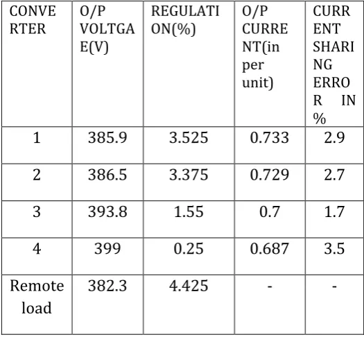
Each converters output voltage and current sharing in per unit for constant load is tabulated in table 3. Voltage regulation and current sharing error is calculated.
Each converters output voltage and current sharing in per unit for variable load is tabulated in table 4. Voltage regulation and current sharing error is calculated.
Under constant load, maximum value of regulation is 4.425% and the maximum value for error in current sharing is 3.5%. Simulation results shows that DACS CONVE
RTER
O/P VOLTGA E(V)
REGULATI ON(%)
O/P CURRE NT(in per unit)
CURR ENT SHARI NG ERRO R IN %
1
385.9
3.525
0.733
2.9
2
386.5
3.375
0.729
2.7
3
393.8
1.55
0.7
1.7
4
399
0.25
0.687
3.5
Remote
load
382.3
4.425
-
-
CONVE RTER
O/P VOLTGA E(V)
REGULATI ON(%)
O/P CURRE NT(in per unit)
CURR ENT SHARI NG ERRO R IN %
1
375
6.25
0.975
6.6
2
380
5
0.95
3.8
3
395
1.25
0.883
3.4
4
404.8
1.2
0.85
7
Remote
load
[image:4.595.302.565.130.373.2]375
6.25
-
-
Figure 8. Simulink model of DACS control for DC microgrid
[image:4.595.36.555.132.648.2]Figure 9. Converter output voltages
Figure 10. Converter output currents in per unit
Table 4. Converter output voltages and current during variable load
[image:4.595.39.279.164.320.2] [image:4.595.287.563.417.662.2]© 2017, IRJET | Impact Factor value: 5.181 | ISO 9001:2008 Certified Journal | Page 2683 control scheme satisfies the two control objectivesof
DC microgrid. When compared with droop controller, DACS control scheme has better performance.
4. CONCLUSIONS
Digital average current sharing control scheme ensures proportional load sharing and improve voltage regulation in low voltage dc microgrids. The control is based on the droop control method together with a decentralized average current sharing control. The droop control is a local
controller, which does not require any
communication system, and achieves good current sharing at the expense of compromising the voltage regulation. Also, the voltage is not constant in the microgrid. Therefore, the current sharing is hard to achieve when distance between sources is considerable. DACS control overcomes this drawback. Simulation results of DACS control shows that under constant load conditions voltage regulation is less than 4.5% and the error in current sharing is less than 4%.
.
REFERENCES
[1] S.Anand,B. G. Fernandes, “Optimal voltage level for DC microgrids", IEEE Ind.Electron Soc. Conf. , November 2010.
[2] S.Anand,B. G. Fernandes, “Steady state performance analysis for load sharing in DC distributed generation system", in Proc. 10th Int.Conf. Environ. Electr. Eng.,May 2011 pp.1-4.
[3] H. Kakigano, Y. Miura,T. Ise, “ Low-voltage bipolar- type DC microgrid for super high quality
distribution ", IEEE Trans. Power Electron.,VOL.25, NO.12 December 2010.
[4] R.Majumder, G. Ledwich, A. Ghosh, S. Chakrabarti,F. Zare, “Droop control of converter-interfaced microsources in rural distributed generation",IEEE Transactions On Power Del.,VOL. 24, NO.4, October 2010 pp. 2768-2778.
[5] S. V. Iyer, M. N. Belur,M.C. Chandorkar, “A generalized computational method to determine stability of a multi inverter microgrid",IEEE Trans. Power Electron.,VOL. 25,NO. 9,September 2010, pp. 2420-2432.
[6] D. Guezgouz, D. E. Chariag, Y. Raingeaud,J.-C. Le Bun, “Modeling of electromagnetic interference and PLC transmission for loads shedding in a