item and our policy information available from the repository home page for further information.
Author(s):Saidpour, Hossein
Title:Finite element stress analysis of a hybrid fracture fixation plate Year of publication:2006
Citation:Saidpour, Hossein (2006) ‘Finite element stress analysis of a hybrid fracture fixation plate’ Proceedings of Advances in Computing and Technology, (AC&T) The School of Computing and Technology 1st Annual Conference, University of East London, pp.173-183
Link to published version:
FINITE ELEMENT STRESS ANALYSIS OF A HYBRID
FRACTURE FIXATION PLATE
Hossein Saidpour
Design and Manufacturing Research Group S.H.Saidpour@uel.ac.uk
Abstract: Metal plates are commonly used in the operative treatment of bone fractures (Figure 1). Rigid metal plates stabilise the fracture site, maintain good contact between bone fragments. However, treatment with rigid metal plates can cause localised bone atrophy due to stress shielding and interference with blood circulation, and the weakened bone can refracture after plate removal.
A carbon fibre reinforced plate system that combines the torsional and bending rigidity of a metal plate with the axial compliance of a polymer insert has been designed. A three-dimensional, quarter-symmetric finite element model was generated for a canine femur diaphysis plated with this metal/polymer hybrid design. A model with a standard metal fixation plate was also generated for comparison purpose. The stress state in the underlying bone was examined for several loading conditions taken from published in vivo studies. The finite element model was used to study the performance of biodegradable polymer inserts in the plate system. The flexible plate reduced stress-shielding effects at the fracture site when subjected to an axial load. The bending strength of the plate was not compromised by the addition of the polymer inserts. Biodegradable inserts further enhanced the performance of the new plate design, transferring less of the axial load to the plate as the inserts broke down.
1. Introduction
The healing of a fracture in the forearm can be assisted by screwing a fracture plate across the fracture site. Internal fixation with rigid metal plates, screws and pins is a proven operative technique for the treatment of bone fractures. Internal fixation hardware provides excellent reduction of the bone fragments and has the necessary strength to stabilise and support the fracture, allowing early mobility of the forearm. The early fixation plates were made from 306 or 316 stainless steel due to their good corrosion resistance. However, orthopaedic industry has closely followed the aerospace industry in utilising high performance metal alloys, based on Cobalt-Chromium and Titanium alloys, with an elastic modulus 10 times that of bone, for superior implant performance
and might be on the road to repeating this with advanced composite materials.
the diameter of the bone and inhibits normal bone remodelling as evidenced by the persistence of immature woven bone. A significant number of refractures has been reported after removal of rigid internal metallic plates, as a result of this alteration in bone physiology.
Mechanical stimulus or stress in the skeleton is a major factor in maintaining the normal balance between the processes of bone formation and bone resorption. When physiological stress is diminished, osteoporosis occurs rapidly. Stress shielding occurs when two or more components with different moduli form one mechanical system. The component with the higher modulus bears more of the load and protects the other fixation devices. Although at first the rigid fixation may favour primary bone healing, the stress shielding during the later stages of healing may lead to osteoporosis with decreased bone strength (5). The degree of stress shielding is related to the rigidity of fixation (6). The actual force acting across the bone and fracture, as well as the stress concentrations in the bone depend on the dimensions and shape of the fixation device (7).
Several in vivo studies have shown the stress shielding effects resulting from the use of rigid internal fixation plates (5, 4). Mechanical changes due to internal fixation are a result of reduction in cortical bone structure by thinning of the cortex rather than by a reduction in the bone substance’s mechanical properties (9). There is an initial general resorption of bone tissue followed by a reversal of the remodelling process and then long term, site-specific bone resorption. Reducing the stiffness of the device should enhance fracture healing, but a compromise must be reached between strength and stiffness as flexible plates with inadequate strength can cause pain and can result in non-union of the fracture (10).
Several alternative plate designs and plate materials have been proposed to minimise the effects of stress shielding. Uhthoff et al (11) compared the results obtained with stainless steel plates and titanium alloy plates. The titanium plates were as strong as the steel plates, but were half as stiff. They observed less stress-shielding induced bone loss with titanium. Whereas with stainless steel there was a haphazard arrangement of bone lamellae and osteons at the fracture site, often at right angles to the long axis of the bone. In the bone fixed with titanium plates, however, the compact bone at the fracture site had a nearly normal histological structure.
Woo et al (12) proposed a tubular stainless steel plate that had high bending and torsional stiffness to ensure adequate fragment control, but a low axial stiffness to allow the underlying bone to carry a higher portion of the load in the post-union phase of healing. Woo et al (12) compared the performance of a standard stainless steel plate, a thin titanium plate and the tubular stainless plate and observed similar results for the tubular plate and the titanium plate. However, the tubular plate had a much higher bending and torsional stiffness than the thin titanium plate and would provide much better fragment control in the pre-union phase of healing. The less flexible plates allowed the development of an external callus at the fracture site, which was much more robust than bone formed by direct remodelling.
composites have been developed. In responding to the complex demands on fracture plates, the use of advance composite materials potentially would enable designs that can seek optimal mechanical characteristics through modifications of fibre types, orientation and ply-stacking sequences, as well as implant geometry (15). The experimental and clinical results have so far demonstrated some limitations of these new materials (16). Disadvantages of carbon fibres embedded in epoxy, polyester or PMMA include; a) long term reduction in properties sometimes before bone healing has been completed, interaction of body fluids with the matrix material may degrade the properties, b) the release of carbon fibre fragments that can migrate into other tissues (17), c) lack of ductility that prevents reshaping in the operating room in the manner of metal implants (18). The latter problem can be overcome by selecting an alternative matrix polymer such as polysulphone, which can be reshaped to the required size, under moderate heat, in the operating room (19).
In a recent investigation (15) to compare deformation behaviour of composite fracture plates made from aramid-epoxy and carbon-epoxy composites, in which 4-hole fracture plate specimens were used, it was shown that the aramid composites appeared to be less subject to catastrophic failure than carbon fibre composites. Also when the specimens were fastened to a plastic tube, simulating bone, the strain shielding was significantly reduced by the aramid composites relative to carbon fibre composites. Claes (20) conducted an extensive study of fracture behaviour of 6-hole plate design made from carbon fibre reinforced carbon composite. It was concluded that bending and torsional rigidities of the plate over the fracture zone must be sufficient to prevent gross motion at
the fracture site, however the axial stiffness, bending and torsional rigidities must be reduced to minimise stress protection.
In order to optimise the fixation stiffness/ strength and study the effect of different fracture plate properties on the healing process Foux et al developed an experimental device called the “axially flexible plate” (AFP) system (21). The system consisted of three components: a rigid metal plate, screws and elastic inserts. The elastic inserts made of various, biocompatible polymers such as poly-methylmethacrylate (PMMA), low density polyethylene (LDPE) and poly-L-Iactide (PLLA) fill the space between the screws and the metal plate in the plate's elongated holes. The screws can move laterally towards the fracture site by deforming the cushions. The axial flexibility of the AFP depends on the insert elasticity.
The animal trials were conducted with the AFP system, to determine the optimal value for plate axial rigidity, based on bone healing (22). In this case, the axial rigidity of the plate was varied while the torsional and bending stiffness of the plate remained constant. Decreasing the axial rigidity of the fixation plate should produce a more equitable distribution of axial compressive loads between the plate and bone while still maintaining good primary fixation. The AFP also allows some micromotion at the fracture site, which promotes callus formation and better bone healing. The optimal axial flexibility, however, may change as the fracture heals. In the early stages of fracture healing, a stiffer plate would ensure adequate fixation. Biosorbable polymers such as PLLA would allow the design of an AFP system with a constantly changing axial flexibility.
ranging from 28-45% of nonplated values. Foux et al (21) calculated values of P (the fraction of load carried by the bone) of approximately 50% for a standard stainless steel plate and 76% for the AFP system with PLLA inserts.
1.1. Failure of Forearm - Fracture Plate
When failures of fracture plates occur, they most commonly occur within the first 10 to 13 weeks, with a mode of failure of fatigue (23). Assuming a patient will walk between 1/2 h and 1h per day on average during this time a fracture plate used to stabilise the fracture will be loaded between approximately 162,000 and 325,000 times (24).
Various investigators have studied the effect of different loading conditions on the screws holding the fracture plates onto the bone (24-27). Screw loosening has been shown to be possible in vivo and has been attributed to cyclic mechanical loading (24, 25). All screws undergo mixed modes of loosening with those near the fracture site experiencing the largest loads and the greatest amount of loosening.
Other studies have involved assessment of refracture of the forearm after removal of the fracture plate (28-30). Hidaka and Gustilo (31) reported seven refractures in 23 patients with 3 refractures occurring at the site of the original fracture, three through a screw hole adjacent to fracture site and one through a screw hole distant from the fracture site.
1.2. Finite element analysis of internal fixation devices
Finite element analysis is finding increasing use in the design and evaluation of internal fixation plates and screws to overcome the major weaknesses of current fixation
devices: fatigue failure of the device and stress shielding of the bone. Cheal et al (32) used a three-dimensional model of a plexiglass tube with an attached stainless compression plate. Several different load cases were evaluated, including cyclic external loads and static tensile preloads in the plate and screws. The model showed that the stress-shielding effects were limited to the central region between the inner screws. Also, the induced stresses from pretensioning negated any stress reduction under the plate.
Beaupr et al (33) used a more sophisticated three-dimensional model to determine the importance of friction between the plate and the bone. In this model, the plate and bone interacted through non-linear Coulomb-friction contact elements which allowed stress-free separation under tensile loading, and depending on the friction coefficient, sliding or the development of shear stresses parallel to the interface. The bone was loaded in bending and the friction coefficient was varied from zero (frictionless) to infinity (direct coupling). This study showed that the relative motion between the plate and bone was significant, as the zero friction model was 65% more flexible than the directly coupled model. Mathematical models have also been used to evaluate the fibre-reinforced resorbable plates for long-bone fixation (34-36). It is likely that these non-metallic materials will play an important role in the future development of internal fixation techniques.
2. Method
variety of loading conditions. In this study FEA was performed to examine the mechanical performance of different six-hole fracture plate designs under two different loading conditions, namely bending and torsion. These plates were assumed to have isotropic properties with short carbon fibre reinforced thermoplastic (CFRP) composite materials.
To utilise the full potential of CFRP composites initially a plate was designed which consisted of straight parallel edges. However to provide more movement at the point of bone fracture a second fracture plate was designed with a reduced waist in the middle. But the relatively sharp corners in the waisted design (the control case) resulted in higher stress concentration. Hence an attempt was made to optimise the stress/ stiffness in the design by varying the breadth in the waist region from 8mm to 12mm in a non-linear fashion, to reduce the stress concentration in the region, Figure 2 shows part of the waisted plate design.
The model also considered the effect of screw tightening pressure as well as a uniform pressure, simulating the bone/plate interface, on the regions of stress concentration or reduction in the plate systems. With these criteria, the model was created following an iterative process of mesh generation and mesh refinement. Boundary conditions and external loads were applied to the model, and a solution was obtained.
The I-DEAS (Integrated Design Engineering Analysis Software) package from SDRC running on a SGI (Silicon Graphics), Iris Indigo graphics workstation was used to define the implant geometry, to generate the finite element model and to evaluate the stress distribution. This was achieved by first constructing three dimensional solid models within the CAD Solid Modeller, then the geometric information was used by
the Finite Element Mesh Generation task to create mesh areas and mesh volumes. Nodes and elements were then generated from the mesh volume.
The input consisted of the discretised mesh with elemental properties specifying the stiffness matrix components (elasticity tensor) in addition to the boundary conditions and loading history. The output of this program in addition to nodal displacements gave the stress state at any location of the fracture plate. In areas with high stress gradients a fine mesh was required for an accurate model solution. Mesh refinement is the process of systematically increasing the mesh density in these areas until a desired level of accuracy is obtained. Preliminary model solutions were used to identify areas with high discretisation error. From these initial results, it was apparent that the most important area for mesh refinement was in the region surrounding the screw holes, and a second mesh was generated which had an acceptable level of numerical accuracy, i.e. the number of elements was increased to reduce the step between nodes and thus decrease errors associated with discretised models.
3. Results and Discussion
the effect of screw head locking into the holes with a perfectly matched angle of the cone, a uniform pressure of 19 kNm-2 was specified on top of all the screw holes. To achieve equilibrium an upward pressure of 19 kNm-2 was specified to represent the effect of the bone. The load boundary conditions specified are described in Figure3. To further improve the design, to reduce the stress at the edge of the holes caused by a bending load, the edge of the hole can be brought closer to the neutral axis of the implant cross section. In all the modelling this modification was considered (Figure 4).
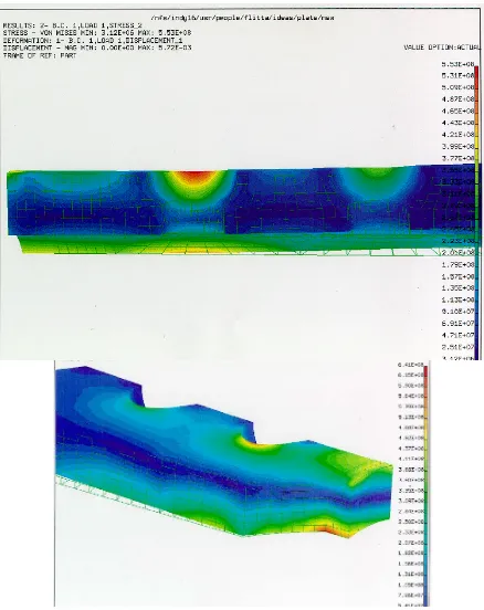
Finite element models of the two designs symmetric about the longitudinal mid-plane including the innermost screw hole and the adjacent regions up to the next hole position were constructed and shown in Figures 5 and 6. These show the Von Mises stress distribution for both fracture plate designs under the two specified loading conditions. Von Mises stress is used as a fatigue criterion, since fatigue is the expected mode of failure. It should be noted that in all the models considered no portion of the model appeared to be yielding. Utilising Von Mises yield criterion showed that finite element analyses were within the elastic range. If loads were increased due to dynamic effects, then analyses including plasticity may be appropriate.
When pure three point bending is specified the two models react differently, the maximum stress occurs at different locations. For straight edge model the stress levels tend to be lower with the innermost screw holes carrying increased stresses, with the highest stress of 553 MPa. For the waisted edge model (the control case) the highest stress concentration occurs around the middle of the span with the stress of 641 MPa. This is an increase of 16% over the
straight edge model. However the next highest stress in the waisted edge design is around the inner screw holes with a value of 225 MPa. A similar trend was also present for torsional load case. Thus the inner screw hole regions are the most likely areas for plate failure. Preliminary destructive tests on the fracture plates have confirmed these findings.
Therefore the waisted profile can be optimised further by increasing the radius to reduce the local stress in the mid span to match the stress around the inner holes. It is believed that once the waisted edge design is optimised it will eventually prove more satisfactory for general use. Although it does not appear to be as strong as the straight edge plate but as it is less rigid it can result in a better fracture fixation.
4.0 Conclusions
It is important to tailor make the stress/ stiffness distribution of fracture plates. The highest stresses occur in the inner screw hole regions. To optimise the stress/ stiffness the plate can be waisted to yield a more uniform stress distribution.
References
1. Huang TL, Huang CK, Yu JK, Chiu FY, Liu HT, Liu CL, Chen TH “Operative treatment of intra-articular distal radius fractures using the small AO external fixation device”, J Chin Med Assoc, Oct 2005, 68 (10):474-8.
Figure 1 Forearm fractures and fracture fixation plates
Figure 3 Load boundary conditions applied on a quarter fracture plate model showing the effect of screw and the bone pressure on the
fracture plate.
3. Anderson, LD “Compression Plate fixation and the effects of different type of internal fixation on structure healing” , J Bone Joint Surg 47A, 1965, p.191-208.
4. Terjesen,T and Apalset, K “The influence of different Degrees of Stiffness of Fixation Plates on Experimental Bone Healing”, J Ortho. Res., 6, 293-299,1988.
5. Terjesen,T ”Bone Healing after metal Plate Fixation and External Fixation” Acta Orthop Scand 55,69-77, 1984.
6. Inoue, N and Hirasawa Y "Composite materials in Bio-medical engineering" , J. Materiaux & Techniques, 1994, 82(4-5) p.23-26.
Figure 2 Part of the waisted fracture plate (a quarter model) showing the mesh density and reduction in the plate breadth.
Figure 4Improved design of the hole
[image:8.595.71.323.282.516.2]
Figure 6 Von Mises stress distribution on straight edge and waisted fracture plate models
loaded in torsion
7. Tonino AJ, Davidson CL, Klopper PJ, Linclau LA. “Protection from stress in bone and its effects: experiments with stainless steel and plastic plates in dogs”, J. Bone Joint Surg 1984; 58-B: 1107-113.
8. Claes L, Palme U, Kirschbaum U. “Biomechanics: Principles and applications”, Huiske, R, Van Campen, D and De Wijn, J (eds). Martinus Nijhoff Publisher, The Hague, 1982; 325-30.
9. Grijpma DW, Nihenhuis AJ, van Wijk PGT, Pennings AJ. “High impact strength as polymerized PLLA” Polymer bulletin 1992; 29: 571-8.
10.Uhthoff KH, Dubuc FL. “Bone structure changes in the dog under rigid internal fixation” Clin Orthop 1971; 81: 165-70.
11.Woo SL, Akeson WH, Coutts RD, Rutherford L, Doty D, Jemmott GF, Amiel D. “A comparison of cortical bone atrophy secondary to fixation with plates of larger differences in bending stiffness”, J Bone Joint Surg 1976; 58-A: 190-5.
12.Tayton K, Johnson-Nurs C, McKibbin B, Bradley J, Hastings G. “The use of semi-rigid carbon-fibre reinforced plates for fixation of human factors”, J Bone joint Surg 1982; 64-B: 105- 11.
stainless steel plates for the internal fixation of fractures”, J bone Joint Surg 1981; 63-B: 427-34.
14.Woo SL, Lothringer KS, Akeson WH, Coutts RD,Woo YK, Simon BR, Gomes MA. “Less rigid internal fixation plates: historical perspectives and new concepts”, J Orthop Res 1984; 1:431-9.
15.Manninen MJ, Paivarinta U, Taurio R, Tormala P, Suuronen R, Raiha J, Rokkanen P, Patiala H. Polylactide “screws in the fixation of olecranon osteotomies: a mechanical study in sheep”, Acta Orthop Scand 1992; 63: 437-42.
16.Suuronen R, Pohjonen T, Tech L, Vasenius J, Vainionpaa S. “Comparison of absorbable self-reinforced multilayer poly-l-lactide and metallic plates for the fixation of mandibular body osteotomies”, J Oral Maxillofac Surg 1992; 50: 255-62.
17.Cochram, GVB, Palmier, RV and Re. Zickel. "Aramid-Epoxy composite internal fixation plates- A pilot study", J. Clini. Biomechanic. 1994, 9(5), p.315-322
18.Hofman GO "Biodegradable implant in Orthopaedic surgery" J. Clin. Mater., UK 1992, 10(1-2), p. 75-80.
19.Tayton K., Philips G. and Ralis Z."Long Term Effect of Carbon Fibre on Soft Tissues", J of Bone and Joint Surgery, 1982, 64b, p.112.
20.Williams D.F., McNamara A. and Turner R.M. “Potential of PEEK and CFRPEEK in medical application” J. Materials Sciences Letters, 1987, 6, p.188-190
21.Farling G.M.andGreer, K."An improved bearing materials for joint replacement
prosthesis: Carbon fibre reinforced UHMWPE" , GW Hastings and DF Williams (Eds) Mechanical Properties of Biomaterials, John Wiley & Sons Ltd, 1980, p.53-64.
22.Claes L."The Mechanical and Morphological Properties of Bone Beneath Internal Fixation Plates of Differing Rigidity” J. Orthopaedic Research, 1989, 17(2), p.170-177.
23.Foux A, Yeadon A, Uhthoff HK. “Improved fracture healing with less rigid plate: a biomechanical study in dogs”, Clin Orthop Rel Res. 1995.
24.Yeadon A, Foux A, Uhthoff HK, Russel D. “Influence of axially flexible plates on bone healing: a biomechanical study in canine femora”, Proc Can Med & Biol Eng Soc Meeting 1994; 34-5.
25.Steinmann, SC “Characteristics of an Ideal Implant Material for Stable Fixation”, in Current Concepts of internal Fixation of Fractures, UK, Uhthoff (Ed), Springer, Verlag, New York, 93-99, 1980.
26.Szivek, JA and Yapp, RA “A Testing Technique allowing Cyclic Application of Axial, Bending, and Torque Loads to Fracture Plates to Examine Screw loosening”, J Biomed Mater Res, Appl Biomat, 23(A1), 105-116, 1989.
27.Uhthoff, HK “Mechanical factors influencing the holding power of screws in compact bone” J Bone Joint Surg, 55B, 633-639, 1973.
bone screws”, Clin Orthop. Res, 157, 279-286, 1981.
29.Zand, MS et al “Fatigue failure of cortical bone screws”, 16, 305-31, 1983. 30.Hidaka, S and Gustilo RB “Fracture of bones of the forearm after plate removal”, J Bone Joint Surg AM 66, 1241-1243, 1984.
31.Rumball, K and Finnegan, M “Refractures after forearm plate removal” J Ortho Trauma 4, 124-129, 1990.
32. Cheal EJ, Hayes WC, White AA, Perren SM. “Stress analysis of compression plate fixation and its effects on long bone remodeling”, J. Biomesh 1985; 18: 141-50.
33.Beaupre GS, Carter DR, Orr TE, Csonggradi J. “The importance of friction interfaces in mathematical models of plated long-bones”, Trans 33rd Orthop Res Soc Meeting 1986: 476.
34.Nazre A, Lin S. “Clinical and Laboratory Performance of Bone Plates”, STP 1217. Harvey, J.P. and Games, F. (eds), ASTM Philadelphia. 1994, 53-64.
35.Cohen B, Hoeltzel DA. “Design optimization of an aramid fibre composite internal fixation plate”, Advances in Bioengineering, ASME 1992: 23-5.