A Brief Survey on Traffic Protection Mechanism for Efficient Rerouting
in MPLS
Sandhya T. J.
1A. Venugopal
2 1Research Scholar
2Assistant Professor
1,2Department of Computer Science & Engineering
1,2Sree Narayana Guru College, Coimbatore 641105, India
Abstract— When there is a failure in any system or link then the network must be capable enough to maintain all the actions and tasks that are to be implemented. This category of perfect network is said to be network pliability. The network pliability is the concept of automatic network recovery from various failures by rerouting the traffic from any sort of traffic from the failure and they can be converted back to the vigorous part of another network. The rerouting technique is quicker and the service intervening caused by the failure of the node is imperceptible to other network and the process tends to be very small. The fast rerouting is the procedure for path calculation and it is performed through tunnel to create vast routing area before the occurrence of failure. At present, Multi-protocol Label Switching (MPLS) turns out to be the innovative method for Internet service providers. MPLS is comprised of various attributes like traffic engineering performance and initiating quality of service. Multiprotocol Label Switching (MPLS) fast reroute (FRR) is based on one-to-one or many-one-to-one backup methods. The Fast Reroute technique is the steganographic method for delineating the different MPLS traffic protection mechanisms. In this survey various techniques are projected for the fast rerouting in MPLS networks.
Key words: Reroute, MPLS, FRR, Path Calculation
I. INTRODUCTION
The traffic rerouting is the concept of placing the traffic parameter in the topology of the network. Hence the routing methods are introduced to control the traffic in the network. This type of routing methods that allows assigning the network competence and it may be more or less competent for the weights. The routing option has a direct intuition on the survival and location of congestion within the network [1]. The service estimation can be minimized by the congestion level i.e. rate of increasing the interruption and call blocking.
Routing techniques within the IP network could motivate some restrictions on the given pathway selection associated to various path selection algorithms. The consequence occurs iteratively in the case of IP networks. During this problem, the routing takes the simple fast routing methods by computing the shortest path which has less control compared to the path routing. This gives rise to the usage of sub optimality of the resources in the network. Recently, the algorithms are found to expand the power of routing and also to perform network optimization between the MPLS. But these methods have introduced few of the network management problems.
The routing protocol called “IP protocol” that carries the transfer load diagonally in the path of exact objective. The intention of next hop must be renowned in the nodes among the feasible favorable paths for the network traffic duration.
The administrative area is engaged with the routing table at every node and it has the dependability of some of the routing protocols like Interior Gateway routing Protocol (IGP) or this method can also be developed in concurrence throughout the Exterior Gateway routing Protocol (EGP). Routing protocols involves the method of IP whereas the primary information protocol is used to exchange the information dynamically among unique nodes for proper path routing. The transport layer is held in routing protocols to hold reliable transmit of their communication management [16]. The information about the system changes and the control information are reinstated among the routing method sequentially at every intermediary node that is equipped in a harmonized mode.
The contradictory network information is the major drives for unstructured delivery of IP packets to the destination or callous situation to drop the packet. The rationale existing in these hard situations is that extraordinary IP packets dispense a familiar source and destination and this may be located adjacent to curious paths. The position of the network might alter due to the possessions of associated modernized information or breakdown of the location. In these two areas, nodes are related to esteemed boundary and the data are revised in their database tables i.e. not available in the routing table and the information is presented it to other neighbors donating in constructing up a picture of topology of the field [15]. Hence, every node’s fidelity is to have effectual database continuously and the interior IP packet may travel in the perfect method. The announcements regarding the information about topological data have to be restored among the nodes. The methods like Distance Vector Routing Protocols (DVRP) such as RIP (Routing Information Protocol) and EIGRP (Enhanced Interior Gateway Routing Protocol) contains the effectual data and it is restored between the correlated neighbors by promoting the predictable favorable paths available that result in calculating the dispersed route [4].
has a consistent observation topology structure combined together with harmonized LSDB. This associated LSDB is called as the source for computing SPF. The nodes will generate the SPF method and it acts as a source node f the tree and then it computes the arriving cost at atypical nodes by absorbing the leaves in the tree by finding out the Shortest Path Tree (SPT). Previously, the SPT is built at each causal nodes finally live in routing table and it is also accepted as Routing Information Base (RIB). This SPF method is implemented on recent inward Link State Advertisement (LSA). A disadvantage of SPF computation is that the exemption procedure gets improved by handling more number of nodes linked in the process of routing [7]. The computation load can be overcome by generalizing the LSA’s inside the network section. An LSRP range is segregated into exceptional areas and most of the LSA’s are restricted inside the mentioned region. By elucidating the fundamental usefulness of MPLS functionality, difficulties of traditional IP onward techniques must be outlined:
Routing protocols are employed on all process to assign the fundamentals of routing.
The routers always convey the packets on the destination address and the segregation is policy-based routing (PBR) that evade the visit of destination routing. Routing lookups are implemented on every router and
the router generates the self-determining verdict in the network during the packet forwarding.
The assistance of MPLS minimizes the routing identification and convert the ahead’s method and eliminates the need to implement the exact routing protocol in all the methods.
II. RELATED WORK
Many authors are working on MPLS and the concept of modified MPLS is suggested and it is better compared to old MPLS. Gaeil Ahn et al. in 2001 introduced the effectual rerouting mechanism to categorize the LSP adjacent to the least-cost revival route of all possible discretionary routes that can be recognized on the basis of its working that is measured through the technique of uphill LSR that has observed a disintegrate [5]. The projected method can maximize the resource utilization, ascertaining the path recovery which is relatively fast; assist all the types of failures like link, node failures on the working and the recovery path and the synchronized faults. In this method, path recovery is established. The first procedure called Candidate-PMLs is utilized for path recovery. The second procedure called Least-Cost Recovery-Path algorithm is used to compute the least-cost path of all probable optional paths among their own and other few Candidate-PML. The outputs depict the better outcomes in analyzing the path and node failures and the resource utilization methods are efficient than existing procedures even though it is deficient in synchronized faults. Yimin Qiu et al. in 2009 proposed the algorithms for recovery and discussed the NS-2 tool for MPLS. When the failure occurs in any path or the link, switching is performed for the pre-established path recovery and it is appended with the recent path recovery model. Hence, this method can assure the immovability and reliable transmission. This work is accumulated with TCL programs by NS-2 tool that performs
the feasibility and weight analysis of the recovery model for the less delay.
Eli V. Olinick et al. in 2011 gave the overview of the IMFPAM and it has the feature of ILP to get resolved by identifying the increased amount of throughput by executing one increment and the increased amount of k demands are incremented by rerouting. The rate of throughput can be enhanced by improving the k value till the required throughput is attained [16].
Aubin Jarry et al. in 2013 have introduced the algorithmic medium for the original path calculation by providing back up facility to enhance the quality of service feature under the criteria’s of a single or multiple link failures that comes under same Shared Risk Link Group (SRLG). This type of difficulty can be resolved by calculating the distance recovery for the failure link and this may become harder for multiple paths.
The remaining sections are described as follows: section 3 describes the MPLS traffic engineering, section 4 describes the fast reroute operation, section 5 describes the reroute schemes, section 6 describes the conclusion and section 7 gives the references.
III. MPLS TRAFFIC ENGINEERING (TE)– FAST REROUTE
LINK AND NODE PROTECTION
A. Fast Reroute
Fast Reroute (FRR) is a method for defending MPLS TE LSPs failures from link and node by locally performing the revamping the LSPs at the failure point, permitting the information to prolong to flow, whereas the new feature of end to end LSP’s are evolved by the head end routers to reinstate them [12]. The secluded LSPs are revamped by FRR by rerouting and by passing them over the failed links or backup tunnels that bypass.
B. Link Protection
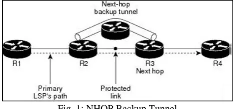
[image:2.595.311.545.581.690.2]The single link of the LSP’s path is evaded by backup tunnels that afford link fortification. The LSPs can be fortified when the path failure occurs along the path by performing rerouting the traffic occurred in one network to the next hop by evading the link failure. This structure discards the next hop of the LSP’s away from the failure and it is called as next-hop (NHOP) backup tunnels [2]. The figure 1 depicts the NHOP backup tunnel.
Fig. 1: NHOP Backup Tunnel
C. Node Protection
subsequent the next-hop node of the LSP paths by evading the next-hop node. When there is a failure in the node and the path, the LSPs are protected by facilitating the upstream of the node failure to redirect the LSPs and traffic surrounding the failure node to the next-next hop is also enabled [13]. An NNHOP backup tunnel is the basic feature for link failure protection because the link and node failure are evaded and it is depicted in figure 2.
When there is an alteration in LSP that is used by the backup tunnel and hence it is not taken for the backup tunnel and the LSP’s are worn out. The changes are listed below:
Backup tunnel’s bandwidth is minimized.
The primary part of the LSP is mismatched to the modified category of the backup tunnel.
[image:3.595.310.546.160.346.2] The alterations in the primary part of the LSP disables the FRR i.e. the rerouting rule is not applied in MPLS traffic engineering.
Fig. 2: NNHOP Backup Tunnel
D. Bandwidth Protection
The backup bandwidth characteristic is applied for rerouting the LSPs by providing them with the bandwidth protection and the protection mechanism can be given by NHOP and NNHOP backup tunnels. The backup bandwidth is correlated with NHOP or NNHOP backup tunnels. The quantity of the backup bandwidth is informed to the router by protecting a specific backup tunnel. The LSPs are associated with the backup tunnels by routers when there is an adequate amount if backup bandwidth then the LSP can make use of the backup tunnel by backup protection [4]. The LSPs are chosen by the router based on the category of backup tunnels to afford high level of bandwidth protection. This can be achieved by the usage of router i.e. it finds the accurate path to associate LSPs to backup tunnels to increase the amount of protected LSPs.
IV. FAST REROUTE OPERATION
The TE is the tunnel placed between the two devices R1 and R2 by affording the quickest reroute in protecting the link where the traffic is held in TE. There is a mid-point link and it is navigated between devices R2 and R3. The primary part of the tunnel is the TE tunnel from R1 to R9 defined by labels 37, 14, and Pop. The backup tunnel is generated to safeguard the link from R2–R3 where it travels from the pathway R6 and R7. The label names like 17, 22 and pop are defined by the backup tunnel [10]. The node R2 have link within it and when it notices that the R3 is not available it just transmit the traffic ordained for R3 by the means of backup tunnel. This
can be attained after performing the usual swap operation by pushing the 17th label to packets predestined to the link R3
and label 37 is replaced with the label 14. The label 17 is pushed into the packets and it is transmitted next to the backup tunnel and traffic is routed in the unsuccessful link. The packet rerouting decision is executed by R2 from the primary tunnel to the backup tunnel based on the link failure detection.
Fig. 3: Backup Tunnels – Fast Reroute
A. Fast Reroute Activation
The two approaches are used by the routers to change LSPs to the backup tunnels:
Notification regarding interface down
Notification regarding RSVP (response from the invited person or people) Hello neighbor
The failure occurring in the link or the neighbor node of the router makes the router to identify this type of failure by the first notification called interface down. The Global State Routing (GSR) Packet over the interface SONET warning is quicker. When the interface seems to be down and it is watched by the router by changing the LPSs which is out of the interface into the individual backup tunnels [8]. The FRR is triggered by RSVP Hellos. The information is sent sporadically to the neighboring routers by configuring the RSVP Hellos on the interface. Hello tells that the neighbor is down when the correct response has not yet established. This feature makes the LSP interface to change to their individual backup tunnels.
B. Backup Tunnels Terminating at Different Destinations
[image:3.595.47.289.245.444.2]Fig. 4: Backup Tunnels Terminating at Different Destinations
In this diagram, R1 has single interface and it entails numerous backup tunnels. LSPs navigate the subsequent routes:
R1, R2, R3 R1, R2, R4
When the R2 fails, the protection can be afforded and the two types of NNHOP backup tunnels are needed: one concluding at R3 and one concluding at R4.
C. Backup Tunnels Terminating at Same Destination The figure 5 describes the method of terminating the backup tunnels at the identical location and hence it is utilized for the purpose of redundancy and balancing the load. This purpose is employed for both the backup tunnels NHOP and NNHOP.
Fig. 5: Backup Tunnels Termination at Same Location There are three routers named as R1, R2, and R3. T1 and T2 are the two NNHOP backup tunnels at the router R1 and that travel from the route R1 to R3 without going across R2. When the redundancy concept exists, if the link from R1 to R2 or even the R2 fails then the backup tunnel can be employed [14]. If any one of the backup tunnel fails then another tunnel can be used. The LSPs are allocated to backup tunnels by establishing the LSPs before the occurrence of failure. Both the type of tunnels can be utilized with the help of load balancing when the backup tunnel has adequate bandwidth to restore all LSPs. Some of the LSPs may utilize backup tunnel, and few may use the other types of backup tunnel. The routers choose the accurate way to apply LSPs into the backup tunnels.
V. REROUTE SCHEMES
[image:4.595.299.549.339.526.2]Gaeil Ahn et al. suggested the method that contains the features of both rerouting model and local repairing. Hence the type of path recovery is planned throughout the upstream LSR because the fault condition is on the equipped path. While reconstructing the failure, the illustrated path recovery is disentangled. Figure 6 shows the restoration functional method briefly. A path recovery path is arranged as follows: a) the least cost path of the entire probable optional paths among them and every candidate-PML (Path Merge LSR) are computed by failure identification of the upstream LSR (Label Switched Router). Then, the upstream LSR will determine the least cost path of the PML and the precise path up to the PML. b) A path recovery is found along the computed precise path from the upstream LSR to the PML. In this type of path recovery setup, the precise path is embedded inside the ER (Explicit Route) of MPLS signaling message (e.g., CR-LDP, RSVP). The LSPID (LSP Identifier) of the operational LSP is utilized as an ER hop for the intention of merging the already available operational LSP and its recent recovery LSP to be launched [9]. The priority holding of the operational route may be employed as the precedence setup of the path recovery.
Fig. 6: Rerouting Scheme
The traffic prevailing in the operational path gets converted into recovery path once the recovery path is launched. c) If the path recovery fails in the setup phase then move to (a).
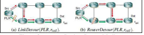
[image:4.595.52.283.428.581.2]Fig. 6: One to one Backup Detour Medium
The occurrence of failure makes the process to be intricate for the router to identify whether the contiguous router or the failure of the associating link. It is to be assumed that, the failure of the router is probable and the final link of the primary route fails then the link detour can be utilized by excluding the router detour [6].
VI. CONCLUSION
MPLS has established as an encouraging procedure that will improve the scalability of the routing and endorsement and deliver facilities for accurate network supplying. It de-couples upholder from routing and accepts numerous rules that grasp restricted of necessitate alters to the fundamental ahead’s criteria. The MPLS promptness try is still in a moderately premature stage, and there are a more number of routine concerns that require being indomitable earlier than the standard is absolute. The survey paper aims to provide Multi-Protocol Label Switching where the method that represents the data from one end of the information node to the other on computed short path than long network that focus to highly awarding telecommunications association with high scalability to convey IP services. The concept of traffic engineering is performed by IP or ATM based on the protocol in MPLS.
REFERENCES
[1] Ben-Ameur, W. A. L. I. D., et al. "Routing strategies for IP networks." Telektronikk 97.2/3: 145-158, 2001. [2] Awduche, Daniel, et al. "A framework for Internet traffic
engineering." Network Working Group, Internet Draft (work in progress), http://search. ietf. org/internet-drafts/draft-ietf-tewg-framework-02.Txt, 2000.
[3] Ravindra Kumar Gupta, Arvind Kumar Singh, Pankaj Singh, Omjeet Singh, “Analyzing Multi-Protocol Label Switching Network”, Volume 3, Issue 6, June 2013. [4] Foo, Jack. "A survey of service restoration techniques in
MPLS networks." Proc. of Australian
Telecommunications, Networks and Applications Conference, 2003.
[5] Ahn, Gaeil, and Woojik Chun. "Design and implementation of MPLS network simulator supporting LDP and CR-LDP." Proceedings. IEEE International Conference on. IEEE, 2000.
[6] Kaur .G, Kumar .D, “MPLS Technology on IP Backbone Network”, International Journal of Computer Applications (0975-8887), 2010.
[7] Ravindra Kumar Singh, Narendra S. Chaudhari, Kanak Saxena, “Load Balancing in IP/MPLS Networks: A Survey”, Communications and Network, 2012.
[8] G. Lee and J. Choi, “A Survey of Multipath Routing for Traffic Engineering,” 2002.
[9] Jitendra Joshi, Sonali Gupta, Priti Gupta, Nisha Singh, Manjari Kumari, “Multi-Protocol Label Switching with
Quality of Service in High Speed Computer Network”, Volume 2, Issue 2, March 2013.
[10]Mohammad Yanuar Hariyawan, “Comparison Analysis of Recovery Mechanism at MPLS Network”, Vol.1, No.2, pp. 151~160, December 2011.
[11]Alarcon-Aquino, V., “MPLS/IP analysis and simulation for the implementation of path restoration schemes”, WSEAS Transactions on Computers 3.6: 1911-1916, 2004.
[12]Nortel Networks, MPLS – An introduction to Multi-protocol Label switching, Nortel Networks mkt. publications, April 2001.
[13]Liwen He, SM IEEE, Paul. Botham, “Pure MPLS Technology”, © 2008 IEEE.
[14]Hundessa, Lemma, and Jordi Domingo-Pascual. "Reliable and fast rerouting mechanism for a protected label switched path." Global Telecommunications Conference, 2002. GLOBECOM'02. IEEE. Vol. 2. IEEE, 2002.
[15]R.N.Pise et. al., “Packet Forwarding with Multiprotocol Label Switching” World Academy of Science, Engineering and Technology 12 2007.