Technology (IJRASET)
Comparison of Shear Wall and Bracing in RCC
Framed Structures
Patil S. P.1, Desai R. M.2, Khurd V. G.3 Sanjay Ghodawat Group of Institutions, Atigare.
Abstract— In past few years considerable emphasis has been given on performance based design for earthquake resistant structure. Therefore to increases the ductility of the structure a shear wall or a bracing system is introduced in a moment resisting frame. A shear wall and a bracing system in a RCC framed structure is a wall or system which is designed to resist shear, the lateral force due to earthquake or wind and to control the deflection and to increases the ductility demand. In this paper a comparison of shear wall and bracing in rcc framed structure with different locations is studied and results are presented.
Keywords—RCC framed structure, shear wall, bracing system, earthquake force, gravity load.
I. INTRODUCTION
To resist the lateral load due to earthquake and wind to increase stiffness of hise rise building a shear wall or bracing in place of infill wall is introduced. To resist the lateral load due to earthquake and wind to increase stiffness of hise rise building a shear wall or bracing in place of infill wall is introduced.The term shear wall is actually a misnomer as far as high rise building are concerned, Since a slender shear wall when subjected to lateral forces has predominantly moment deflections and only very insignificant shear distributions. The shear wall accepts a shear of the lateral load proportional to its stiffness. Although the major shear walls are usually in the transverse direction of the building, stability in the longitudinal direction is normally provided by staircase shafts or some longitudinal shear wall The great majority of multistoried buildings today are, in fact, shear wall-frame structures, sin Elevator shafts ,stair wells , and central core units of tall buildings are mostly treated as shear wall, Frame structures depend primarily on the rigidity of member connections for their resistance to lateral forces, and they tend to be uneconomical beyond 5 to 6 stories. To improve the rigidity and economy, shear wall are introduced in building exceeding 5 to 6 stories in height.
The term shear wall-frame structure is used here to denote any combination of frames and shear walls. The shear wall can have any plan shape and may be linear, angular, rectangular or circular in plan.
The common assumption to neglect the frame and assume that all the lateral load is resisted by shear walls may not always be conservative,Consideration of shear wall – frame interaction leads to a more economical design.
Since the shear wall moments are reduced less reinforcing is needed as the frames takes over some of the lateral load movement .in most cases the frames can accept the additional moment due to lateral loads within the 33 % of increase in allowable stresses, except for the top stories of the frame. Which often require additional reinforcing .Shear walls are efficiently utilized if they are distributed about the plan so that they carry their proportional shear of the vertical load, rather than having them function mainly as lateral load resisting element. This condition may, however, conflict with the desirability of locating the principal lateral load resisting elements along or near the periphery of a building.
The main function of a shear wall for the type of structure being considered here is to increase the rigidity for lateral load resistance. Shear walls also resist vertical load, and the difference between a column and shear wall may not always be obvious. The distinguishing features are the much higher moment of inertia of the shear wall than a column and the width of shear wall, which is not negligible in comparison with the span of adjacent beam. The moment of inertia of shear wall would normally be at least 50 times greater than that of a column, and a shear wall would be at least 5 ft. wide.
The introduction of deep vertical element (shear wall) represents a structurally efficient solution to the problem of stiffening a frame system. The frame deflects predominantly in a shear mode. While the shear wall deflects predominantly in a bending mode.
Technology (IJRASET)
resisting a portion of the exterior loads. In the distinctive feature of increasing the stiffness through a set of internal forces lies the great advantage of shear wall – frame interactive systems.
Steel bracing is a highly efficient and economical method of resisting horizontal forces in a frame structure. Bracing has been used to stabilize laterally the majority of the world’s tallest building structures as well as one of the major retrofit measures. Bracing is efficient because the diagonals work in axial stress and therefore call for minimum member sizes in providing stiffness and strength against horizontal shear. A number of researchers have investigated various techniques such as infilling walls, adding walls to existing columns, encasing columns, and adding steel bracing to improve the strength and/or ductility of existing buildings. A bracing system improves the seismic performance of the frame by increasing its lateral stiffness and capacity. Through the addition of the bracing system, load could be transferred out of the frame and into the braces, bypassing the weak columns while increasing strength. Steel-braced frames are efficient structural systems for buildings subjected to seismic or wind lateral loadings. Therefore, the use of steel-bracing systems for retrofitting reinforced-concrete frames with inadequate lateral resistance is attractive.
II. PROBLEM
A 15- storied reinforced concrete building with shear wall ,without shear wall and with different types of bracing in zone V has been considered for the illustration .The main emphasis in this chapter is on calculation of base shear, frequency, period and displacement for different story , and comparing this with shear wall and bracing.
A. Building description
Analyze a 15- storied RC building as shown in fig. The live load on all the floors is 2KN/m2 and soil below the building is hard. The site lies in zone V. All the beams are of size 40 x 50 cm and slabs are 15 cm thick. The sizes of columns are 60 x 60 cm in all the story and the wall around is 12 cm thick. ( SP : 22- 1982 )
Analysis using response spectrum method .Using the software frequency, period, mode participation factor, base shear, displacement is calculatedand presented in tabular format. Results are shown in tables for different location of shear wall and bracing. also for different type of bracing system.
Fig 1 – PLAN Fig2 - 3 D MODEL AND ELEVATION
B. Load calculation
Consider only one middle frame of building to calculate the lump weight.
1) Dead Load
Joint load
Weight of brickwork – 20 x 7.5 x 0.12 x 3 = 54 kN Weight of beams – 25 x 7.5 x 0.40 x 0.50 = 37.5 kN Weight of columns – 25 x 3 x 0.60 x 0.60 = 27 kN
Member load
Technology (IJRASET)
Weight of slabs – 25 x 1.0 x 7.5 x 0.15= 28.125 kN/m Live/ imposed load– 7.5 kN/m
Weight of brickwork – 20 x 1.0 x 0.12 x 3 = 7.2 kN/m Live/ imposed load– 7.5 kN/m
Weight of beams – 25 x 7.5 x 0.40 x 0.50 = 37.5 kN Weight of columns – 25 x 3 x 0.60 x 0.60 = 27 kN Weight of brickwork – 20 x 7.5 x 0.12 x 3 = 54 kN
2D frame shear wall at first bay diagonal bracing at first bay
THE FLOOR WISE DISPLACEMENT IN MM
STEEL DIGONAL(D) BRACING AT FIRST BAY
FLOOR↓ FRAME SHEAR
WALL
BRACING D D ISMB500
BRACING D D ISMB600
BRACING D D ISWB600A
base shear (kN) 522.1 792.25 693.75 716.14 726.34
1 1.46 0.375 0.839 0.711 0.65
2 1.459 0.388 0.85 0.724 0.665
3 2.978 0.954 1.859 1.637 1.532
4 4.476 1.649 2.921 2.62 2.478
5 5.93 2.432 4.004 3.638 3.466
6 7.33 3.271 5.086 4.667 4.471
7 8.672 4.141 6.154 5.694 5.479
8 9.954 5.025 7.2 6.708 6.478
9 11.174 5.909 8.221 7.702 7.461
10 12.328 6.783 9.211 8.673 8.423
11 13.409 7.637 10.166 9.612 9.356
12 14.407 8.462 11.078 10.513 10.252
13 15.309 9.252 11.933 11.363 11.1
14 16.098 10 12.718 12.15 11.888
15 16.754 10.701 13.417 12.86 12.603
Technology (IJRASET)
STEE V-TYPE BRACING AT FIRST BAY
FLOOR↓ FRAME SHEAR
WALL
BRACING
V D
ISMB500
BRACING V
D ISMB600
BRACING V
D ISWB600A
Base Shear 522.1 792.25 752.32 773.54 782.74
1 1.46 0.375 2.111 2.17 2.196
2 1.459 0.388 2.016 2.067 2.089
3 2.978 0.954 2.867 2.849 2.842
4 4.476 1.649 3.69 3.606 3.571
5 5.93 2.432 4.555 4.415 4.356
6 7.33 3.271 5.448 5.261 5.183
7 8.672 4.141 6.357 6.132 6.038
8 9.954 5.025 7.272 7.015 6.908
9 11.174 5.909 8.815 7.903 7.785
10 12.328 6.783 9.09 8.786 8.659
11 13.409 7.637 9.977 9.657 9.522
12 14.407 8.462 10.838 10.506 10.366
13 15.309 9.252 11.664 11.323 11.18
14 16.098 10 12.444 12.102 11.958
15 16.754 10.701 13.17 12.835 12.693
16 17.258 11.327 13.82 13.499 13.363
STEEL X-TYPE BRACING AT FIRST BAY
FLOOR↓ FRAME SHEAR
WALL
BR X
D ISMB500
BR X
D ISMB600
BR X D ISWB600A
Base Shear 522.1 792.25 639.74 655.15 660.88
1 1.46 0.375 0.548 0.453 0.41
2 1.459 0.388 0.556 0.463 0.421
3 2.978 0.954 1.234 1.061 0.984
4 4.476 1.649 1.996 1.757 1.651
5 5.93 2.432 2.813 2.52 2.391
6 7.33 3.271 3.664 3.328 3.18
7 8.672 4.141 4.532 4.161 3.998
8 9.954 5.025 5.404 5.007 4.832
9 11.174 5.909 6.272 5.853 5.67
10 12.328 6.783 7.125 6.691 6.501
11 13.409 7.637 7.958 7.512 7.316
12 14.407 8.462 8.76 8.307 8.108
13 15.309 9.252 9.523 9.068 8.869
14 16.098 10 10.24 9.789 9.592
15 16.754 10.701 10.901 10.462 10.27
Technology (IJRASET)
FRAME SHEAR
WALL BR V D ISWB600A
BASE SHEAR 522.1 792.25 782.74
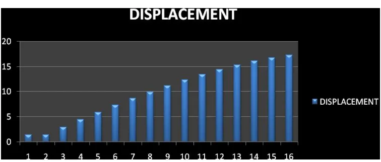
[image:6.612.127.505.174.335.2]MAX. DISPLACEMENT 17.258 11.327 13.363
FIG. - GRAPH- DISPLACEMENT FOR EACH STORY
GRAPH- DISPLACEMENT FOR SHEAR WALL AND DIFFERENT TYPES OF BRACING IN FIRST BAY
SHEAR WALL AT MIDDLE BAY
Technology (IJRASET)
FLOOR↓ FRAME SHEAR
WALL
BR D
DISMB500
BR D
D ISMB600
BR D D ISWB600A
Base Shear 522.1 824.5 710.94 738.8 751.93
1 1.46 0.373 0.965 0.86 0.81
2 1.459 0.376 0.862 0.74 0.681
3 2.978 0.923 1.873 1.656 1.554
4 4.476 1.583 2.915 2.618 2.477
5 5.93 2.317 3.966 3.598 3.425
6 7.33 3.1 5.009 4.582 4.382
7 8.672 3.912 6.037 5.56 5.337
8 9.954 4.742 7.044 6.526 6.284
9 11.174 5.578 8.028 7.476 7.219
10 12.328 6.413 8.986 8.406 8.136
11 13.409 7.238 9.912 9.31 9.03
12 14.407 8.046 10.799 10.18 9.892
13 15.309 8.827 11.634 11.005 10.713
14 16.098 9.575 12.403 11.771 11.478
15 16.754 10.283 13.09 12.465 12.175
16 17.258 10.944 13.681 13.072 12.792
STEEL V-TYPE BRACING AT MIDDLE BAY
FLOOR↓ FRAME SHEAR
WALL
BR V
D ISMB500
BR V D ISMB600
BR V D ISWB600A
Base Shear 522.1 824.5 790.45 816.88 828.22
1 1.46 0.373 2.195 2.268 2.299
2 1.459 0.376 2.157 2.226 2.256
3 2.978 0.923 2.907 2.896 2.892
4 4.476 1.583 3.666 3.581 3.546
5 5.93 2.317 4.457 4.31 4.249
6 7.33 3.1 5.271 5.07 4.986
7 8.672 3.912 6.1 5.852 5.749
8 9.954 4.742 6.937 6.651 6.532
9 11.174 5.578 7.778 7.46 7.327
10 12.328 6.413 8.616 8.271 8.127
11 13.409 7.238 9.444 9.077 8.925
12 14.407 8.046 10.253 9.871 9.711
13 15.309 8.827 11.033 10.641 10.478
14 16.098 9.575 11.775 11.379 11.215
15 16.754 10.283 12.468 12.078 11.916
Technology (IJRASET)
STEEL X-TYPE BRACING AT MIDDLE BAY
FLOOR↓ FRAME SHEAR
WALL
BR X D
ISMB500
BR X D
ISMB600
BR X
D
ISWB600A
Base Shear 522.1 824.5 792.98 823.66 836.91
1 1.46 0.373 0.652 0.542 0.492
2 1.459 0.376 0.654 0.544 0.495
3 2.978 0.923 1.406 1.2 1.108
4 4.476 1.583 2.219 1.93 1.802
5 5.93 2.317 3.071 2.712 2.552
6 7.33 3.1 3.945 3.526 3.341
7 8.672 3.912 4.83 4.362 4.154
8 9.954 4.742 5.719 5.209 4.984
9 11.174 5.578 6.604 6.06 5.82
10 12.328 6.413 7.48 6.91 6.658
11 13.409 7.238 8.341 7.749 7.488
12 14.407 8.046 9.178 8.571 8.303
13 15.309 8.827 9.981 9.365 9.094
14 16.098 9.575 10.738 10.122 9.851
15 16.754 10.283 11.438 10.832 10.565
16 17.258 10.944 12.072 11.485 11.228
FLOOR↓ FRAME SHEAR
WALL
BR X D
ISMB600
BR V D
ISWB600A
BR X D
ISWB600A
BR V D
ISMB600
BASE SHEAR 522.1 824.5 823.66 828.22 836.91 816.88
MAX.
DISPLACEMET 17.258 10.944 11.485 12.574 11.228 12.728
Technology (IJRASET)
III. CONCLUSIONS
The fifteenth story symmetrical RC frame is extensively studdied for seismic loading
A. When shear wall is provided, displacement and storey drift reduces and storey shear and base shear increases.
B. As thickness and width of shear wall increases, displacement and storey drift reduces and storey shear and base shear increases. C. When shear wall is placed symmetrical and well distributed along the periphery the displacements reduce.
D. The concept of using steel bracing is one of the advantageous concepts which can be used to strengthen or retrofit the existing structurs.
E. Steel bracings can be used as an alternative to the other strenthen or retrofitting techniques available as the total weight on the existing building will not change significantly.
F. The lateral displacement of bulding reduced by the use of X type of bracing system.
G. Steel bracing reduce flexure and shear demand on beams and columns and transfer the lateral loads through axial load mechanism.
REFERENCES [1] Mark fintel , fazlur khan “Handbook of concrete engineering”
[2] Thorburn Kulak and Montgomery “Analysis of steel plate shear wall” Structural Engineering report 1983 [3] Elgaaly and Liu “Analysis of Steel Plate Shear Wall “Journal of Structrual Engineering Nov 1997
[4] Astaneh-Asl “Seismic Behavior and Design of Steel Shear Walls” SEAONC Seminar, November 2001, San Francisco [5] H.Ghaffarzadeh and M.R. Maheri “cyclic tests on the internally braced RC frames “JSEE FALL 2006 Vol.8 no.3/177.
[6] T.D. Bush , E.A. Jones “ Behavior of RC frame strengthened using structural steel bracing “Journal of ASCE Structrual Engineering AUG 2010.
[7] M . A. Youssef , H. Ghaffarzadeh , M. Neheli “Seismic performance of RC frames with concentric internal steel bracing “ Engineering structures 29 (2007)1561-1568 oct 2006.
[8] M. R. maheri & A. Saheri . “Use of steel bracing in reinforced concrete frames.” Engineering structures vol. 19 no.12 oct 1996. [9] A.K.Chopra (2007), “Dynamics of Structure”, Prentice Hall, Englewood cliffs, New Jesey, 2007