1874-1290/12 2012 Bentham Open
Open Access
Proof-of-Concept Experiment of Duty Cycle Division Multiplexing with Bit
Error Rate Analysis
Safuraa Mohd Basir
1, Ghafour Amouzad Mahdiraji
2*, Amin Malekmohammadi
3, Noor Hisyam
Ibrahim
1, Ahmad Fauzi Abas
1, Mohamad Khazani Abdullah
41
Photonics and Fiber Optic Systems Laboratory, Centre of Excellence for Wireless and Photonic Networks, Engineering & Technology Complex, University Putra Malaysia, 43400 Serdang, Malaysia
2
Department of Electrical Engineering, University of Malaya, 50603 Kuala Lumpur, Malaysia
3Department of Electrical and Electronic Engineering, The University of Nottingham, Malaysia Campus, Jalan Broga,
43500 Semenyih, Selangor, Malaysia
4Significant Technologies Sdn. Bhd., 43400 Serdang, Selangor, Malaysia
Abstract: Demultiplexing concept of Duty-Cycle Division Multiplexing (DCDM) technique is tested in the back-to-back connection and after transmission over copper wire and optical fiber. Three different lengths of copper wire are tested with the total loss of 3.3, 6.6, and 9.9 dB respectively. Even though the sampling points and threshold values were not dy-namic, the demultiplexing process for the case of back-to-back, and after transmission over the links with 3.3, and 6.6 dB losses, was successful without experiencing any errors. This can be witnessed when the recovered data is compared against the transmitted bits. However, the errors are recorded in the link with 9.9 dB losses, which was mainly due to the non-optimized sampling points and threshold values. In experiment over 60 km Standard Single Mode Fiber, successful transmission was demonstrated. The receiver sensitivity is calculated off-line by using bit error rate analysis. These results confirm the validity of DCDM demultiplexer structure including the sampling process and the data recovery rules.
Keywords: Optical communication system, multiplexing and demultiplexing, duty–cycle division multiplexing.
1. INTRODUCTION
The demand for high-speed internet increases exponen-tially by year. Multiplexing allows many users to share a transmission medium, thus reducing the total cost and com-plexity. Time Division Multiplexing (TDM) [1-3], Fre-quency Division Multiplexing (FDM) or Orthogonal FDM (OFDM) [4-6], and Code Division Multiplexing (CDM) [7-9] are among the popular alternatives. In optical fiber com-munications, with the introduction of Erbium-Doped Fiber Amplifier (EDFA) [10-13], Wavelength Division Multiplex-ing (WDM) [14-16] technology becomes feasible and emerges as the technology of choice in the telecommunica-tion industry. By using WDM, the utilizatelecommunica-tion of optical fiber capacity is increased [17, 18]. Further efforts were taken to increase the capacity utilization of optical fiber by the intro-duction of Polarization Division Multiplexing (PDM) [14, 15, 17-19], Duobinary (DB) [20-23], Differential Quadrature Phase Shift Keying (DQPSK) [17, 24, 25], and Quadrature Amplitude Modulation (QAM) [14, 15, 26].
Recently, Duty-Cycle Division Multiplexing (DCDM) is proposed as an alternative multiplexing and demultiplexing technique to increase the channel utilization of WDM system
*Address correspondence to this author at the Department of Electrical Engineering, University of Malaya, 50603 Kuala Lumpur, Malaysia; Tel: +60126274711; E-mail: [email protected]
[27-33]. In this multiplexing technique, different return-to-zero (RZ) duty-cycles is signed for differentiate channels. The multiplexed signals in DCDM provide one rising edge transition per symbol, which is located at the beginning of the symbol. In addition, the spectrum of DCDM signal have one impulse per multiplexing user, where one of them with the lower frequency is located at the frequency equal to the symbol rate [27-29]. Due to these properties, DCDM pro-vides a simpler clock recovery process and lets the data re-covery process to be performed at the symbol rate. From theoretical and simulation studies, it has been shown that DCDM has narrower spectral width, thereby, better tolerance to chromatic dispersion in comparison to RZ signal [27, 28]. However, to date, there is no experimental work reported verifying DCDM concept. Therefore, it is the interest of this paper to perform a Proof-of-Concept (PoC) experiment to validate the DCDM working principle with the main focus on demultiplexing and the data recovery. To the best of our knowledge, this is the first time that the concept of DCDM is experimentally tested and reported.
2. EXPERIMENTAL SETUP
seven of them (Case 2 to 8), are considered in this experi-ment. Case 1, which all users sending bit zero, is not consid-ered in this prototype due to the hardware limitation. For this purpose, S1, S2, and S3 have fixed pre-coded bit-streams of 1010101, 0110011 and 0001111, respectively.
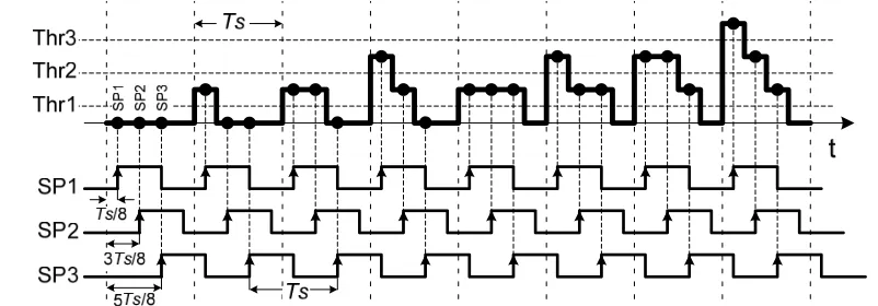
One bit stream per channel from Microcontroller-A will be sent into the Microcontroller-B, whenever the clock is in the high state. Microcontroller-B generates DCDM multi-plexed patterns/symbols (as shown in Fig. (1c)), based on the incoming bits (according to Fig. (1b)). For example, when Microcontroller-B received bit 1 from Channel 1, 2, and 3 (Case 8 in Fig. (1b)), it will generate a step-down shape sig-nal as shown in Case 8 of Fig. (1c). The multiplexed signal is then passed through the Digital-to-Analog Converter (DAC) followed by a current-to-voltage converter. After this stage, DCDM symbol, which each contains 3 bits per symbol (equal to 3 kb/s), are ready for transmission. The base band multiplexed signal is first transmitted over back-to-back connection and then through a copper wire with 3.3, 6.6 and 9.9 dB losses. In these setups, the baseband signals are not modulated onto any carrier. At the receiver side, Microcon-troller-C is designed according to the demultiplexing struc-ture discussed in the reference [30]. In this microcontroller, as illustrated in Fig. (2), three different samplers (SP), SP1, SP2 and SP3, which operate at the frequency equal to the symbol rate (1 kHz), are utilized taking three samples per symbol. The three samplers are designed such a way that the first sampler, (SP1), samples the first slots by a delay of Ts/8 s (or 0.125 ms); the second sampler, (SP2), samples the sec-ond slots with the delay of 3Ts/8 s (0.375 ms); and the third sampler, (SP3), samples the third slots with the delay of 5Ts/8s (or 0.625 ms), from the beginning of the symbol as
shown in Fig. (2), where Ts is the symbol duration. Sample is not taken from the fourth slots, since it is the guard slot without carrying any information. Each sampling point is then compared against three threshold (Thr) values, Thr1, Thr2, and Thr3, as shown in Fig. (2). The DCDM signals are
then recovered by employing the recovery rules reported in the references [27, 28, 30]. Due to the processing time, the recovered signals experienced 1-bit delay (1 ms). The sam-pling points and the threshold values are embedded into Mi-crocontroller-C referring to the fixed bit rate (1 kb/s) and the fixed output voltage signal from Microcontroller-B.
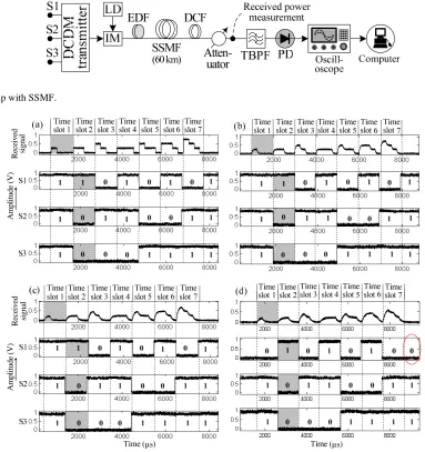
In another experiment as shown in Fig. (3), the multi-plexed signals are externally modulated using an analog In-tensity Modulator (IM) onto an optical carrier, which is gen-erated by a Distributed Feedback (DFB) Laser Diode (LD) oscillating at 1550 nm. The modulated signal is then boosted by employing a short length of Erbium Doped Fiber (EDF). The signal is then transmitted over 60 km standard single mode fiber (SSMF), (with dispersion coefficient of 17 ps/(nm.· km) and attenuation of 0.19 dB/km), followed by three Dispersion Compensation Fiber (DCF) modules with the total attenuation and dispersion of around 8 dB and 1020 ps/nm, respectively. A variable optical attenuator is also added after the DCF modules to control the received power for the purpose of sensitivity measurement. Then the signal is passed through an optical Tunable Band Pass Filter (TBPF) followed by a p-i-n photo diode (PD). In this ex-periment, there is no preamplifier before the optical BPF, due to unavailability of EDF/EDFA. The demodulated sig-nals after the photodetector are captured from the oscillo-scope and analyzed in off-line. Due to unavailability of elec-trical low-pass filter (LPF), the output signal from the
pho-Fig. (1a). Experimental setup for 3-channel DCDM system, (b) eight possible combinations of bits for multiplexing 3 channels, and (c) eight possible DCDM multiplexed patterns.
Fig. (2). Schematic of sampling process using three samplers operating at the symbol rate.
Digital to
ana
lo
g
converter (D
AC)
Current to
vo
ltage
converte
r (LM741
)
Sampl
ing Circuit
Da
ta recove
ry
Microcontroll
er-A
Microcontroll
[image:2.612.156.472.65.186.2] [image:2.612.103.504.219.359.2]todetector is directly used for performance analysis. Bit Er-ror Rate (BER) of the received signal is then estimated using the bit error rate analysis presented in the reference [30].
3. RESULT AND DISCUSSION
Three channels each running at 1 kb/s are multiplexed us-ing DCDM in electrical domain usus-ing microcontroller. The 3 kb/s baseband multiplexed signals are then transmitted over multiple lengths of copper wire without modulating over any carrier. The received signals are then demultiplexed accord-ing to the recovery rules that are embedded into the Micro-controller-C (Fig. 1). DCDM demultiplexer concept and the data recovery rules are first tested in the back-to-back con-nection. As example, Fig. (4a) (the top signal), shows seven patterns of DCDM received signals for the back-to-back connection that is captured from the oscilloscope. The eye diagram in this case is presented in Fig. (5a), which is gener-ated in the off-line. The received signal is then demulti-plexed using the Microcontroller-C with one bit delay and extracted from oscilloscope as shown in Fig. (4a), where the signal S1, S2, and S3 represent the regenerated signals for
the Channel 1, 2, and 3, respectively. In this experiment, as the eye diagram implies, there is no attenuation and delay to affect the transmitted signal. From the received signals, it is observed that all the transmitted signals are recovered back correctly without any error count from the regenerated sig-nals. This result confirms the validity of DCDM demulti-plexer and recovery rules.
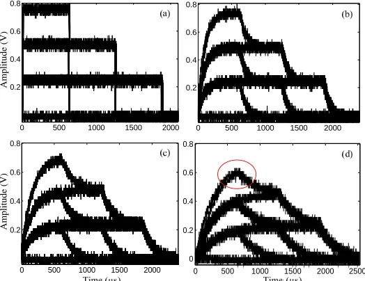
In addition to the back-to-back connection, DCDM sig-nals are transmitted over several meters of copper wire to validate DCDM demultiplexer and recovery rules when the impairments such as attenuation and delay are exist in the medium. In this case, DCDM baseband signals are transmit-ted over 100, 200, and 300 m copper wires with total loss of around 3.3, 6.6., and 9.9 dB, respectively. As example, seven patterns of DCDM received signals for the case of 100, 200, and 300 m copper wire are captured from oscilloscope and presented in top of the Fig. (4b, c), and (d), respectively. The eye diagrams for the case of 100, 200, and 300 m copper wire are shown in Figs. (5b, c), and (d), respectively. As the eye diagrams and the received signals shown, the effect of attenuation and delay become stronger at the higher copper
Fig. (3). Setup with SSMF.
Fig. (4). Examples of received signals and the recovered data captured from oscilloscope for the case of (a) back-to-back connection, (b), (c), and (d) over the link with 3.3, 6.6, and 9.9 dB losses, respectively.
Re
cei
ved
si
g
n
al
Amp
litu
de (
V
)
Re
ce
ive
d
sign
al
Am
plit
ude
(V
[image:3.612.112.495.55.462.2]wire length. The received signals are then demultiplexed and recovered back as example of them for the case of 100, 200, and 300 m are shown in Figs. (4b, c), and (d), respectively. The result from the regenerated signals shows that all the transmitted signals for the case of 100 and 200 m are recov-ered correctly without any errors occurred. However, in the case of 300 m, a fixed error, which is one bit error per every seven symbols (or every 21 bits), is observed for Channel 1 (channel with the shortest duty-cycle), as highlighted by a circle in Fig. (4d). This error is mainly due to the non-optimization of the sampling point and the threshold values. As mentioned earlier, in this experiment, the sampling points and the threshold values are fixed in the Microcontroller–C. This is why, the signal related to the Channel 1 experienced error (out from the threshold (Thr3) value), which is located at the higher amplitude (as highlighted with a circle in Fig. (5d). This problem can be improved by optimizing the sam-pling point and threshold values. Nevertheless, these results validate the concept of DCDM. Even though the signal expe-rienced loss and delay, to certain extent, the original signal can still be recovered.
Another observation from this experiment is the non er-ror propagation within the symbol. This means that even though some part of the received symbols is in error, the data for other channels can still be recovered correctly. One prop-erty of DCDM signals is that any error occurred in the first slot (the slot with the shortest pulse width), will not affect on the other channels. Also, any error occurred on the second slot, will not affect on Channel 3. However, any error oc-curred in the second and third slot will directly affect on Channel 1, and 2, respectively.
In addition to the copper wire, DCDM multiplexed signal is modulated over an optical carrier and transmitted through 60 km SSMF as the setup shown in Fig. (3). As explained earlier, one attenuator is used in the link to change the sys-tem received power. The received signals are then extracted from the oscilloscope and analyzed in off-line for every point of the received power. Fig. (6) shows the BER as a
function of received power for three-channel DCDM system (receiver sensitivity) without preamplifier. Performance of the system is almost linearly reduced by increasing the at-tenuation of the system. In general, performance of Channel 1 (S1), which has the shortest pulse width, is worst that the other channels. On the other hand, performance of Channel 3 (S3), which has the longest duty-cycle, is the best. With ref-erence to BER 10-9, Channel 1, 2, and 3 required received power of around –21.8, –22.5, and –24.5 dBm, respectively. This result is similar to the simulation results reported the in references [28, 30], which the channel with the shortest and the longest pulse width performs as the worst and the best channels, respectively (the exact value differs due to differ-ent bitrate). Performance of the system is expected to be im-proved by employing preamplifier, and electrical LPF to eliminate photodetector noise. In addition, the difference between performance of different channels can be reduced by optimizing the signal level spacing in adjacent levels as reported in the reference [34].
Fig. (5). Eye diagram of DCDM signal for the case of (a) back-to-back connection, (b), (c), and (d) over the link with 3.3, 6.6, and 9.9 dB losses, respectively.
Fig. (6). Receiver sensitivity of 3-channel DCDM system after transmission over 60 km SSMF.
0 500 1000 1500 2000
0.2 0.4 0.6 0.8
0 500 1000 1500 2000
0.2 0.4 0.6 0.8
0 500 1000 1500 2000
0.2 0.4 0.6 0.8
0 500 1000 1500 2000 2500
0 0.2 0.4 0.6 0.8
Amplitud
e (V)
Amplitude (V)
[image:4.612.180.442.61.263.2] [image:4.612.343.547.526.706.2]The proof-of-concept experiment of DCDM has been successfully demonstrated, which shows the feasibility of its demultiplexing concept and the recovery rules. Even though, the system was not in the optimized form, the received signal that experienced channel impairments is successfully recov-ered. One may argue that the bitrate used in this experiment does not reflect the system ability to support high capacity transmission. However, as the objective is only to prove the viability of DCDM concept, it is considered achieved. The success of this technique will open a new research paradigm in optical communication systems history. Transmission of 3-channel DCDM over single wavelength proves that using this technique, WDM channel utilization can be increased by several folds. This technique will become a new alternative to fulfill the future telecommunication network requirement to support high speed operation.
CONFLICT OF INTEREST
None declared.
ACKNOWLEDGEMENTS
This work was supported by the Universiti Putra Malay-sia Research University Grant Scheme.
REFERENCES
[1] S.L. Jansen, R.H. Derksen, C. Schubert, X. Zhou, M. Birk, C.J. Weiske, M. Bohn, D. van den Borne, P.M. Krummrich, M. Moller, F. Horst, B.J. Offrein, H. de Waardt, G.D. Khoe, and A. Kirstadter, "107-Gb/s full-ETDM transmission over field installed fiber using vestigial sideband modulation," In: Optical Fiber Communication and the National Fiber Optic Engineers Conference, 2007.
OFC/NFOEC 2007. Conference on, 2007, pp. 1-3.
[2] E. Lach, K. Schuh, B. Junginger, G. Veith, J. Lutz, and M. Moller, "Challenges for 100 Gbit/s ETDM Transmission and Implementa-tion," In: Optical Fiber Communication and the National Fiber Optic Engineers Conference, 2007. OFC/NFOEC 2007. Confer-ence on, 2007, pp. 1-3.
[3] W. Xiaoxia, A. Bogoni, S.R. Nuccio, O.F. Yilmaz, M. Scaffardi, and A. E. Willner, "High-Speed Optical WDM-to-TDM Conver-sion Using Fiber Nonlinearities," IEEE J. Sel. Top. Quantum Elec-tron., vol. 16, pp. 1441-1447, 2010.
[4] E. Vanin, "Performance evaluation of intensity modulated optical OFDM system with digital baseband distortion," Opt. Express, vol. 19, pp. 4280-4293, 2011.
[5] L. Mehedy, M. Bakaul, and A. Nirmalathas, "Frequency interleav-ing towards spectrally efficient directly detected optical OFDM for next-generation optical access networks," Opt. Express, vol. 18, pp. 23161-23172, 2010.
[6] E. Yamada, A. Sano, H. Masuda, T. Kobayashi, E. Yoshida, Y. Miyamoto, Y. Hibino, K. Ishihara, Y. Takatori, K. Okada, K. Hagimoto, T. Yamada, and H. Yamazaki, "Novel No-Guard-Interval PDM CO-OFDM Transmission in 4.1 Tb/s (50 x 88.8-Gb/s) DWDM Link over 800 km SMF Including 50-GHz Spaced ROADM Nodes," In: Proc. OFC/NFOEC, San Diego, California, 2008, Paper PDP8.
[7] A. Kim, "Photonic CDMA systems with security physical layers,"
IEEE Commun. Lett., vol. 15, pp. 1-3, 2011.
[8] Y.K. Choi, K. Hosoya, C.G. Lee, M. Hanawa, and C.S. Park, "A hybrid WDM/OCDMA ring with a dynamic add/drop function based on Fourier code for local area networks," Opt. Express., vol. 19, pp. 6243-6252, 2011.
[9] H. Beyranvand and J.A. Salehi, "Multirate and multi-quality-of-service passive optical network based on hybrid WDM/OCDM sys-tem," IEEE Commun. Mag., vol. 49, pp. S39-S44, 2011.
[10] J. Sun, X.R. Ma, Q. Ji, H. Zhang, and J.H. Luo, "Study on a novel low-noise erbium-doped fiber amplifier," Guangdianzi Jiguang/J
Optoelectron. Laser., vol. 21, pp. 1638-1640, 2010.
erbium doped fiber amplifiers (EDFAs) and Compact EDFAs," Op-tik., Int J. Light Electron Optics., vol. 122, pp. 440-443, 2011. [12] M.R. Haleem, M.H. Al-Mansoori, M.Z. Jamaludin, F. Abdullah,
and N. M. Din, "High gain double-pass L-band EDFA with disper-sion compensation as feedback loop," Laser. Phys., vol. 21, pp. 419-422, 2011.
[13] B. Bouzid, "High-gain and low-noise-figure erbium-doped fiber amplifier employing dual stage quadruple pass technique," Opt. Rev., vol. 17, pp. 100-102, 2010.
[14] A.H. Gnauck, P.J. Winzer, S. Chandrasekhar, X. Liu, B. Zhu, and D. W. Peckham, "Spectrally efficient long-haul wdm transmission using 224-gb/s polarization-multiplexed 16-QAM," J. Lightwave. Technol., vol. 29, pp. 373-377, 2011.
[15] J.K. Fischer, L. Molle, No, x, M. lle, C. Schmidt-Langhorst, J. Hilt, R. Ludwig, D. W. Peckham, and C. Schubert, "8 x 448-Gb/s WDM transmission of 56-GBd PDM 16-QAM OTDM signals over 250-km ultralarge effective area fiber," IEEE Photonics. Technol. Lett.,
vol. 23, pp. 239-241, 2011.
[16] S. Ahsan, M.S. Lee, S. Newaz, and A. Syed, "Migration to the next generation optical access networks using hybrid WDM/TDM-PON," J. Networks., vol. 6, pp. 18-25, 2011.
[17] A.H. Gnauck, G. Charlet, P. Tran, P.J. Winzer, C.R. Doerr, J.C. Centanni, E. C. Burrows, T. Kawanishi, T. Sakamoto, and K. Hi-guma, "25.6-Tb/s WDM transmission of polarization-multiplexed RZ-DQPSK Signals," J. Lightwave. Technol., vol. 26, pp. 79-84, 2008.
[18] X. Zhou, J. Yu, M.-F. Huang, Y. Shao, T. Wang, P. Magill, M. Cvijetic, L. Nelson, M. Birk, G. Zhang, S. Ten, H. B. Matthew, and S. K. Mishra, "32Tb/s (320x114Gb/s) PDM-RZ-8QAM transmis-sion over 580km of SMF-28 ultra-low-loss fiber," In:
OFC/NFOEC, 22-26 March 2009, p. PDPB4.
[19] T.M. Oktem, A.T. Erdogan, and A. Demir, "Adaptive receiver structures for fiber communication systems employing polarization division multiplexing: high symbol rate case," J. Lightwave. Tech-nol., vol. 28, pp. 1536-1546, 2010.
[20] M. Sharad, P. Vijaya Sankara Rao, and P. Mandal, "half-rate duo-binary transmitter architecture for chip-to-chip interconnect appli-cations," Analog. Integr. Circ. Signal Process., pp. 1-17, 2011. [21] I. Lyubomirsky, "Quadrature duobinary modulation for 100G
transmission beyond the Nyquist limit," In: 2010 Conference on Optical Fiber Communication, Collocated National Fiber Optic
Engineers Conference, OFC/NFOEC 2010, 2010.
[22] Z. Liu, Y. Qiu, J. Xu, and C.K. Chan, "An optical multicast overlay scheme for a WDM PON using inverse-RZ-duobinary signals,"
IEEE Photonics. Technol. Lett., vol. 23, pp. 257-259, 2011.
[23] K.P. Ho, "Optical duobinary modulation," Recent Patents on Engi-neering, vol. 4, pp. 80-85, 2010.
[24] S. Susskind and E.A. de Souza, "40 Gb/s RZ DQPSK transmission with SPM and ASE suppression by dispersion management," In:
Microwave and Optoelectronics Conference (IMOC), 2009
SBMO/IEEE MTT-S International, pp. 106-109, 2009.
[25] D. van den Borne, S.L. Jansen, E. Gottwald, E.D. Schmidt, G.D. Khoe, and H. de Waardt, "DQPSK modulation for robust optical transmission," In: Optical Fiber communication/National Fiber Optic Engineers Conference, 2008. OFC/NFOEC 2008. Confer-ence on, pp. 1-3, 2008.
[26] M. Nakazawa, S. Okamoto, T. Omiya, K. Kasai, and M. Yoshida, "256 QAM (64 Gbit/s) coherent optical transmission over 160 km with an optical bandwidth of 5.4 GHz," In: 2010 Conference on Optical Fiber Communication, Collocated National Fiber Optic
Engineers Conference, OFC/NFOEC 2010, 2010.
[27] G.A. Mahdiraji, A.F. Abas, M.K. Abdullah, A. Malekmohammadi, and M. Mokhtar, "Duty-cycle division multiplexing (dcdm): alter-native for high speed optical networks," Jpn. J. Appl. Phys., vol. 48, p. 6, 2009.
[28] G.A. Mahdiraji, M.K. Abdullah, A.M. Mohammadi, A.F. Abas, M. Mokhtar, and E. Zahedi, "Duty-cycle division multiplexing (DCDM)," Opt. Laser. Technol., vol. 42, pp. 289-295, 2010. [29] G.A. Mahdiraji, M.K. Abdullah, M. Mokhtar, A.M. Mohammadi,
A.F. Abas, S.M. Basir, and R.S.A.R. Abdullah, "70 Gb/s Ampli-tude-shift-keyed system with 10 GHz clock recovery circuit using duty cycle division multiplexing," Photonic. Netw. Commun., vol. 19, pp. 233-239, 2010.
"Duty-cycle-division-multiplexing: bit error rate estimation and performance evaluation,"
Opt. Rev., vol. 16, pp. 422-425, 2009.
[31] G.A. Mahdiraji, A. Malekmohammadi, A.F. Abas, M. Mokhtar, and M. K. Abdullah, "A novel economical duty cycle division mul-tiplexing with electrical multiplexer and demultiplexer for optical communication systems," Int. J. Inf. Commun. Technol., vol. 2, pp. 31-40, 2009.
[32] G.A. Mahdiraji, A.M. Mohammadi, A.F. Abas, M.K. Abdullah, M. Mokhtar, S.M. Basir, M.F.A. Rasid, R.S.A.R. Abdullah, and E. Za-hedi, "Duty-cycle division multiplexing (DCDM): towards the largest optical networks capacity," Int. Rev. Modell. Sim., vol. 1, pp. 182-186, 2008.
[33] G.A. Mahdiraji, A.M. Mohammadi, A.F. Abas, M.K. Abdullah, M. Mokhtar, and E. Zahedi, "Performance analysis of duty cycle divi-sion multiplexing technique with electrical multiplexer and demul-tiplexer in fiber optic communication system," J. Int. Eng. Technol.
Commun. Tech., vol. 3, pp. 9-13, 2009.
[34] A. Malekmohammadi, M.H. Al-Mansoori, G.A. Mahdiraji, A.F. Abas, and M. K. Abdullah, "Performance enhancement of Absolute polar duty cycle division multiplexing with dual-drive mach-zehnder-modulator in 40 Gbit/s optical fiber communication sys-tems," Opt. Commun., vol. 283, pp. 3145-3148, 2010.
Received: November 03, 2011 Revised: December 21, 2011 Accepted: December 26, 2011
© Basir; Licensee Bentham Open.