Technology (IJRASET)
Design of 20x20 Elements Phased Array Antenna
Using MATLAB
Vasujadevi Midasala1, S Nagakishore Bhavanam2, K Lakshmi Bhavani3 1
AssistantProfessor, 1KL University 2, 3 Acharya Nagarjuna University, Guntur, India
2,3
Asst. Professor, Acharya Nagarjuna University, Guntur, India
Abstract:- A phased array antenna is composed of lots of radiating elements each with a phase shifter. Beams are formed by shifting the phase of signal emitted from each radiating element, to provide constructive/destructive interference so as to steer the beams in the desired direction. Both radiating elements are fed with the same phase. The signal is modified by constructive interference in the main direction. The sharpness is improved by the destructive interference. Mainly this project deals about 20X20 phased array using mat lab.
Keywords-Phased array, Planar, MATLAB, Radiation pattern
I. INTRODUCTION
An antenna converts an electromagnetic signal to an electrical signal at a receiver or electrical signal to an electromagnetic signal at a transmitter.
Phased array antenna is a multiple-antenna system in which the radiation pattern can be reinforced in a particular direction and suppressed in undesired directions. The direction of phased array radiation can be electronically steered obviating the need for any mechanical rotation. These unique capabilities have found phased arrays a broad range of applications since the advent of this technology.
Phased arrays are usually composed of a feed network and a number of phase shifters. Feed networks are used to distribute the output signal of the transmitter to the radiation elements and phase shifters control the phase of the signals at each radiating element to form a beam at the desired direction. There are almost as many ways to feed arrays as there are arrays in existence.
Different types of phased arrays
A. Linear array B. Planar array C. Conformal array
II. FEEDING TECHNIQUES
The architectures based on these two types of feed network are the most common approach to design phased arrays.
A. Parallel-fed Arrays
In parallel feed networks, which are often called corporate feeds, the input signal is divided in a corporate tree network to all the antenna elements. These networks typically employ only power dividers. Therefore their performance critically depends on the architecture of the power splitter/combiner used. 2N number of radiation elements is preferred for these types of arrays, where N is the number antennas in the phased array.
B. Series-fed Arrays
In a series-fed array the input signal, fed from one end of the feed network, is coupled serially to the antenna elements. The compact feed network of series-fed antenna arrays is one of the main advantages that make them more attractive than their parallel-fed counterparts. Beside compactness, the small size. General diagram of series fed phased array series-fed arrays results in less insertion and radiation losses by the feed network. The cumulative nature of the phase shift in series arrays also relaxes the design constraints on the phase tuning range of the phase shifters. In an N-element series-fed array, the required amount of phased shift is
smaller than parallel fed arrays by a factor of (N-1). However, the cumulative nature of phase shift through the feed network results
Technology (IJRASET)
III. PLANAR ARRAY
A planar array is capable of steering the beam in two dimensions. In a spherical-coordinate system the two coordinate’s θ and ϕ
define points on the surface of a unit hemisphere. As shown in Fig θ is the angle of scan measured from broadside and ϕ is the plane
of scan measured from the x axis. Von Au lock has presented a simplified method for visualizing the patterns and the effect of scanning. He considers the projection of the points on a hemisphere onto a plane; the axes of the plane are the direction cosines cosαx, cosαy. For any direction on the hemisphere the direction cosines are
cos = sin cos∅
cos = sin sin
The direction of scan is indicated by the direction cosines cosαxs, cosαys.
Here the plane of scan is defined by the angle ϕ measured counterclockwise from the
cosαx axis and is given by
= tan cos
[image:3.612.221.392.224.426.2]cos
Fig. 1: Planar array element geometry and phasing
IV. PROPOSEDPHASEDARRAYANTENNADESIGNUSINGMATLAB(20X20ELEMENTS)
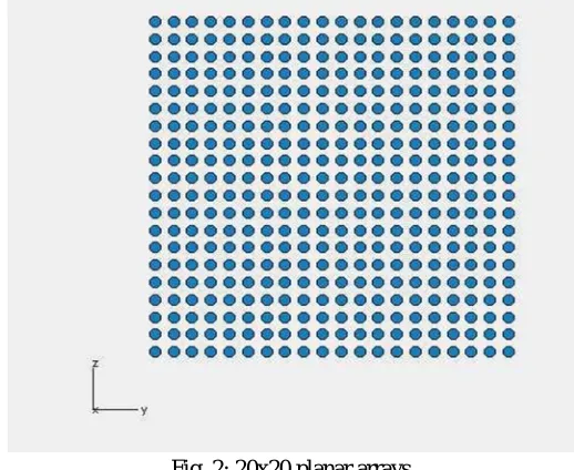
Fig. 2: 20x20 planar arrays
[image:3.612.175.434.474.686.2]Technology (IJRASET)
V. MATLAB SIMULATION RESULTS
[image:4.612.114.503.122.308.2]A. Results of Radiation Pattern
Fig. 3: Radiation pattern when distance between elements is 0.25
[image:4.612.136.480.367.502.2]In the above figure, the radiation pattern of normalized plot and polar plot have shown when the distance between the elements is 0.25.The number of elements is 400.The obtained gain is 0.965 with minimum side lobes.
Fig. 4: Radiation pattern when distance between elements is 0.5
In the above figure, the radiation pattern of normalized plot and polar plot have shown when the distance between the elements is 0.5.The number of elements is 400.The obtained gain is 0.8.The gain is decreased and sidelobes are increased as per the previous radiation pattern.
[image:4.612.136.479.573.706.2]Technology (IJRASET)
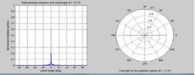
[image:5.612.135.481.116.270.2]In the above figure, the radiation pattern of normalized plot and polar plot have shown when the distance between the elements is 0.75.The number of elements is 400.The obtained gain is 0.6.The gain is decreased and sidelobes are increased as per the previous radiation patterns.
Fig. 6: Radiation pattern when distance between elements is 1
In the above figure, the radiation pattern of normalized plot and polar plot have shown when the distance between the elements is 1.The number of elements is 400.The obtained gain is 0.38 with side lobes. The gain is decreased and sidelobes are increased as per the previous radiation patterns.
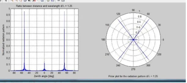
Fig. 7: Radiation pattern when distance between elements is 1.25
In the above figure, the radiation pattern of normalized plot and polar plot have shown when the distance between the elements is 1.25.The number of elements is 400.The obtained gain is 0.18 with greater side lobes. The gain is decreased and side lobes are increased as per the previous radiation patterns.
From above, we conclude that when the distance between the elements increases, gain decreases and side lobes increases. To get better gain, the distance between the elements should be minimum.
VI. CONCLUSION
In conclusion, this presents several new approaches to the design of phased arrays with reduced complexity. As mentioned before, phased array antenna systems have traditionally been in use for military applications in the past several decades. However, there has also been recent growth in civilian radar-based sensors and advanced communication systems that have drawn an increasing interest in utilizing phased array technologies for commercial applications. Phased array, capable of providing a directional beam that can be electronically steered, can significantly enhance the performance of sensors and communications systems.The spatial selectivity of phased arrays can increase the channel capacity and data rate without requiring extra bandwidth.
VII. ACKNOWLEDGEMENT
[image:5.612.155.461.334.471.2]Technology (IJRASET)
REFERENCES
[1] W.G. William, J.M. Hui, M. Bell, F. Iskander, and J. J. Lee, ”Low-Cost Microstrip-Line-Based Ferrite Phase Shifter Design for Phased Array Antenna Applications Highgain,” IEEE Antennas and Wireless Propagation Letters, vol. 6, pp. 86-89, 2007.
[2] S. Wanner, R.J. Weber, and J.M. Song, “Mutual coupling in phased array,” IEEE APS International Symposium, Honolulu, Hawaii, pp. 153-156, Jun. 2007.
[3] H. Chiu, C. Cheng, R.D. Murch, and C.R. Rowell, “Reduction of Mutual Coupling Between Closely-Packed Antenna Elements,” IEEE Transactions on Antennas and Propagation, vol. 55, no. 6, pp. 1732-1738, Jun. 2007.
[4] S. Wanner, S. Sekar, Bruce Fu, R.J. Weber, and J.M. Song, “Phased Array System Design and Modeling,” International Symposium on Signal Systems and Electronics, Montreal, B.C., Canada, pp. 455-458, Jul. 2007.
[5] S Nagakishore Bhavanam and Manjoor Syed, 2014. “A Novel Algorithm for Satellite Image Resolution Enhancement Using Wavelet-Domain Approach Based On (DT-CWT) and Non Local Means (NLM)”. International Journal of Engineering and Technical Research (IJETR), Vol.2 Issue-9, September 2014, ISSN: 2321-0869, pp.312-315.
[6] S Nagakishore Bhavanam, M. Sekhar and Dr. P. Siddaiah "Triple Frequency Circular Patch Antenna". IEEE Publications, ISBN: 978-1-4799-3975-6 (IEEE Xplore), 978-1-4799-3974-9 (CD), 978-1-4799-1594-1 (Print), pp.1231-1233.
[7] L. Xin, H. Xiujiang, and N. Zaiping, “Equivalent Relations Between Interchannel Coupling and Antenna Polarization Coupling in Polarization Diversity Systems,” IEEE Transactions on Antennas and Propagation, vol. 55, no. 6, pp. 1709-1715, Jun. 2007.
[8] W.L. Liu, T.R. Chen, S.H. Chen, and J.S. Row, “Reconfigurable microstrip antenna with pattern and polarization diversities,” Electronics Letters, vol. 43, no. 3, Part 2, pp. 1009-1012, Mar. 2007.
[9] T. Brown, S.R. Saunders, S. Stavrou, and M. Fiacco, “Characterization of Polarization Diversity at the Mobile,” IEEE Transactions on Vehicular Technology, vol. 56, no. 9, pp. 2440-2447, Sept 2007.
[10] K.C. Wan and Q. Xue, “Indirect Controlled Phased Source,” IEEE Microwave and Wireless Components Letters, vol. 16, no. 12, pp. 702-704, Dec. 2006. [11] S Nagakishore Bhavanam and Vasujadevi M “Video Improvement Technique for Vibrating Video signals in Surveillance Applications”. International Journal
on Recent Trends in Engineering and Technology (IJRTE), Vol.5, No.2, ISSN 2158-5563 (Online); ISSN 2158-5555 (Print), March 2011, Published jointly by USA, ACEEE, AMAE, ACEE, Florida. pp.116-121.
[12] S Nagakishore Bhavanam “FPGA Implementation of Distributed Arithmetic for FIR Filter”. International Journal of Engineering Research & Technology (IJERT), Vol.1, Issue.9, November 2012, ISSN: 2278-0181, pp.1-8.
[13] S Nagakishore Bhavanam and Vasujadevi M “Printed Microstrip Compact Antenna with Slots in Ground Plane and Patch using HFSS”. International Journal of Engineering Research and Sports Science (IJERSS), Vol. 1, Issue. 2, Feb 2014, ISSN: 2348-1404(online), ISSN: 2348-2400(print), pp.19-24.
[14] G Naveen Kumar, S Nagakishore Bhavanam and Vasujadevi M “Image Hiding in a Video-based on DWT & LSB Algorithm”. Elsevier Publications 2014, ISBN: 978-93-5107-228-7, pp.7-12.
[15] S Nagakishore Bhavanam “Multi Scale Decomposition and Edge Preserving Filter Based Satellite Image Resolution Enhancement - A Review”. International Journal of Innovative Research In Electrical, Electronics, Instrumentation And Control Engineering (IJIREEICE), Issue 7, Vol.2, July 2014, ISSN (Print): 2321-5526, ISSN (Online): 2321-2004, pp. 1696-1699.
[16] Vasujadevi M, S Nagakishore Bhavanam, and Dr. P. Siddaiah " Rectangular Patch Antena Aray Design at 13GHz frequency Using HFSS ". IEEE Publications, ISBN: 978-1-4799-3975-6 (IEEE Xplore), 978-1-4799-3974-9 (CD), 978-1-4799-1594-1 (Print), pp. 43-46.
[17] Vasujadevi M and S Nagakishore Bhavanam “Design of Vivaldi Antenna - By Using COMSOL Multiphysics Software", Acharya Nagarjuna University Journal of Engineering & Technology (ANUJET), Vol.6, No. 1 &2, July-Dec 2014, ISSN: 0976-3414, pp.1-7.
[18] S Nagakishore Bhavanam, Dr. P. Siddaiah and M. Vasujadevi "Rectangular Patch Antenna Array Design at 13GHz Frequency Using HFSS 14.0". Springer India : Advancements of Medical Electronics, Chapter : 24, ISSN : 2195-2728, ISBN : 978-81-322-2255-2, ISBN : 978-81-322-2256-9 (eBook), Springer Book Publications, January 2015, pp.263-270.
[19] S Nagakishore Bhavanam et al, “Design & Simulation of single frequency Rectangular Patch Antenna by Using HFSS”. International Journal of Engineering Research and Applications (IJERA), Vol. 5, Issue 4, Part-V, April 2015, ISSN : 2248-9622, pp.06-09.
[20] S Nagakishore Bhavanam, and B. Lakshmi Narayana "Design & Simulation of Tripple Frequency Triangular Patch Antenna by Using HFSS 14.0", International Journal of Applied Engineering Research, vol. 10, No. 20 April 2015, ISSN : 0973-4562(print), ISSN : 1087-1090 (Online), pp. 18585-18588. [21] S Nagakishore Bhavanam, Vasujadevi M, B Bhaskara rao and V Krishna Naik “Design of a Practical Type Transmission Lines by using COMSOL