5
IX
September 2017
“Study of Behavior of RC Frame Building for
Different Seismic Zone”
Manohar R S1, Kavan M R2 1
PG Student, Dept. of CivilEngg, AIT, Chikkamagaluru, Karnataka, India 2
Assistant Professor, Dept. of Civil Engg, AIT, Chikkamagaluru, Karnataka, India
Abstract: When a structure is constructed in a seismic zone it gets affected from seismic zones mainly in three perpendicular directions. By this the structure starts to vibrate in all the three directions. It is important to consider the base shear and storey drift while designing the structure especially in tall structures and sky scrapers. Designing the structures should be behaved like elastically during earthquakes without damaging the structure and while designing a structure various factors should be taken into consideration. In this project a structure is taken into consideration for various zone factors by keeping soil medium and storey heights are constant and analyzed usingetabs software.
Keywords: Seismic Zones, Storey Drift, Base Shear.
I. INTRODUCTION
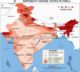
Based on the intensity of the earthquake which is happened in the previous time, the zones are revised from time to time and the new codes are added to it. The seismic zones are mainly classified into four different zones from zone II, zone III, zone IV and zone V. Zone V are the areas of having the highest risks zone which suffers maximum earthquake intensities. The Indian standard code allocates the zone factor 0.36 for the zone V region. The structural engineers will use these zone factors for designing the building. The zone IV is called as high damage risk region. The Indian standard code assigned zone factor for zone IV is 0.24. Zone III is categories as moderate damage risk region and the code assigned by the Indian standard for zone III is given as 0.16. Zone II categories as low damage risk region and the Indian standard assigns the zone factor for the zone II is 0.1.
[image:2.612.149.463.432.715.2]II. DIFFERENT SEISMIC ZONES IN INDIA:
885
©IJRASET (UGC Approved Journal): All Rights are ReservedIII. FACTORS USED TO DETERMINE THE SEISMIC COEFFICIENT: A. Zone Factors, Z
This factor is used to obtain in the design seismic force depending upon the functional use of the structure. The zone factors which are included in this standard are reasonable for the estimate of effective ground acceleration.
Table 1.1: List of Zones Factor
Zones Intensity Zone Factor
Zone II Least Active Seismic Zone 0.1
Zone III Moderate Seismic Zone 0.16
Zone IV High Seismic Zone 0.24
Zone V Highest Seismic Zone 0.36
B. Importance Factor, I
It is used to obtain from the design loads for building and other structures and it is based on the occupancy of the category. It is used to calculate flood, wind, snow, earthquakes and ice loads etc., the importance factor can be used as a multiplier that increases or decreases the base design loads.
C. Response Reduction Factor, R
The factor caused due to reflect the ability of the structure to be the elastic behavior. This depends on the seismic damage of the structure characterized by ductile deformation.
D. Average Response Acceleration Coefficient, Sa/g
According to IS 1893 (part 1): 2002, the seismic activity depends on the area of zone factor and the average coefficient acceleration of the soil response and it will reorganize depends upon the type of foundation.
IV. OBJECTIVES OF THE PROJECT
A. Analysis of RC frame building by for all the earthquake zones.
B. Comparison of the models for different parameters like base shear and storey drift by developing graphs and tables.
V. METHODOLOGY
Define material properties for steel and concrete
Define sectional properties for columns and beams
Define slab sections and wall thickness
Placement of columns, beams and slabs in the grid system
Define the load patterns for earthquake, change in the modify lateral load for various zones, zones factor, reduction factors,
time period, importance factor and site type
Assign the load to the frames and shells of the building Define load combinations
Analyze and Run the program
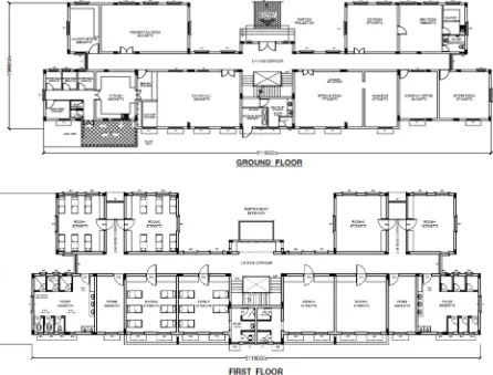
VI. TYPES OF PHASE A. Modeling Phase
[image:4.612.79.525.147.486.2]It is the phase where the structure should be analyzed properly weather the structure is comes in the seismic zone or not before constructing. In the present case the structure is taken for a certain height which is comes in the seismic zone and it has been analyzed using the etabs software.
[image:4.612.56.545.540.721.2]887
©IJRASET (UGC Approved Journal): All Rights are ReservedB. Analysis Phase
In this phase the loads are applied on the frames and the slabs before analyzing the structure in the software.The bending moment, shear force, axial forces are obtained for each and every point of the element and the maximum value also obtained.Following data are considered for the analysis of the structure.
Fig1.4:Deformed shape of the structure
VII. RESULTS A. A]storey drift
In the present study the storey drifts is done for the different zonal conditions and it has been evaluated by using etabs software. Table1.2: Storey Drift (mm) Along X – Axis
Storey Zone II Zone III Zone IV Zone V
Base 0 0 0 0
Storey 1 0.000672 0.001186 0.001694 0.003114
Storey 2 0.000994 0.001755 0.002507 0.004608
Storey 3 0.000821 0.001449 0.002072 0.003808
Fig 1.5: Storey Drift in X-Direction for Different Zones
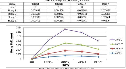
Table 1.3: StoreyDrift (Mm) Along Y – Axis
Storey Zone II Zone III Zone IV Zone V
Base 0 0 0 0
Storey 1 0.000834 0.001459 0.002102 0.003874
Storey 2 0.001336 0.002342 0.003372 0.006214
Storey 3 0.001185 0.002076 0.002991 0.005511
Storey 4 0.000812 0.001414 0.002041 0.00376
Fig 1.6: StoreyDrifts in Y-Direction for Different Zones
1) Discussions: From the above tabular columns and the graphs it is seen that the values which are obtained are for the storey drifts in both x and y direction. The storey drifts varieties from zone II to zone V. The storey drifts usually occurs in between the two floors, here in this building the storey drifts is maximum in the storey 2 of the building. The obtained storey drifts values are within the prescribed limits given by the Bureau of Indian Standards.
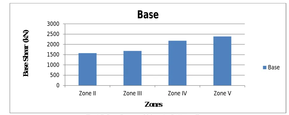
B. B]base shear
The base shears are done here for the building having the same soil conditions but changing in zone factors. As the zone regions gets changing the base shear also gets changing. The values for the various seismic zones are mentioned below in the table.
Table 1.4: Maximum Base Reaction Values (kN) for Different Zones
Zone II Zone III Zone IV Zone V
Base (kN) 1576.657 1684.45 2177.322 2387.523
0 0.002 0.004 0.006 0.008 0.01 0.012
Base Storey 1 Storey 2 Storey 3 Storey 4
Zone V Zone IV Zone III Zone II Storey S tor y D ri ft ( m m ) 0 0.002 0.004 0.006 0.008 0.01 0.012 0.014
Base Storey 1 Storey 2 Storey 3 Storey 4
[image:6.612.69.554.677.719.2]889
©IJRASET (UGC Approved Journal): All Rights are ReservedFig 1.7: Base Reaction Values for Different Zones
1) Discussions: The base reaction values which are obtained above are from the building but situated in the different zones. As the zones are changing, the base reaction values are also gets increasing.
VIII. CONCLUSION
The present study conclude for the storey drifts and base shear parameters in the different zone are given by consideringfor RC Framed structure and the conclusions are given below
A. The storey drift value for the building varies from 0 to 0.000518 mm in the zone II region and it varies from 0 to 0.00376 mm in
the zone V region and all the values are well within the permissible limits.
B. As the seismic zone factor increases, the base shear of the building also increases. For the zone II region the base shear value is
1576.7 kN and it is increased to 2387.5 kN in zone V region.
REFERENCES
[1] HardikBhensdadia, Siddharth Shah [2015], “Pushover Analysis of RC Frame Structure with Floating Column and soft storey in Different Earthquakes Zones”, International Journal of Research in Engineering and Technology (IJRET), ISSN: 2321-7308, Vol. 04, Issue 04, April 2015.
[2] Arvind S Munoli, Dr. M S Kalappa [2015], “Evaluation of RC Frame Building under Seismic Loading and Base Isolation”, International Journal for Scientific Research and Development (IJSRD), ISSN: 2321-0613, Vol. 03, Issue 05, 2015.
[3] Bhola M Sontakke, Ashish S Moon [2015], “Seismic Analysis of Soft Storey RC Building during Earthquake”, International Journal on Recent and Innovation Trends in Computing and Communication, ISSN: 2321-8169, Vol. 03, Issue 02, February 2015.
[4] SomaniKishangopal J, SangavePrakash A [2015], “Seismic Response of RC Framed Buildings with Open Ground Storey”, International Journal of Engineering Research and Applications (IJERA), ISSN: 2248-9622, Vol. 05, Issue 02, February 2015.
[5] Mohammed Umar Farooque Patel, A V Kulkarni [2014], “A Performance Study and Seismic Evaluation of RC Frame Buildings on Sloping Ground”, IOSR Journal of Mechanical and Civil Engineering (IOSR-JMCE), ISSN: 2320-334X, 2014.
[6] Mr. Raghavendra S Deshpande, Dr. Mrs. Surekha A Bhalchandra [2014], “Seismic Analysis of Reinforced Concrete Building with Soft First Storey”, International Journal of Scientific and Engineering Research (IJSER), ISSN: 2229-5518, Vol. 05, Issue 05, May 2014.
[7] Deepak Soni, Dr. S K Dubey [2014], “Dynamic Analysis of Reinforced Concrete Framed Buildings under Non Linear Analysis”, International Journal of Engineering Development and Research (IJEDR), ISSN: 2321-9939, Vol. 02, Issue 04, 2014.
[8] HaroonRasheedTamboli, Umesh N Karadi [2012], “Seismic Analysis of RC Frame Structure with and without Masonry Infill Walls”, International Journal of Natural Sciences, ISSN: 0976-0997, Vol. 03, Issue 14, October 2012.
[9] IS: 456 - 2000, “Indian Standard plain and Reinforced Concrete Code of Practice”.
[10] IS: 1893 (part 1) – 2002, “Indian Standard Criteria for Earthquake Resistant Design of Structures part 1 General Provisions and Buildings”. [11] IS: 875 (part 1) – 1987, “Indian Standard Code of Practice for Design Loads for Building and Structures”.
[12] IS: 875 (part 2) – 1987, “Indian Standard Code of Practice for Design Loads for Building and Structures”. [13] IS: 875 (part 5) – 1987, “Indian Standard Code of Practice for Design Loads for Building and Structures”.
0 500 1000 1500 2000 2500 3000
Zone II Zone III Zone IV Zone V