International Journal of Emerging Technology and Advanced Engineering
Website: www.ijetae.com (ISSN 2250-2459,ISO 9001:2008 Certified Journal, Volume 3, Issue 7, July 2013)
473
Studies on Quasi-Z-Source-Based Three-Phase Isolated DC/DC
Converter for Distributed Power Generation
Vijaya Kumari H. C.
1,
H. N. Suresh
2,
S. Dhamodharan
31,2
Department of Electrical & Electronics Engineering, Malnad College of Engineering, Hassan - 573202
3Adroit Solutions, Bangalore
Abstract– Distributed generation is an emerging concept in the electricity sector, which represents good alternatives for electricity supply instead of the traditional centralized power generation concept. Among different distributed generation schemes, fuel cell is expected play a big part due to its inherent advantages. The power density of the quasi-Z-source-based single-phase isolated DC/DC converter is increased by quasi-Z-source-based three-phase isolated DC/DC converter. The present paper describes novel quasi-Z-source-based three-phase isolated DC/DC converter for distributed power generation. It contains voltage-fed quasi-Z-source inverter with continuous input current on the primary side, a three-phase isolation transformer and a three-three-phase voltage doubler rectifier. The model of the quasi-Z-source-based isolated DC/DC converter is simulated in the MATLAB. Simulated data related to gate signals of quasi-Z-source inverter, voltage from fuel cell, DC-link voltage, primary & secondary voltage from the isolation transformer, output voltage from the voltage doubler rectifier are used to test the performance of the quasi-Z-source-based DC/DC converter.
Keywords - DC/DC converter, Fuel cell, Quasi-Z-source inverter, Rectifier.
I. INTRODUCTION
Distributed generation represents a small-scale electric power source connected directly to the utility’s distribution network and provides electric power at a site closer to the customer, rather than through lengthy transmission lines spanning from central power stations. When it is fully implemented, can provide reliable, high quality and low-cost electric power. The different schemes that are available for distributed generation are solar energy, wind energy, micro-turbines and fuel cells [1]. Among these, fuel cells are the modern approach to distributed power generation due to low emission, simplicity, flexibility and silence advantages [2].
A voltage matching converter interconnects the low-DC-voltage producing fuel cell to residential loads. Fig. 1 represents the typical structure of two stage interface converter suitable for such purposes.
[image:1.612.339.548.243.348.2]
Fig. 1: Typical structure of the interface converter for residential fuel cell-powered systems.
The basic voltage matching converters are voltage-source pulse width modulated inverter with the step-up transformer and rectifier. The drawback of this scheme is the forbidden of the shoot-through period. Alternately, combination of the front-end boost converter with the voltage-source pulse width modulated inverter can be resorted for a similar purpose [3]. The drawback associated with this alternate scheme is the complicated control & protection algorithm and reduced reliability due to increased number of switching devices. In this context, the impedance-source (Z-source) inverter based topologies provide a modern approach to the step-up voltage conversion techniques. The main feature of the Z-source inverter [4] is that it can boost the input voltage by introducing a shoot-through operation mode. It means the simultaneous conduction of both the switches of the same phase leg of the inverter, which is forbidden in traditional voltage source inverter.
The work reported in this paper develops a novel quasi-Z-source-based three-phase isolated DC/DC converter for distributed generation which contains voltage-fed quasi-Z-source inverter with continuous input current on the primary side, a three-phase isolation transformer and a three-phase voltage doubler rectifier [5].
International Journal of Emerging Technology and Advanced Engineering
Website: www.ijetae.com (ISSN 2250-2459,ISO 9001:2008 Certified Journal, Volume 3, Issue 7, July 2013)
474
II. OVERVIEW OF QUASI-Z-SOURCE-BASED THREE-PHASE ISOLATED DC/DC CONVERTER
[image:2.612.326.557.191.474.2]The quasi-Z-source-based three-phase isolated DC/DC converter circuit topology is shown in Fig. 2. The quasi-Z-source network consists of two capacitors C1 and C2, two inductors L1 and L2 and a diode D1.
Fig. 2: The quasi-Z-source-based three-phase isolated DC/DC converter scheme.
The high-frequency isolation transformer provides the required voltage gain, as well as the galvanic isolation of the input and output sides of the converter. Transformer’s primary winding is connected to the output terminals of quasi-Z-source inverter, while the secondary side is connected to the voltage doubler rectifier. Compared to single-phase intermediate AC-link, the resulting advantages of the three-phase intermediate AC link over the single-phase AC-link are
Lower R.M.S. current through the inverter and
rectifier switches
Reduced isolated transformer’s volume (and weight) due to reduced overall yoke volume and reduced voltage and magnetic stresses
Reduced ratings of passive components of the quasi-Z-source network due to an increase by a factor of three of its operating frequency
Windings of isolation transformers in the three-phase isolation transformer stack, which could be connected in different configuration to obtain the desired output voltage.
2.1 Operating modes of the quasi-Z-source-based three-phase DC/DC converter
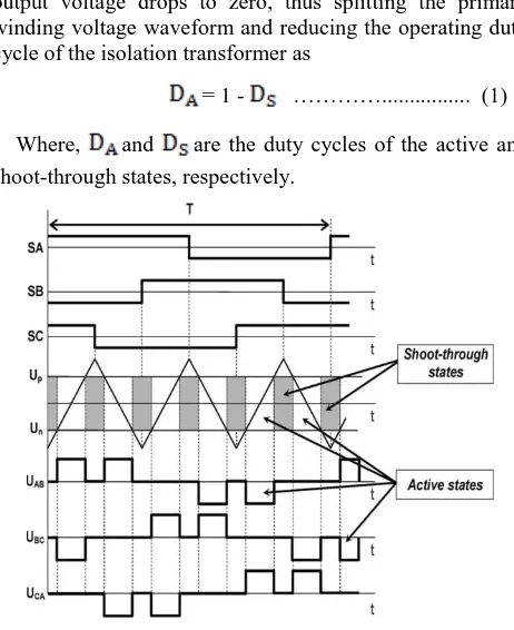
The operating principle of the three-phase quasi-Z-source inverter in the shoot-through (voltage boost) mode is shown in Fig. 3. SA, SB, and SC represent the theoretical switching pattern of the traditional three-phase voltage source inverter with 120◦ shifted control signals. To control the shoot-through states two reference signals (Up and Un) are introduced as shown in Fig. 3. If the triangular waveform is greater than Up or lower than Un, the inverter switches turn into the shoot-through state.
The resulting line voltages of the primary winding of the isolation transformer during the shoot-through states are
presented as , and as shown in Fig. 3. It is
noticeable that, during the shoot-through, the inverter output voltage drops to zero, thus splitting the primary winding voltage waveform and reducing the operating duty cycle of the isolation transformer as
= 1 - …………... (1)
Where, and are the duty cycles of the active and
shoot-through states, respectively.
Fig. 3: Operating principle and resulting voltages of the three-phase quasi-Z-source inverter in the shoot-through mode.
The main idea implemented in the quasi-Z-source-based converter is to keep the DC-link voltage ( ) constant despite the variation of voltage of the fuel cell. By keeping the DC-link voltage constant, the PWM inverter can be operated with a fixed duty cycle. According to the input voltage (fuel cell voltage), the discussed DC/DC converter operates either in shoot-through or non-shoot-through operation mode. If the fuel cell voltage drops below the predefined DC-link voltage level, the converter begins to operate in the shoot-through mode. During non-shoot-through operation mode the quasi-Z-source-based DC/DC converter acts as a traditional voltage source inverter.
III. SIMULINK MODEL OF QUASI-Z-SOURCE-BASED
DC/DC CONVERTER
The quasi-Z-source-based three-phase isolated DC/DC
converter with DC machine load developed in the MATLAB
[image:2.612.68.269.219.296.2]International Journal of Emerging Technology and Advanced Engineering
Website: www.ijetae.com (ISSN 2250-2459,ISO 9001:2008 Certified Journal, Volume 3, Issue 7, July 2013)
475
[image:3.612.332.544.111.434.2]The following are the quasi-Z-source three-phase DC/DC converter parameters assigned during simulation: C1 = C2 = 240µF, L1 = L2 = 50µF, C3 = C4 = 10µF. The isolation transformer has the turns ratio of 1:1. The controller part in the simulation model of quasi-Z-source-based three-phase isolated DC/DC converter generates gate signals to the IGBT/diode of quasi-Z-source inverter. The controller model part shown in Fig. 5 is developed according to the operating principle discussed in Fig. 3. It consists of control of active & zero states and control of shoot-through states.
[image:3.612.339.538.133.302.2]Fig. 4: Simulation model of quasi-Z-source-based three-phase isolated DC/DC converter.
Fig. 5: Controller model developed in the present work.
[image:3.612.57.277.253.528.2]In control of active and zero states, pulse width generators provide gate signals for all the transistors. Fig. 6 and Fig.7 shows the T1, T3 & T5 and T2, T4 & T6 gate signals with no shoot-through period.
Fig. 6: Transistors T1, T3 and T5 gate signals without shoot- through period.
Fig. 7: Transistors T2, T4 and T6 gate signals without shoot- through period.
IV. RESULTS AND DISCUSSIONS
Fig. 8 shows the input and DC-link voltages of the quasi-Z-source-based three-phase isolated DC/DC converter working during shoot-through mode operation, as presented in literature [5]. Fig. 9(a) and Fig. 9(b) shows the input and DC-link voltages obtained in the present work, through
MATLAB simulation during shoot-through operation mode.
The input adopted is 40V DC supply derived from a fuel cell. The 80V DC-link voltage obtained is due to the effect of shoot-through period present in the gate signals of quasi-Z-source inverter network.
Control of active and zero states
[image:3.612.62.279.259.371.2] [image:3.612.76.266.398.528.2]International Journal of Emerging Technology and Advanced Engineering
Website: www.ijetae.com (ISSN 2250-2459,ISO 9001:2008 Certified Journal, Volume 3, Issue 7, July 2013)
[image:4.612.76.269.140.257.2]476
Fig. 8: 40V input and 80V DC-link voltages during shoot-through mode operation presented in literature [5].
(a)
(b)
Fig. 9: 40V input and 80V DC-link voltages obtained during
shoot-through mode operation shoot-through MATLAB simulation in the present
work
Similarly, in the next section other basic operating waveforms of the DC/DC converter are simulated in
MATLAB as described in the literature [5]. Fig. 10 shows
the primary winding voltages , and of
isolation transformer obtained in MATLAB simulation.
[image:4.612.333.547.145.349.2]During through period operation mode, the shoot-through state duty cycle is 0.25 and active state duty cycle is 0.75.
Fig. 10: The primary winding voltages , and of
isolation transformer obtained through MATLAB simulation in the
present work, during shoot-through operation mode.
Fig. 11(a) and Fig. 11(b) show the 80V secondary winding voltage isolation transformer and 160V DC output voltage from the voltage doubler rectifier upon MATLAB
simulation in the present work.
(a)
(b)
Fig. 11: 80V secondary winding voltages of isolation transformer and 160V output voltage from voltage doubler rectifier obtained upon
MATLAB simulation in the present work during shoot- through mode
operation.
[image:4.612.70.268.298.528.2] [image:4.612.340.536.456.651.2]International Journal of Emerging Technology and Advanced Engineering
Website: www.ijetae.com (ISSN 2250-2459,ISO 9001:2008 Certified Journal, Volume 3, Issue 7, July 2013)
477
Fig. 12 shows the 80V secondary winding voltage and 160V output voltage from the voltage doubler rectifier during non-shoot-through operating mode obtained upon
MATLAB simulation in the present work. During
non-shoot-through operation mode the input applied to the converter is 80V and it is derived from fuel cell.
(a)
[image:5.612.75.258.212.374.2](b)
Fig. 12: 80V secondary winding voltage and 160V output voltage
obtained during non-shoot-through period upon MATLAB
simulation in present work.
The simulation results shows that the quasi-Z-source-based three-phase isolated DC/DC converter improve the isolation transformer turns ratio (turns ratio is 1:3.75 in case of single-phase [5] and in case of three-phase it is 1:1). Finally the quasi-Z-source-based three-phase isolated DC/DC converter is relatively more efficient converter than the converters involving voltage source inverter.
V. CONCLUSION
In the present work, the quasi-Z-source-based isolated DC/DC converter has been successfully applied for distributed power generation. Important conclusions that are drawn out of the investigations made in the present work are:
The quasi-Z-source inverter implemented on the
primary side of the quasi-Z-source-based isolated DC/DC converter can boost the input voltage by introducing a shoot-through operation mode. It provide voltage boost and buck functions only by use of a special control algorithm.
The quasi-Z-source-based three-phase isolated DC/DC
converter is updated version of the quasi-Z-source-based single-phase isolated DC/DC converter which improves the power density of the quasi-Z-source-based single-phase isolated DC/DC converter.
The isolation transformer provides the voltage gain and input-output galvanic isolation.
The turns number of the secondary winding of the isolation transformer is reduced due to the voltage doubling effect available with the voltage doubler rectifier.
REFERENCES
[1] Haiping Xu, Li Kong, and Xuhui Wen, “Fuel cell power system and high Power DC–DC converter,” IEEE Transactions on Power Electronics, vol. 19, no. 5,Septmber 2004.
[2] B.J.Holland, J.G. Zhu, and L. Jamet, “Fuel cell technology and
application,” available at:
http://services.eng.uts.edu.au/cempe/subjects_JGZ/eet/AUPEC01_11 1.pdf
[3] W. Choi, P. Enjeti, and J. W. Howze, “Fuel cell powered UPS systems: Design considerations,” available at: http://enjeti.tamu.edu/journal-papers/fuelcellupsdesign.pdf
[4] Fang Zheng Peng, “Z-source inverter,” IEEE Transactions on Industry Applications, vol. 39, no. 2, March/April 2003.


![Fig. 8: 40V input and 80V DC-link voltages during shoot-through mode operation presented in literature [5]](https://thumb-us.123doks.com/thumbv2/123dok_us/8728114.885994/4.612.70.268.298.528/fig-input-link-voltages-shoot-operation-presented-literature.webp)

