Dimensional Accuracy of Additive Manufacturing Model with Different
Internal Structure for Investment Casting Implementation
M. Ibrahim
1,aand M.N. Hafsa
2,b1,2Department of Manufacturing and Industry Engineering, Faculty of Mechanical and Manufacturing Engineering, UniversitiTun Hussein Onn Malaysia, BatuPahat, Johor, Malaysia.
a[email protected],b[email protected]
Keywords:Additive Manufacturing, Fused Deposition Modeling, Investment Casting, Multi-Jet Modeling
Abstract.Additive Manufacturing (AM) technology has evolved in manners that are towards diverse possible application. One of AM application is as a sacrificial pattern for Investment Casting (IC) process. The study is focusing on the ability of a Polylactic Acid (PLA) and VisiJet®acrylic material to produce an IC patterns with good dimensional accuracy for ceramic shell fabrication. The AM part is fabricated with a variety of different processes, different internal structure pattern, and different part builds orientation. The AM fabricated parts were then analyzed using the Coordinate Measuring Machine (CMM) to get the average dimension deviation. The results show that part built with 0º built orientation produced a better result compared to part built with 90º built orientation regardless of its internal structure pattern. Even so, among the different internal structure patterns, part with cross internal patternstructure produce better accuracy compared to the others.
Introduction
AM technology is relatively new and has developed with diverse research activity to implement AM in every possible manufacturing process. Its implementation in the IC is one of development in AM technology. Traditionally, the wax IC pattern was prepared using an injection molding process. In AM implementation of IC process, it could be done in direct and indirect approach. With indirect method, AM is used to fabricate a mold for wax production, while with direct method, AM is used to fabricate the pattern for ceramic shell preparation in IC process. Direct method could eliminate rapid tooling technology, which is more cost effective [1]. However, non-wax materials such as Acrylonitrile Butadiene Styrene (ABS), epoxy and acrylic have shown problems such as shell cracking during de-waxing process [2].
The Visijet® materials have the ability to address a wide range of applications. By using the Visijet® material, the post processing of the fabricated parts is much easier and the finished product is castable, and could be further processed such as painting, plating, sanding, and drilling. The PLA build material filament is a biodegradable plastic that was derived from corn and commonly used in many types of packaging [3]. PLA material could be considered as a more 'earth friendly' plastics compared to petroleum based ABS. The material is pretty easy to use and performs well on most prints. The material has the tendencies to stick to itself, which helps during the fabrication process.
Methodology
A stair was selected considering the simple design and the prototype will incorporate hollow and quasi hollow (cross, hatch and square) inner structure for support pattern. Part internal structures were designed by Computer Aided Design (CAD) software due to ProJet™ SD3000 3-D Printer machine and MakerBot® Replicator™ 2 Desktop 3D Printer does not offer a modification of internal structure. The SolidWorks DWG file is converted to an STL file to be used in AM software. In this research, the selected parameter to construct this part is 0º build orientation and 90º build orientation as in Figure 1(a). The layer resolution setting was fixed at low resolution, which is 0.00158 inches (MJM) and 0.0118 inches for FDM. The MJM part was fabricated using VisiJet® SR200 as build material and VisiJet® S100 as the support material, while Polylactic acid was used for the FDM part. For each of the internal structure design, three samples are being fabricated, with two builds orientation, the total of twenty-four samples are made using MJM technique and another twenty-four samples using the FDM technique.
The specimens were measured at three random locations for each surface using Carl Zeiss model Spectrum 700 coordinate measuring machine that are capable to measure up to five decimal places. Figure 1(b) generally shows the locations for the dimensional measurement. The part dimension is taken using the “face-to-face” test schemes, according to the ISO 10360-2:2009 standard.
Figure1.(a) Part orientation construction(b) Dimensional accuracy measurement
Result and Discussion
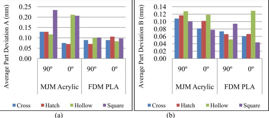
After the measurement was completed, the value from the three locations was turned into an average value, then the measured distance between the surfaces were used to get the dimension for the specimens. These steps were done to the entire specimen that total of forty-eight pieces, from three specimens for four internal pattern structure design, comparing between two build orientation of 0º and 90º. Figure 2 shows the total part average for every part with different internal structure for 90º and 0º build orientation that fabricated using MJM and FDM techniques. From Figure 2(a), the highest average part deviation occurs at the Square (MJM Acrylic - 90º build orientation) with the value of 0.23421 mm. The lowest average part deviation occurs at Hatch (MJM Acrylic - 90º build orientation) with the value of 0.07009 mm. Comparing the bar charts of the MJM fabricated part, the part fabricated with 0º build orientation produces stable results with the total part average 0.14081 mm while 90º build orientation is 0.15215 mm. For part made using FDM technique, the part with 90º build orientation produces stable and better result with the total part average 0.09011 mm while 0º build orientation is 0.09389 mm.
Figure 2(b) shows the highest average part deviation occurs at Hollow (FDM PLA - 0º build orientation) with the value of 0.12901 mm. The lowest average part deviation occurs at the Square (FDM PLA - 0º build orientation) with the value of 0.05168 mm. Among the MJM fabricated parts, the parts fabricated with 0º build orientation produce better results with total part average 0.09480 mm while 0.11341 mm for 90º build orientation. However, for the part made using FDM technique,
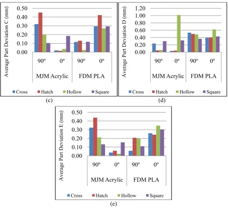
the part with 90º build orientation produces better result, even among both techniques with the total part average 0.07126 mm while 0º build orientation is 0.07493 mm.Figure 2(c) shows the highest average part deviation occurs at Hatch (MJM Acrylic - 90º build orientation) with the value of 0.45115 mm. The lowest average part deviation also occurs at Hatch (MJM Acrylic - 0º build orientation) with the value of 0.01525 mm. The total part average is high at MJM parts fabricated with 90º build orientation and FDM parts fabricated with 0 º build orientation. The highest total part average is calculated at FDM PLA - 0º build orientation with 0.32055 mm. It is followed by MJM Acrylic - 90º build orientation, FDM PLA - 90º build orientation and MJM Acrylic - 0º build orientation with the value of 0.26832 mm, 0.097454 mm and 0.06434 mm respectively.
Figure 2(d) shows the highest average part deviation occurs at Hollow (MJM Acrylic - 0º build orientation) with the value of 1.01536 mm while the lowest average part deviation occurs at Cross (MJM Acrylic - 0º build orientation) with the value of 0.03302 mm. The average values were calculated by accumulating the deviation from D1, D2 and D3 and divided by three. The highest total part average is at FDM PLA - 90º build orientation, followed closely by the FDM PLA - 0º build orientation and MJM Acrylic - 0º build orientation. The total part average values are 0.47102 mm, 0.46163 mm and 0.35315 mm. The lowest total part average value is 0.16096 mm at MJM parts with 90º build orientation, whichis best compared to the others.
Figure 2(e) shows the highest average part deviation occurs at Hatch (MJM Acrylic - 90º orientation) with the value of 0.43824 mm and the lowest average part deviation occurs at Hollow (MJM Acrylic - 0º orientation) with the value of 0.02351 mm. The total part average for MJM part is 0.27640 mm for part with 90º build orientation and 0.06828 for part with 0º build orientation which is the lowest average. The total part average for FDM part is 0.14342 mm for part with 90º build orientation 0.28823 mm for part with 0º build orientation which is the highest total part average.
From the Figure 2, parts with Cross and Hatch internal structure pattern has the tendency to shrink. This phenomenon also occurs in the study done by Idris, Sharif and Harun [6]. Inconsistency of dimensional deviation’s phenomena had occurred at different locations for MJM technique. It occurs due to the different internal pattern structure and part builds orientation [6,7]. The internal pattern structure plays a role during the part fabrication process. During the layer-by-layer process, there are probabilities that the presence of internal support could cause warping. It could occur at every edge or only at the one edge due to the upward curling of the part [7]. At the z-axis increment, the parts tend to expands compared to the x-axis and y-axis. This happens due to load pressure during the layer by layer process as the printer creates the model one layer at a time by spreading a layer of acrylic and printing a binder in the cross-section of the part using an inkjet-like process.
(a) (b)
0.00 0.05 0.10 0.15 0.20 0.25
90º 0º 90º 0º
MJM Acrylic FDM PLA
Average Part Deviation A (m
m
)
Cross Hatch Hollow Square
0.00 0.02 0.04 0.06 0.08 0.10 0.12 0.14
90º 0º 90º 0º
MJM Acrylic FDM PLA
Average Part Deviation B (m
m
)
[image:3.595.72.524.554.753.2](c) (d)
[image:4.595.71.526.66.480.2](e)
Figure 2. Average part deviation for MJM and FDM techniques
Conclusion
This research has shown the importance of producing quality AM patterns at the early stage of preparation for IC process. The study shows the needs of selecting the best build orientation when fabricating an MJM and FDM part, and the effect of different internal structures of the AM pattern. From the data of average part deviation for each internal structure at 90º and 0º built orientation for MJM Acrylic and FDM PLA on Table 1, the MJM parts build with 0º build orientation shows better accuracies with total part average of 0.14428 mm. The AM part of the closest nominal dimension was the parts of MJM Acrylic - 0º build orientation with cross internal pattern structure. The average part deviation was 0.04944 mm.
Table 1. The average part deviationfor each internal pattern structure at 90 º and 0º part orientation for MJM Acrylic and FDM PLA
Internal Pattern Structure
Average Part Deviation (mm) MJM Acrylic FDM PLA
90º 0º 90º 0º
Cross 0.22346 0.04944 0.17387 0.21923
Hatch 0.23651 0.05748 0.19444 0.24789
Hollow 0.14258 0.28107 0.17275 0.29076
Square 0.17445 0.18911 0.15753 0.23351
Total Part Average (mm) 0.19425 0.14428 0.17465 0.24785
0.00 0.10 0.20 0.30 0.40 0.50
90º 0º 90º 0º
MJM Acrylic FDM PLA
Average Part Deviation C (m
m
)
Cross Hatch Hollow Square
0.00 0.20 0.40 0.60 0.80 1.00 1.20
90º 0º 90º 0º
MJM Acrylic FDM PLA
Average Part Deviation D (m
m
)
Cross Hatch Hollow Square
0.00 0.10 0.20 0.30 0.40 0.50
90º 0º 90º 0º
MJM Acrylic FDM PLA
Average Part Deviation E
(m
m
)
[image:4.595.123.467.685.789.2]In general, all the AM techniques produced relatively good surface quality. It was found that different internal structures of AM patterns have an effect on the surface roughness of AM parts. It is important when it comes to implementing the AM pattern as the sacrificial pattern for IC process, as the quality features of the end product of investment casting depends on the quality feature of its pattern. After completing this project, it was found that some area of study that could be improved for future study. According to Yan &Gu [8], there are several ways to minimize the effect of shrinkage, by selection of appropriate manufacturing control parameters, development or exploration of materials with relatively small shrinkage or stress free properties, and stress relief methods. All these approaches require in-depth research on the materials and understanding of the processes.
Acknowledgement
The authors would like to thank UniversitiTun Hussein Onn Malaysia (UTHM) for their financial support and facilitating in the research programme.
References
[1]C.K. Chua, C. Feng, C.W. Lee, Rapid investment casting: direct and indirect approaches via model maker II, International Journal Advance Manufacturing Technology. 25 (2005) 26-32.
[2] M.N. Hafsa, M. Ibrahim, S. Sharif, M.F.M. Omar, M.A. Zainol, Evaluation on different internal structure and build orientation for multijet modeling process, Applied Mechanics and Materials. 315 (2013) 587-591.
[3]L. James, L.S. Andrew, Polylactic acid polymers from corn, Journal of Industrial Textiles. 29 (2000) 191-205.
[4] P.F. Jacobs, Rapid prototyping and manufacturing: fundamentals of stereolithography.SME Publication.1992.
[5] P.M. Dickens, R. Stangroom, M. Greul, B. Holmer, K.K.B. Hon, R. Hovtun, R. Neumann, S. Noeken, D. Wimpenny, Conversion of RP models to investment castings, Rapid Prototyping Journal. 1 (1995) 4-11.
[6]M.H. Idris, S. Sharif, W.S.W. Harun, Evaluation of ABS patterns produced from FDM for investment casting process, Proceedings of the 9th Asia Pacific Industrial Engineering and Management Systems Conference. (2008) 1299-1303.
[7]M.S. Ahmad, B.T.H.T. Baharudin, Z. Leman, N. Ismail, S. Sulaiman, Thermal parameter affects on the part built using 3D Printer Projet SD 3000, Advance in Materials and Processing Technologies XV. 773/774 (2013) 833-841.