Journal of Chemical and Pharmaceutical Research, 2014, 6(3):640-644
Research Article
CODEN(USA) : JCPRC5
ISSN : 0975-7384
Optimization method of complex electronic device test point
Xiaoqi Xing
1,2, Bin Liu
1,2and Dongyi Ling
1,21
Science & Technology on Reliability & Environmental Engineering Laboratory, Beijing, China
2School of Reliability and Systems Engineering, Beihang University, Beijing, China
_____________________________________________________________________________________________
ABSTRACT
In terms of complex electronic systems, in order to enhance the test efficiency and reduce the test cost, an optimization method of analog circuit test point combining with fault dictionary and branch and bound is proposed. It adopts fuzzy set and fault dictionary as tools, and takes fault detection and fault isolation as constraint condition, thus to build a 0-1 programming mathematical model for test point optimization, which is solved with branch and bound. Finally, it simulates and verifies the method with classical test optimization circuit. The simulation result indicates that the above method can realize rapid optimization of test point on the premise of guaranteeing the demand of fault diagnosis, providing guidance for test implementation.
Key words: complex electronic system; fault diagnosis; test point; test sample; fault dictionary; branch and bound _____________________________________________________________________________________________
INTRODUCTION
Complex electronic systems are usually with characteristics, such as large scale, long life cycle, key mission, high reliability, constant variation and complex network features. For example, take Integrated Modular Avionics (IMA) [1] as the typical representative, it is the highest stage of the development of avionic architecture currently. Complex electronic systems are with high rate of defect and cannot guarantee the reliability. A data survey made by the United States indicates that failure probability of F-22 is twice that of F-15 and F-16. Due to the existence of component tolerance, the test diagnosis of analog circuit is rather difficult; therefore, conducting researches on test diagnosis methods aiming at analog systems is significant.
The quality and efficiency of a diagnostic system depends on the fault information obtained from the system [2], while the sources of fault information are distributed among test points in the system. Considerable researches on fault diagnosis give tacit consent to the condition that test points have been reasonably configured in advance. In fact, restricted by the cost of overall test, configurable test resources and other factors, it is impossible to configure test resources and test for all test points. Through test point optimization, it is completely possible to obtain the fault resolution ratio as that obtains in the test of all the test points, by selecting those test point sets with the largest fault information. Recently, determining the optimal number of test points and its distribution for a specific diagnostic system has drawn attention from people [3].
CONCEPT OF FUZZY SET AND FAULT DICTIONARY
The selection principle of test point is to minimize the number of test points on the premise of isolating all faults in the fault set. Therefore, the selection process of test points is just the process of fault isolation. Fault isolation means all concentrated faults can be separated through test vectors, it usually has criterion as equation (1) [4].
∑𝑛𝑘=1[𝑉𝑘(𝑁𝑂𝑅) − 𝑉𝑘(𝐹𝑖)]2≥ 0.5𝑛 (1)
represents the number of test points. Due to the component tolerance,𝑉𝑘(𝑁𝑂𝑅) ,𝑉𝑘(𝐹𝑖) refer to an interval rather
than a point. Therefore, equation (1) cannot be directly used in reality. In order to solve this problem, divide each element value of each test vector into several regions, and the central value of each region represents the average value of adjacent elements. Then, expand 0.7 V for the central value to the left and right, in order to form an interval of test values, which is called fuzzy region. All fault modes falling in the same fuzzy region constitutes a fuzzy set. Different fuzzy sets can be separated with the number of fuzzy sets(𝑁𝑖, 𝐴𝑗). 𝑁𝑖represents the node number, and 𝐴𝑗 represents the j fuzzy set. All fuzzy sets of test points form the table of fuzzy sets, which reflects the division situation of fuzzy sets for each test point, and can be obtained through circuit simulation and division of fuzzy sets generally [5].
In the foregoing discussion about fuzzy sets, the number of fuzzy sets is defined in order to separate the corresponding fuzzy sets of different test points. (𝑁𝑖, 𝐴𝑗)represents the j fuzzy set 𝐴𝑗of test points 𝑁𝑖. A fuzzy set
contains several fault modes, all of which fall in the same fuzzy region. In terms of test points𝑁𝑖, there are m fuzzy regions, which are respectively numbered with the figure of fuzzy region center. Therefore, all fault modes in the same fuzzy set correspond to the same number. In this way, all fault modes contained by fuzzy sets are with one to one correspondence with certain numbers. For test point sets and fault sets in certain discourse domain, according to the above method, all fault modes have established the mapping relationship with all test points in the form of number, which is the fault dictionary. In a word, the fault dictionary is the set of behavior test points and it is equivalent to a matrix with fault sets as the columns and number of corresponding fuzzy regions (fuzzy sets) as elements, marked as M . Any row of M is called a fault code.
OPTIMIZATION MODEL AND SOLUTION OF TEST POINTS
This section adopts fault dictionary as the tool, and starts from the constraint of fault isolation, to build an integer programming mathematical model and solve with branch and bound for the optimization of test points.
Modeling of Test Point Optimization Based on Fault Dictionary:
It has been shown clearly that the requirement of selective preference of test points is to minimize the number of test points on the premise of isolating all faults in the fault set F. The successful isolation of faults means all faults have corresponded to the test information, which makes them separable. In terms of fault dictionary, it requires endowing a unique fault code for any fault in the fault set F, namely all fault codes are different.
Firstly, two basic requirements of test point optimization are described: (1) Test point optimization can cover all faults in the given fault set F ; (2)Test point optimization can isolate all faults in F .
The first problem is that the fault feature vector of the fault set F has at least one column containing a non-zero integer for any f ∈ 𝐹 , namely, at least one test point can detect this fault. The second problem is that for any two different faults, 𝑓1, 𝑓2∈ 𝐹 , their corresponding fault feature vectors are different. Based on the assumed feature vector, the following principle summarizes the optimization of test points into a modeling issue of algebraic combinatorics
Principle 1[6]: Given that F represents the fault set of the system, T represents the test point set of the system, and M represents the fault dictionary, then fault detection and fault isolation can be summarized into two points as below:
(1)When and only when M contains no column with at least a non-zero integer, T can detect all faults in the given fault set F ;
(2)When and only when all columns of M are different, T can isolate all faults in the given fault set F.
Obviously, when and only when all columns of M are different, test point set T can isolate all faults in the given fault set F.
______________________________________________________________________________
identical row. Then, the optimization issue of test points can be represented by equation (2):
𝑚𝑖𝑛 ∑ 𝑥𝑖 𝑚
𝑖=1
𝑠. 𝑡. 𝐴𝑋 ≥ I, 𝑥𝑖= 0 𝑜𝑟 1 (2)
MODEL SOLUTION BASED ON BRANCH AND BOUND
Among the common methods of solving 0-1 integer programming issue, there are identical, Branch And Bound (BAB), etc. Therein, BAB can guarantee the global optimum and avoid exhaustive search. It adopts an algorithm procedure similar with dividing and ruling, which aims to divide the feasible region into small sets continuously and find the optimal solution among small sets.
In order to explain the general principle of BAB, this paper sets the minimum integer programming issue P and corresponding relaxation issue 𝑃0 as equation (3).
𝑃: {
min 𝑧 = 𝑐𝑥 𝐴𝑥 ≤ 𝑏
𝑥 ≥ 0, 𝑥𝑖∈ 𝑍 𝑃0: {
min 𝑧 = 𝑐𝑥 𝐴𝑥 ≤ 𝑏
𝑥 ≥ 0, 𝑥𝑖∈ 𝑍 (3)
To solve the relaxation issue 𝑃0of Pat first. The optimal solution of 𝑃0 disagrees with the integer condition of P , then select a non-integer component 𝑥𝑖= 𝑎𝑖, and add an integer constraint 𝑥𝑖≥ [𝑎𝑖] + 1 or 𝑥𝑖≤ [𝑎𝑖] on the basis of constraint conditions, therein, [𝑎𝑖] represents the integer part of [𝑎𝑖], thus to form two linear programming issues. BAB is to divide the feasible region F of 𝑃0 into two subdomains 𝐹1and 𝐹2 through adding an integer
constraint every time, while 𝐹1and𝐹2(𝐹1, 𝐹2⊂ 𝐹) are called branches. If the solution of sublinear programming
cannot meet the integer conditions, then repeat the above process; if a solution meeting the integer condition is found out, then a feasible solution is obtained. Its objective function value is a bound, which serves as a basis of measuring other branches, known as demarcation. The algorithm procedure of BAB solution is as follows:
Step 1.Remove 0-1 requirement of the variable and obtain the minimum of objective function. If the solution is an integer, then the operation stops; otherwise, fix 𝑥𝑖= 𝑎𝑖 and turn to Step 2.
Step 2.Based on the original problem or the previous subproblem, add two constraints respectively to form two subproblems : the first subproblem is𝑥𝑖≤ [𝑎𝑖]; the second subproblem is 𝑥𝑖≥ [𝑎𝑖] + 1.
Step 3.The principle of branches: non-branching for invalid solution; non-branching for integer solution; if the minimum value of non-integer solution and its corresponding objective function is larger than that of the existing integer solution and its objective function, then it is non-branching. Except the foregoing three situations, others should turn to Step 2 branch.
Step 4.If no further branching can be obtained, compare the integer solutions, and the minimum objective function is the desired optimal solution.
INSTANCE VALIDATION
Fig. 1:The schematic diagram of filter circuit
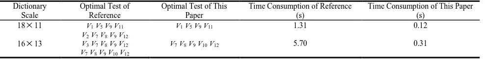
Take a circuit in reference 7 as another instance, whose fault dictionary is indicated by Table 1.
Tab.1The fault dictionary of filter circuit
Fault Test
V1 V2 V3 V4 V5 V6 V7 V8 V9 V10 V11 S0 (no fault) 3 2 2 3 3 3 4 4 1 1 1 S l(R l open circuit) 0 0 0 0 0 0 0 0 1 1 7 S2(R l short circuit) 3 2 2 3 4 3 4 4 1 1 0 S3(R2 open circuit) 1 0 0 0 0 0 0 0 1 1 7 S4(R2 short circuit) 2 3 3 4 6 5 6 6 1 1 2 S5(R3 open circuit) 1 1 1 1 1 1 1 1 1 1 5 S6(R4 open circuit) 0 0 0 2 3 2 3 3 1 1 8 S7(R5 open circuit) 3 2 2 3 5 4 5 5 1 1 4 S8(R5 short circuit) 3 2 2 3 6 6 7 7 1 1 6 S9(R6 open circuit) 3 2 2 3 2 0 0 0 1 1 7 S10(R6 short circuit) 3 2 2 3 3 3 4 2 1 1 4 S11(R7 open circuit) 3 2 2 3 3 2 0 8 5 1 8 S12(R7 short circuit) 3 2 2 3 3 2 2 8 4 1 8 S13(R8 open circuit) 3 2 2 3 3 3 4 4 1 1 0 S14(R9 open circuit) 3 2 2 3 3 3 4 4 2 1 8 S l5(R9 short circuit) 3 2 2 3 3 3 4 4 3 1 8 S]16(R10 open circuit) 3 2 2 3 3 3 4 4 2 2 3 S17(R11 open circuit) 3 2 2 3 3 3 4 4 0 0 1 S18(R12 open circuit) 3 2 2 3 3 3 4 4 1 1 1
The dimension of this fault dictionary M is 16 × 13, and the binary vector represents the column selection of
X = (𝑥1, 𝑥2, … , 𝑥13),M namely the test points. Take EOR operation for every two rows of M to obtain the constraint
matrix A, with the row number of 120 and column number of 13. Substitute the above conditions and go through BAB, and then obtain the solution X = (0, 0, 0, 0, 0, 0, 1, 1, 1, 1, 0, 1, 0), namely the optimal set of test points is [V7,
V8 ,V9 , V10 and V12 ], which is consistent with the conclusion in the references. Table 2 lists the performance
comparison between the method in this paper and that in the references.
Tab.2Performance comparison of test points optimization
Dictionary Scale
Optimal Test of Reference
Optimal Test of This Paper
Time Consumption of Reference (s)
Time Consumption of This Paper (s)
18
11 V1 V5 V9 V11 V1 V5 V9 V11 1.31 0.1216
13V2 V7 V8 V9 V12 V3 V7 V8 V9 V12 V7 V8 V9 V10 V12
V7 V8 V9 V10 V12 5.70 0.31
CONCLUSION
Title
Size Document Number Rev
Date: Sheet of
<Doc> <Rev Code>
<Title>
A
1 1
Wednesday , March 21, 2012
+ 3 -2 V+ 8 V-4 OUT 1 U1A AD746/AD + 5 -6 V+ 8 V-4 OUT 7 U1B AD746/AD + 3 -2 V+ 8 V-4 OUT 1 U2A AD746/AD R2 15k R3 10k R4 6.56k R5 31k R6 31k R7 10k R8 5.56k R9 10k R10 10k R11 10k R12 1k V6 C1 10n C2 10n C3 10n C4 10n V7 V8 V9 V5
0 0 0 0
V1 V2 V4 0 0 V11 V10 V3 V1
FREQ = 1000 VAMPL = 4 VOFF = 0
______________________________________________________________________________
Avionics Lead,1994.
[2] Fijany A, Vatan F. A new method for sensor placement optimization[C].Proceedings of 41st AIAA/ASME/SAE/ASEE Joint Propulsion Conference & Exhibit. Tucson , AZ : AIAA, pp.1-8, 2005.
[3] Worden K, Burrows A P. Engineering Structures, Vol.23(8): pp.885–901,2001.
[4] Yang Shiyuan. Fault Diagnosis of Analog Systems and Reliability Design [M]. Beijing: Tsinghua University Press, 1993.
[5] Starzyk J A, Liu D, Liu Z H, et al. IEEE Transactions on, Vol.53(3) :pp.754-761,2004.
[6] Fijany A, Vatan F. A unified and efficient algorithmic approach to model-based diagnosis and optimal sensor placement[C]. The 8th International Symposium on Artificial Intelligence, Robotics and Automation in Space, Munich : European Space Agency, pp.1-8,2005.