Child Safety Wearable Device
Gopinadh Jonnadula1, Bhanu Prasad Davu2, Hari Kishore Kandula3, Vinod Donepudi4, Sivaiah Etukuri5, 1, 2, 3, 4, 5
Student of ECE, VVIT, Guntur, Andhra Pradesh, India.
Abstract: This project discusses the concept of a smart wearable device for little children. The major pros of this wearable over other wearable is that it can be used in any cellphone and doesn't necessarily require an expensive smartphone and not a very tech savvy individual to operate. The purpose of this device is to help the parents to locate their child with ease. At the moment there are many wearables in the market which help track the daily activity of children and also help find the child using Wi-Fi and Bluetooth services present on the device. But Wi-Fi(Wireless Fidelity) and Bluetooth appear to be an unreliable medium of communication between the parent and child. Therefore, the focus of this project is to have an SMS text enabled communication medium between the child's wearable and the parent as the environment for GSM mobile communication. The parent can send a text as SMS with specific keywords such as “LOCATION”, “TEMPERATURE”, “SOS”, “BUZZ”, etc., to the wearable device. The device will reply back with a text containing the real time accurate location of the child and will also provide the surrounding temperature, so that the parents can keep track if the temperature not suitable for the child. The secondary measure implemented was using a bright SOS Light and distress alarm buzzer present on the wearable device which can be activated by the parents via SMS text to display the SOS signal brightly and sound an alarm which a bystander can instantly react for the child's safety till the parents arrive or they could contact the parents and help locate them. Hence this project aims at providing parents with a sense of security for their child in today's time.
Keywords: Children, Arduino, Safety, Wearble.
I.INTRODUCTION
The motivation for this wearable comes from the increasing need for safety for children in present times as there can be scenarios of the child getting lost in the major crowded areas. This paper focusses on the key aspect that lost children can be helped by the people around the child and can play a significant role in the child's safety until reunited with the parents. Therefore it is intended to use the SMS as the communication type between the parent and child's wearable device, as this has fewer chances of failing when compared to Wi-Fi and Bluetooth. The platform on which this project will be running on is the Arduino Uno microcontroller board based on the ATmega328P, and the functions of sending and receiving SMS, which is provided by the Arduino GSM Module using the GSM network. Also, additional modules employed which will provide the current location of the child to the parents via SMS. The second measure added is SOS Light indicator that will be programmed with Arduino UNO board to display the SOS signal whenever the parent want. In the scenario, a lost child can be located by the parent could send a predefined keyword as an SMS to the wearable device which would reply back by sending location to the parent mobile. Additionally, the wearable equipped with a distress alarm buzzer which sets to active by sending an SMS keyword "BUZZ" to the wearable. Hence the buzzer is louder and can be heard by the parent from very considerable distance. Also the parents via SMS can receive coordinates of the child, which can help them locate the child with maximum accuracy. Some of the existing work done on these similar lines are for example the low-cost, lightweight Wristband Vital which senses and reports hazardous surroundings for people who need immediate assistance such as children and seniors. It is based on a multi-sensor Arduino micro-system and a low power Bluetooth 4.1 module. The major drawback for the Vital band is that it uses Bluetooth as the mode of communication between child and the parent. Therefore, the wearable device proposed will be communicating with the parent via SMS through GSM which would ensure that there is a secure communication link. Also, customization of the wearable can be possible as per our needs by reprogramming the Arduino system.
II.SYSTEM DESIGN AND ARCHITECTURE:
This section discusses the architecture and the design methodologies choosen for the development of the Child Safety wearable device.
A. System Overview
Fig. 1 System overview of the wearable device.
The Fig illustrates the architecture of the child safety wearable device, which depicts the various technologies and technological standards that are used. The Arduino Uno collects the data from the different modules interfaced to it, such as the GPS module upon being triggered by the Arduino Uno by receiving SMS from GSM module. The GSM module is used as an interface to send the data received by the Arduino Uno via SMS to a mobile. The GSM module functions as a trigger for the Arduino Uno to request data from its various modules connected to it. If an SMS text with specified keyword is sent to request the current location or GPS coordinates is sent to the GSM module via the user's phone, then the GSM module triggers the Arduino Uno to request the current GPS coordinates.
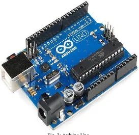
Fig. 2: Arduino Uno
B. Wearable Device
[image:3.612.172.445.379.644.2]Fig3: Proposed Wearable device
The wearable device tasked with acquiring various data from the all the different modules connected to it. It comprises of Arduino Uno based on the ATmega328P microcontroller. The arduino uno receives data from different modules and analysis the data and customises the data in a user understandable format. For the moment the design is not made compact, since the main focus now has been to show that this concept of smart wearables would be highly impactful for the safety of the children. The wearable system runs on a battery or any external source. In order to minimize power consumption, the wearable device has been programmed to provide GPS and other information only upon request by SMS text via GSM.
[image:4.612.37.514.55.349.2]C. Gps location sensor
Fig. 4:GPS Sensor
For determining the real time location of the child NEO6MV2 GPS module has been used which communicates with the Arduino Uno through a 9600 bps software serial interface. The connections between the Arduino Uno and the GPS module established like the connections with GSM module. It has a low power consumption and small size, which is very compact. The GPS module output comprises of standard string information which is governed by the National Marine Electronics Association (NMEA) protocol. Once the SMS trigger text "LOCATION" is sent from the cell phone of the user, this text is received by the GSM which in turn triggers the Arduino Uno to execute the GPS code to fetch the current, accurate location of the GPS module. The location output received from the GPS module is in the following format:
LM35
SOS
BUZZER ARDUINO
UNO GPS
MODULE GSM
Fig 5. Output received GPS location sensor.
The latitude and longitude coordinates received are stored in variables called "latitude" and "longitude," which are then called upon when the SMS text received on the GSM module matches with the keyword "LOCATION". Once the SMS trigger text "LOCATION" is sent from the smartphone of the user, this text is received by the Arduino GSM Shield which in turn triggers the Arduino Uno to execute the GPS code to fetch the current, accurate location of the GPS module. The location output string received from the GPS module is in the following format:
1 220516 Time Stamp 7 173.8 Speed in knots
2 A validity - A-ok, V-invalid 8 231.8 True course
3 5133.82 current Latitude 9 130694 Date Stamp
4 N North/South 10 004.2 Variation
5 00042.24 current Longitude 11 W East/West
6 W East/West 12 *70 checksum
D. Temperature Sensor
Fig. 6:LM35
[image:5.612.51.497.337.673.2]the Arduino uno. The temperature value is stored in a variable which may be integer or string type. Hence the temperature is called by the Arduino upon receiving the proper SMS keyword “TEMPERATURE” by the users smartphone.
Fig 7. Output received from Temperature sensor.
E. Sos light
The another theory that this paper focuses on is that bystanders are the first mode of help for a missing child. The purpose of the SOS light is to be able to alert the people near by that the child might be in distress since the light will be flashing the universal SOS light symbol which may people nowadays know for to be a sign for help. This can be activated by the parent itself by sending an SMS text with the keyword “SOS” to the child’s wearable which will activate the SOS light flashing. The SOS light works on the principal of Morse code in which “S” stands for three short dots and the “O” stands for three long dashes. Since a very long time the SOS signal has been universally known for being the sign of distress and help. The SOS signal is referred to by all security personals, who if find the child to be missing can act and help locate the parents with surplus resources present at their disposal. The SOS light is connected to the pin of the Arduino.
F. Alarm
In the scenario, if a child is saperated from his/her parents. The parent can locate the child by sound in a very loud alarm on the wearable. To achieve this, a piezoelectric buzzer is used, which is responsible for emitting a strong tone upon the output being set to HIGH. The buzzer module is activated upon sending an SMS text with the keyword “BUZZ” from a cell phone. Also, this buzzer works similar to the SOS led by alerting the people nearby with the distressed tone that the child might be lost and is in need of assistance. The buzzer is the child might be lost and is in need of assistance. The buzzer is connected to the digital pin of the arduino.
G. Gateway
1) GSM Module: GSM/GPRS Modem-RS232 is built with Dual Band GSM/GPRS engine- SIM900A, works on frequencies 900/ 1800 MHz. The Modem is coming with RS232 interface, which allows you connect PC as well as microcontroller with RS232 Chip(MAX232). The baud rate is configurable from 9600-115200 through AT command. It is suitable for SMS, Voice as well as DATA transfer application in M2M interface. The onboard Regulated Power supply allows you to connect wide range unregulated power supply . Using this modem, you can make audio calls, SMS, Read SMS, attend the incoming calls and internet ect through simple AT commands.
[image:6.612.238.398.611.717.2]It transfers the information over to the user via SMS. Arduino provides GSM libraries for GSM module as well which allows the GSM module to make/receive a call, send/receive SMS and act as a client/server. The GSM module receives 5V power supply directly from the 5V pin connection at the Arduino Uno 5V. The serial communication between the Arduino Uno and GSM module is performed between the serial pins 0,1. The Arduino has been programmed to receive SMS text messages from the parent’s cellphone via GSM module. The GSM module will constantly be scanning the received text messages for the specific keywords such as “LOCATION”, “TEMPERATURE”, “SOS” and “BUZZ”.
III.RESULTS
In this section, the experimental tests were performed to detennine the various components of the proposed wearable device.
A. GPS Location Sensor
Upon testing the wearable device multiple times with repeated SMS texts. The GPS location sensor was able to respond back with precise latitude and longitude coordinates of the wearable device to the user's cellphone, which then the user would click on the received Google maps URL which would, in tum, open the gmaps app or any default browser and display location
Fig 9. Left: Cellphone SMS app for LOCATION sensor and Right: Google maps with latitude and longitude coordinates displayed.
In all the scenarios the GPS module was tested, it would respond back to the user's cellphone less than a minute. As shown in the image below, the GPS module (red bubble) was able to show the current location of the wearable with pinpoint accuracy and also show exactly at which side of the building it is present. Whereas for blue dot is showing the wearable to be present on the street, which is marginally off from the exact location. This marginal miss match in the pin-point location of the wearable can tum out to be fatal in a real life scenario, where the parent may be miss lead to the wrong location of the child. Therefore, NEO6MV2 GPS module proves to be successful in providing the precise location with high accuracy and with a good response time. The only drawback that could be stated was, the GSM module could not interpret multiple valid keywords sent in a single message. For example, SMS string sent: “LOCATION”,“TEMPERATURE”,“UV”,“BUZZ” AND“SOS” it would not send a reply back to the gsm module.
B. Temperature Sensor
Fig 10. SMS app screen of Temperature sensor
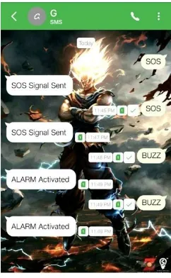
C. SOS Light and Distress Alarm Buzzer
Upon sending an SMS either "SOS" or "BUZZ," this would trigger the light or buzzer to perform an output function instead of providing measurements back to the user's mobile such as in the scenario of the other sensors. Upon receiving the proper keywords, the SOS light and Alarm Buzzer would first perform the particular task of flashing the SOS light and sounding a alarm which can take a little longer than their sensor counterparts.
Fig 11. SMS app screen Top: SOS Light and Bottom: Distress alarm buzzer.
After completion of their respective functions, the response is sent back to the user cell phone stating: "SOS Signal Sent" and "Playing Buzzer".
IV. FUTURE SCOPE
A. Camera Module
and connectivity issues. Therefore, for this project using the GSM technologies is beneficial for us as the cellular range is vast and since all the communication between the wearable and the user is taking place via SMS, therefore no internet connectivity is required. But, still, the GSM module possess the added advantage of using GPRS which enables the board to use the internet if required. Whereas for camera module which supports video streaming but due to the constraint of trying to use only sms, therefore only four wire connections will be taking place. The red and black wires will be connected directly to +5V and GND respectively to the Arduino uno board. Whereas for the RX pin which will be used for sending data via arduino uno and gsm board and for the TX pin which will be utilized for receiving incoming data via from the modules. The lOK resistor divider, the camera's serial data pins are 3.3v logic, and it would be a good idea to divide the 5V down so that its 2.5V.Normally the output from the digital 0 pin is 5V high, the way we connected the resistors is so the camera input (white wire) never goes above 3.3V. To talk to the camera, the Arduino uno will be using two digital pins and a software serial port to communicate to the camera. Since the camera or the Arduino Uno do not have enough onboard memory to save snapshots clicked and store it temporarily, therefore an external storage source microSD board will be used to save the images temporarily. The camera works on a standard baud rate of 38400 baud. The camera will be collecting information in the same manner as the GPS module does. It will be on standby conserving power waiting for the particular keyword "SNAPSHOT" or any other defined in the program to be sent from the user's smartphone to the GSM module will activate the camera by the arduino uno to start clicking a snapshot of the surrounding and save the file temporarily on the external microSD card. After which Arduino Uno will access the saved images from the SD storage and transfer it to the GSM module which send it to the user via SMS/MMS text.
B. Android App
The idea behind the Android app has been derived from having an automated bot to respond to text message responses from the user. It will provide the user with predefined response options at just the click of a button. The user doesn't need to memorize the specific keywords to send. Also, the bot will be pre-programmed to present the user with a set of predefined keyword options such as "LOCATION," "SNAPSHOT," "SOS," etc. Whereas for the future aspect of this wearable device based on what type sensor is added to it, additional specific keywords could be added such as, "HUMIDITY," "ALTITUDE," etc. This android app provides mote interface to the user which help to understand easily. The main idea in this android app is to provide keyword button i.e. that for getting location we have a specific button, by pressing this button we get the location instead of typing the keyword which ease our work.
V. CONCLUSIONS
The child safety wearable device is capable of acting as a smart device. It provides parents with the real-time location, surrounding temperature, SOS light along with Distress alarm buzzer for their child's surroundings and the ability to locate their child or alert bystanders in acting to rescue or comfort the child. The smart child safety wearable can be enhanced much more in the future by using highly compact Arduino modules such as the LilyPad Arduino which can be sewed into fabrics. Also a more power efficient model will have to be created which will be capable of holding the battery for a longer time.
REFERENCES
[1] Akash Moodbidri, Hamid Shahnasser, "Child safety wearable device," in IEEE Xplore , June 2017
[2] B. Dorsemaine, 1. P. Gaulier, 1. P. Wary, N. Kheir and P. Urien, "Internet of Things: A Definition and Taxonomy," Next Generation Mobile Applications, Services and Technologies, 2015 9th International Conference on, Cambridge, 2015, pp. 72- 77.
[3] H. Moustafa, H. Kenn, K. Sayrafian, W. Scanlon and Y. Zhang, "Mobile wearable communications [Guest Editorial]," in IEEE Wireless Communications, vol. 22, no. 1, pp. lO-l1, February 2015
[4] S. Nasrin and P. 1. Radcliffe, "Novel protocol enables DIY home automation," Telecommunication Networks and Applications Conference (ATNAC), 2014 Australasian, Southbank, VIC, 2014, pp. 212-216
[5] F. A. Silva, "Industrial Wireless Sensor Networks: Applications, Protocols, and Standards [Book News]," in IEEE Industrial Electronics Magazine, vol. 8, no. 4, pp. 67-68, Dec. 2014
[6] Jun Zheng; Simplot-Ryl, D.; Bisdikian, c.; Mouftah, H.T., "The internet of things [Guest Editorial]," in Communications Magazine, IEEE , vo1.49, no.ll, pp.30-31, November 2011 doi: 10.1109/MCOM.2011.606970
[7] K. Braam, Tsung-Ching Huang, Chin-Hui Chen, E. Montgomery, S. Vo and R. Beausoleil, "Wristband Vital: A wearable multi-sensor microsystem for real-time assistance via low-power Bluetooth link," Internet of Things (WF-IoT), 2015 IEEE 2nd World Forwn on, Milan, 2015, pp. 87-9l. doi: 10.l109/WF-IoT.2015.7389032
[8] "Digital parenting: The best wearables and new smart baby monitors. The latest smart baby monitors and connected tech for your peace of mind,'Tech. Rep., 2015. [Online]. Available: http://www.wareable.com/parenting/the-best-wearablesbabies-smart-baby-monitors
[10] P. Bhagwat, "Bluetooth: technology for short-range wireless apps," in IEEE Internet Computing, vol. 5, no. 3, pp. 96-103, May/Jun 200l
[11] Y. A. Badamasi, "The working principle of an Arduino," Electronics, Computer and Computation (ICECCO), 2014 11th International Conference on, Abuja, 2014, pp. 1-4
[12] N. N. Prince, "Design and implementation of microcontroller based short message service control system," Internet Technology and Secured Transactions (ICITST), 2013 8th International Conference for, London, 2013, pp. 494-499.