2018 International Conference on Modeling, Simulation and Analysis (ICMSA 2018) ISBN: 978-1-60595-544-5
Numerical Analysis of Working Performance of Pile Group Embedded in
Soft Soil Subjected to Coal Loading
Ai-bin XI
1*, Teng WANG
1, Kun MENG
2, Zhi-meng LIANG
2and Guo-lei XING
11State Nuclear Electric Power Planning, Design & Research Institute, Beijing 100095, China
2Department of Civil Engineering, Dalian Maritime University, Dalian 116026, China
*Corresponding author
Keywords:Soft soil site, Pile group foundation, Coal load.
Abstract. In order to study the mechanical characteristics of pile group foundation in soft soil site
subjected to coal loading, the two-dimensional numerical model of interaction system including pile group and soft soil foundation is established based on ABAQUS program to conduct the numerical analysis of the interaction behavior. Furthermore, the mechanism of internal force and deformation of interaction system of pile group in soft soil foundation is also discussed and some conclusions are drawn which can provide reference for relevant engineering design and practice.
Introduction
With the increasing attention to environmental protection in the modern society, the state has promulgated strict environmental protection policies. More and more large-scale coal storage plants in thermal power plants are totally enclosed type. In order to meet the requirements of coal yard operation and coal storage, the structure of coal storage field needs enough span and height. In addition, in order to meet the requirement of foundation bearing capacity, the group pile foundation form is mostly used for the structure of large span and high coal storage field. The construction of large scale coal yard structure in soft soil field is complicated due to the characteristics of the load and deformation of soft soil pile foundation interaction system and the load form of coal piles and the characteristics of soft soil sites. Therefore, it is of great practical significance and engineering application value to study the stress and deformation characteristics of pile group foundation in soft soil site under the load of pile and coal.
In this respect, many domestic scholars and abroad have done the relevant research. Poulos & Chen [1] (1995) studies the response of group pile foundation under the lateral displacement of soil on the basis of small scale laboratory test. Pan [2] (2002) has carried out a series of model tests to study the pile behavior of the soil under lateral displacement of soil. The results show that the pile bearing capacity is smaller than that of single pile when the pile spacing is 2-5 times, and the group pile effect decreases with the decrease of pile spacing. Li Guo-hao [3] (1981) used the elastic foundation beam method to solve the deformation and internal force of the pile under the vertical load, using the deflection differential equation of the pile. With the continuous development of computer theory and hardware technology, the finite element method is widely applied in pile-soil interaction because it can consider and deal with the influence of various complex boundary conditions, soil deformation characteristics and construction sequence. Pan et al. [4] (2002) adopted Von Mises constitutive relation to simulate the nonlinearity of soil. The three-dimensional finite element model of soft soil site pile foundation interaction system was established, and the stress and deformation characteristics of single pile under horizontal displacement of soil were analyzed. Wu You-xia et al. [5] (2013) made three-dimensional finite element modeling of pile foundation soil, and analyzed the influence of adjacent pile foundation on displacement and deformation under large area surcharge.
contact algorithm is used to describe the contact characteristics of pile-soil interface. The two-dimensional finite element numerical analysis of soft soil site pile group system considering pile soil interaction is carried out under established coal yard loading conditions. The internal force and deformation law of pile group pile in soft soil site under the load of pile and coal is further discussed.
Engineering Situation
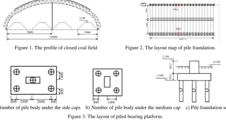
The maximum heap height of the closed strip coal storage field is 12.0m, the closed coal field span is 160m, the longitudinal length is 176m, and the double cylinder net frame structure of bolt ball joints is adopted. The section of a closed coal field is shown in Figure 1. The arrangement of pile foundation in coal storage field is shown in Figure 2. According to the stratigraphic distribution, stratigraphic lithology, depth and physical and mechanical properties of various soil layers and in situ test results, the fourth strong weathered mudstone is identified as the pile end bearing stratum. Specifically, according to the site survey data, the most unfavorable section of the silt soil layer is selected as the most disadvantageous section, and the number of pile body is shown in Figure 3.
The site formation by Quaternary Holocene artificial soil (Q4s), quaternary Holocene marsh
sediments (Q4h), quaternary Holocene alluvium (Q4al+pl) and the three Department of the Pliocene
(N), the main lithology is filled, silt, clay, silt, sand, weathered mudstone, strong weathering powder the sandstone and coal rock composition. The M-C constitutive model is used in the soil around the pile, and the soil parameters are listed in Table 1.
[image:2.595.71.515.364.599.2]
Figure 1. The profile of closed coal field Figure 2. The layout map of pile foundation.
a) Number of pile body under the side caps b) Number of pile body under the medium cap c) Pile foundation section
[image:2.595.75.271.364.447.2]Figure 3. The layout of piled bearing platform.
Table 1. Computational parameters of soil layers.
No. Layer Es
(MPa)
c
(kPa)
φ
(°) v
fpk
(kPa)
1 Plain fill 3.0 18.0 25 0.3 80
2 Silt 1.5 11.5 0 0.3 40
3 Clay 10 30 5 0.3 150
[image:2.595.65.535.621.704.2]Finite Element Model
Parameter Selection
The pile body, the bearing platform and the foundation short column material are C30 concrete, and the linear elastic constitutive model is used. The modulus of elasticity of concrete is 32.5GPa, Poisson's ratio is 0.2, and the density is 2500kg/m3.
The M-C constitutive model was used in the soil around the pile, and the soil parameters were selected according to table 1.
The contact between the pile and the soil around the pile is set up by the penalty function method, and the friction coefficient is 0.3. The soil (more flexible surface) is from the Slave Surface, the pile (the more rigid surface) is the Master surface.
Finite Element Model
Geometric model
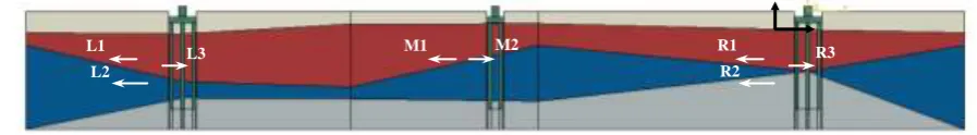
[image:3.595.70.519.330.392.2]The coal yard is a long strip distribution, In the process of modeling, according to the field survey report. According to the stratigraphic information of typical exploration hole points, 40m is taken from the lateral soil of the pile. The bottom of the soil is confined to the vertical and lateral degrees of freedom, and the side of the soil is confined only to the lateral degree of freedom. The pile-soil finite element model and pile number is shown in Figure 4.
Figure 4. 2-D finite element model and pile number.
Initial ground stress field simulation
To obtain an existing initial stress field for the numerical analysis of the site, firstly, the site is calculated under the weight of self weight, and the initial stress field data are obtained. Then the data import model is used to obtain the initial stress field of mutual balance under the action of self weight.
Loading
After balancing the initial ground stress, the load transferred by the superstructure (the vertical load of side piles is 810kN, the lateral force is 520kN, the vertical force of middle piles is 1200kN), and it is applied to the short columns on the basis of the uniformly distributed load. The pile coal load is simplified as trapezoid load according to the actual pile coal curve, and applied to the surface of the soil.
Analysis of Calculation Results
Displacement Analysis of Pile Body
The equivalents of the vertical displacement of the pile are shown in Figure 5. We can see from Figure 5, the left side of the vertical displacement of pile the maximum and minimum values were +83.2mm, -59.1mm, vertical displacement of pile on the right side of the maximum and minimum values were +27.8mm, -21.1mm, the vertical displacement of the pile in the maximum and minimum values were -8.0mm, -9.3mm (with positive and negative displacement modeling coordinate direction, see Figure 4 coordinate). The vertical displacement of the left side pile is significantly higher than that of the middle pile and the right side pile because of the thicker silt soil layer on the left soil.
The horizontal displacement cloud chart of the pile is like Figure 5. From Figure 5, we can see that the positive and negative maximum values of horizontal displacement of the left side piles are +23.2mm and -510.4mm respectively, and the maximum values of lateral displacement of the right side piles are +156.4mm and -3.4mm, respectively. The lateral displacement of middle piles are
L1
L2
L3 M1 M2 R1
R2
+7.1mm and +0.2mm respectively. Due to the thicker silt soil in the left soil, the lateral displacement of the left side pile is caused by the larger soil extrusion. Meanwhile, the soil on both sides of the middle piles is also subjected to the action of coal loading. Most of the compression effect of the left side soil and the right side soil is offset each other, so the lateral displacement amplitude of the middle pile is relatively small.
[image:4.595.168.427.139.266.2]
a) Left side caps b) Right side caps c) Middle caps
Figure 5. Contours of horizontal displacement of piled caps.
Internal Force Analysis of Pile Body
The distribution of the pile shears is shown in Figure 6. From figure 6, we can see that the maximum shear force of the left side piles is 308kN, which occurs on the L3 pile. The maximum value of the shear force on the right side piles is 262kN, which occurs on the R1 pile. The maximum shear force of the middle pile is 212kN, which occurs in the M1 pile. The distribution trend of the shear force along the pile body on the left side piles is consistent with that on the right side piles, and the shear value of the left side piles is slightly larger than the right side piles due to the thicker mud on the left side. The shear force of M1 pile is basically symmetrical, and the shear force of M1 pile is higher than that of M2 pile, which is also due to thicker left muddy soil.
25 20 15 10 5 0
-600 -400 -200 0 200 400 600
Shear force/kN Bur ied d epth/ m L1 L2 L3 25 20 15 10 5 0
-600 -400 -200 0 200 400 600
Shear force/kN Bur ied d epth/ m R1 R2 R3 25 20 15 10 5 0
-600 -400 -200 0 200 400 600
Shear force/kN Bur ied d epth/ m M1 M2
[image:4.595.72.529.423.558.2]a) Left side caps b) Right side caps c) Middle caps
Figure 6. Variations of shearing force of piles with depth.
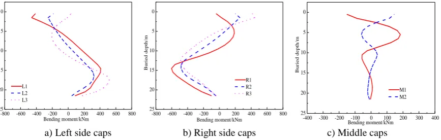
The bending moment distribution of the pile body is shown in Figure 7. From Figure 7, we can see
that the maximum value of the bending moment on the left side piles is 518kNm, which occurs on the L3 pile. The maximum value of the shear force on the right side piles is 603kNm, which occurs on the R1 pile. The maximum shear force of the middle pile is 184kNm, which occurs in the M1 pile.
25 20 15 10 5 0
-800 -600 -400 -200 0 200 400 600 800
Bending moment/kNm Bur ied d epth/ m L1 L2 L3 25 20 15 10 5 0
-800 -600 -400 -200 0 200 400 600 800
Bending moment/kNm Bur ied d epth/ m R1 R2 R3 25 20 15 10 5 0
-400 -300 -200 -100 0 100 200 300 400
Bending moment/kNm Bur ied d epth/ m M1 M2
a)Left side caps b) Right side caps c) Middle caps
[image:4.595.85.519.639.777.2]The stress cloud chart of the pile concrete is shown in Figure 8. From Figure 8 a), it is known that the maximum tensile stress of the left side pile is 5.37MPa, which occurs at the bottom of pile L3 on the side of the heap coal side, and the tension values in the other parts are small. Also, as shown in Figure 8 b), the maximum tensile stress of the right side pile is 6.06MPa, which occurs at the bottom of pile R1 on the side of the heap coal side, and the tensile stress values in other parts are small. The maximum tensile stress of the left side L3 pile and the right side R1 pile all exceed the C30 standard value of the tensile strength of the concrete. Under the load of pile coal, the pile foundation near the pile side will produce larger tensile stress and cause pile failure. From Fig. 8 c), it is known that the maximum tensile stress value of the middle pile is 1.45MPa, which does not exceed the standard value of C30 concrete tensile strength. Therefore, the middle pile is safe under the action of coal loading.
[image:5.595.144.452.223.350.2]
a) Left side caps b) Right side caps c) Middle caps
Figure 8. Stress nephogram of pile.
Conclusion
In this paper, based on the finite element analysis model of soft soil site group pile foundation system under the action of pile load, the force and deformation law of pile group foundation under the established working condition are analyzed. The results of numerical calculation show that:
In soft soil site, when pile load and superstructure load are combined, the lateral displacement of pile group foundation is large (the maximum value is 510.4mm), which can not meet the requirements of pile stability and deformation.
The maximum tensile stress of the left side pile and the right side pile exceeds the standard value of the tensile strength of the concrete. The larger tensile force is enough to cause the concrete cracking and failure of the pile body, which can not meet the requirements of the bearing capacity.
It is suggested that we should further optimize the design scheme of pile foundation, and take appropriate measures for foundation treatment in soft soil site, and calculate and check, so that the interaction system of pile group and soft foundation can meet the requirements of bearing deformation.
References
[1] Poulos H G, Chen L T, Hull T S. Model Tests on Single Piles Subjected to Lateral Soil Movement [J]. Journal of the Japanese Geotechnical Society Soils & Foundation, 1995, 35(4): 85-92.
[2] Pan J L, Goh A T C, Wong K S, et al. Ultimate Soil Pressures for Piles Subjected to Lateral Soil Movements [J]. Journal of Geotechnical & Geoenvironmental Engineering, 2002, 12 8(6):530-535.
[3] Li G H. Study on the theory of bridge and structure [M]. Shang Hai: Shanghai science and Technology Literature Press, 1983.
[4] Pan J L, Goh A T C, Wong K S, et al. Ultimate Soil Pressures for Piles Subjected to Lateral Soil Movements [J]. Journal of Geotechnical & Geoenvironmental Engineering, 2002, 128(6): 530-535.