University of Huddersfield Repository
Simpson, R.M. and McCluskey, T.L.
Plan authoring with continuous effects
Original Citation
Simpson, R.M. and McCluskey, T.L. (2003) Plan authoring with continuous effects. In: PlanSIG
22, 9th/10th Dec 2003, University of Strathclyde, Glasgow. (Unpublished)
This version is available at http://eprints.hud.ac.uk/id/eprint/1637/
The University Repository is a digital collection of the research output of the
University, available on Open Access. Copyright and Moral Rights for the items
on this site are retained by the individual author and/or other copyright owners.
Users may access full items free of charge; copies of full text items generally
can be reproduced, displayed or performed and given to third parties in any
format or medium for personal research or study, educational or notforprofit
purposes without prior permission or charge, provided:
•
The authors, title and full bibliographic details is credited in any copy;
•
A hyperlink and/or URL is included for the original metadata page; and
•
The content is not changed in any way.
For more information, including our policy and submission procedure, please
contact the Repository Team at: [email protected].
Plan Authoring with Continuous Effects R. M. Simpson, T.L.McCluskey Department of Computing Science
University of Huddersfield,Queens Gate,Huddersfield, HD11DH, UK email: [email protected], [email protected]
Abstract
Despite significant success in developing more efficient automated planning algorithms there is a need to widen the scope of the technology to bring it to a wider user community. In this paper we bring together two strands of research both attempting to address the problem of widening the take up of planning technologies. The first strand of research tries to widen the scope by increasing the expressiveness of the representation languages. The second tries to address the problem by enriching and structuring domain modelling languages to support knowledge engineering and to provide rich tool sets to support the creation of domain models. This paper describes ongoing work in developing PDDL+ to more adequately model planning domains where the duration of actions plays a significant role in the planning problem. We have constructed a prototype plan authoring tool to allow the exploration of domains captured in the underlying PDDL+ model of durative actions. The plan authoring tools has been integrated into our GIPO environment [5] and forms both a plan visualisation tool and a plan construction tool.
1
Introduction
1.1
PDDL+ Level 5 Overview
PDDL+ level 5 [1] is the aspirational version of the PDDL language which is designed to cope with real time problem domains involving actions with duration and real valued resources. PDDL+ is designed to allow for the modelling of durative actions where properties of the objects involved are accessible at any point during the execution of an action. This is in contrast to earlier versions of PDDL supporting durative actions where the state of the objects involved were only inspect-able at the end of an action.
From a pragmatic point of view the primary innovation is that structurally the modeller must now describe a planning domain in terms of three constructs. There are actions that bring about instantaneous change to the state of domain objects and may also update the numeric properties of those objects. Actions are the entities that agents must initiate to achieve planning goals. Duration is managed in PDDL Level 5 by the introduction of the notion of a process that is automatically triggered when the domain situation matches some precondition. Processes specify in addition to their start condition how numeric properties of the objects in the domain are updated with the passage of time as a result of the running processes. Processes do not bring about state change of the objects (in the sense of changing the truct value of relations) they only update numeric properties. Processes must be reasoned with by planners but are not directly activated by the agents acting in the domain, despite the fact that the intention behind performing some action may simply be to start a process running. The third element of the level 5 model is the notion of an event which which is automatically triggered as a result of the numeric changes brought about by domain processes. However unlike processes themselves events bring about state change in the objects of the domain and may also update numeric properties of the objects of the domain. Like actions events bring about instantaneous change, but unlike actions events are not directly triggered by the plan executive.
Consider the model of a logistics domain, in which packages are flown from one place to another, and where actions have duration. This might be modelled as a level 5 action of , a process of
and an event of
point the event of arriving would be triggered. The event of arriving would bring about a state change that would result in the termination of the flying process. Termination of the process simply results because the precondition of the process will no longer be true.
1.2
GIPO Tool-set
GIPO is a form of planning CASE tool which helps domain experts to formally capture a definition of their planning domain. It supports the domain expert by providing a semi-graphical approach to domain definition where much of the underlying syntax of the developing specification is taken care of by the tool. GIPO provides the domain developer ways to validate the domain by cross-checking the elements of the specification. GIPO also allows the output of integrated automated planning software to be visualised. It provides manual steppers to allow the domain expert to explore a domain definition to see if it supports known plans to problems within the domain. To enable much of the knowledge engineering tasks to be carried out GIPO uses as its internal modelling language OCL [3] some aspects of which the domain modeller must be aware of to construct a domain specification. However GIPO supports translation from OCL to PDDL hence the usefulness of the tool set is not restricted by the availability of automated planners that work with OCL.
A central tool in GIPO is the Plan Stepper. It assumes a complete (but not necessarily correct) domain def-inition exists and that that specification requires dynamic testing. The stepper allows the user to manually develop a graphical representation of a plan to solve a given domain problem by choosing from the defined operators a sequence in which to apply them and by choosing instantiations of the operator parameters that legally allow the operator’s application at that stage in the developing plan. The tool in addition to providing a graphical representation of the plan checks that each step can be legally applied assuming the given problem’s initial state. In this way the user gains feedback on whether or not the domain specification fulfils his/her expectation. Clearly if the plan is not legal then either the plan itself is flawed or the domain specification is at fault. The user is expected to iterate over this process until both sample plans and domain specification appear satisfactory. The plan stepper allows a user to manually create plan descriptions and have them checked against a developing formal description of the problem domain.
Tools based on the idea of a plan stepper can be of more use than just as a tool for domain model validation. In many domains users are not looking for nor would be prepared to trust fully automated tools to carry out their planning tasks. For such users at least in the short run what they require is more intelligent tools to help them plan [2]. With such problems in mind we propose to leverage the tool set developed for the GIPO environment [5, 6] to provide a set of intelligent plan authoring tools that work at the level of expressiveness of PDDL+. In the short run we see the primary purpose of such tools are that they allow the expressiveness of the Level 5 model to be explored and to investigate additional “knowledge engineering” features that may be added to the language to support the modelling and domain validation processes but ultimately we would hope that such tools could form the basis for a “planner’s spreadsheet” to allow domain experts to explore potential plans within their own domains. Success in the field will ultimately be dependent on the model being able to be used to capture real world problems and on the model still being sufficiently tractable to allow for the creation of efficient automated planners and on tools being available to allow domain models to be constructed and validated and explored in a manner that seems relatively “natural” to domain experts.
1.3
Extending GIPO to deal with the PDDL+ Model
The internal representation language used by GIPO is OCL, and OCL for the hierarchical version. To
the translation in the opposite direction cannot be fully done as OCL+ contains more strutural information about the domain than is present in a PDDL+ specification. The additional information primarily concerns the possible legal states of the object types represented within the domain. In PDDL+ the legal states of objects would have to be inferred from the operator/ process/ event definitions along with the specification of initial and goal states in given problems in the domain.
The feature of GIPO that we have been most interested in extending to deal with this enriched modelling language is the Plan Stepper. This underlies animation tools (to visualise generated plans) and is key to mixed-initiative interaction with a domain expert. The Stepper provides a valuable tool to explore the power of the PDDL+ model; it has the potential to provide a prototype for the equivalent of a planner’s “spreadsheet” allowing the planner within specific application domains to perform “what if” experiments with plans designed to solve the specified problems.
1.4
Visualising Plans
[image:4.612.122.483.425.668.2]How are plans, composed of actions, processes and events, to be visually presented to the user? In the PDDL+ model only “actions” are chosen by the agent or plan author the other elements are automatically triggered when their preconditions are satisfied, but clearly all three elements must be shown to allow a plan to be understood and explored. Using the object centric view adopted in OCL and GIPO, it is natural to show the objects that play a role in the plan and the changes of state that they undergo. To illustrate the interface developed we will refer to the very simple “bath filling” problem described in the PDDL+ manual [1]. In this problem an agent may perform the actions of “putting the plug in the bath” and turning “on” and “off” the hot and cold tap. Turning the taps on adds to the flow of water into the bath and given that the precondition that the plug is in the bath is met and that the flow is greater than zero the process of the bath filling will run. Eventually either the agent must turn the taps off or an event of the bath flooding will occur. In the snapshot of the stepper shown in figure 1 we see the situation after the plug has been put in, the hot tap turned on then after a wait the cold tap turned on and the bath then neglected until it floods. The panes to the left of the window show the initial state of the problem being explored.
In the right split pane we see in the top pane the actions performed shown by coloured spheres, The objects that are referenced in the domain are shown down the left hand side of the pane and spheres occur on the extending line from each object when an action is chosen that affects that object. The name of an action can be seen by hovering the cursor over an action sphere. By right-clicking on an action sphere the details of the instantiated action can be inspected as can the state of the objects referenced in that action. In the same pane as the icons for the chosen actions we can see the flood event represented by a coloured cross with its name visible as the cursor hovers over the icon. Again the details of the action and affected objects can be inspected by right-clicking on the event icon. In the lower split pane we see coloured bars stretched out representing the running processes of the bath filling.
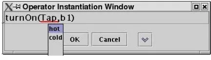
[image:5.612.192.408.263.325.2]The way in which the stepper is used is that the slider at the top of the window represents time and the slider may be dragged to the right to represent the passage of time. As the slider is moved the time line is projected down over the action and process panes. By moving the time line the user selects a time to add an action. The action is added by selecting the action from the drop down box and selecting the “Add Action” button a dialog box then allows the user to select from the available objects how the action definition is to be instantiated. In figure 2 we see the action for turning on a tap being instantiated. The result is then that the
Figure 2: Instantiating an Action
action icons will be placed on the intersections of the primary time line and the individual objects projected time lines. If the action added to the plan triggers any processes then as the time slider is subsequently dragged to the right the process box will extend to the right, in this case representing the filling of the bath. Also as the time slider is moved to the right any events that are triggered as a result of the changes brought about by the active process are displayed automatically and we can see in figure 1 the time line has been extended beyond the point where the flood event has been automatically triggered. At this point the fill process has been terminated as the bath level will no longer increase. Had the domain model been more complex the flood event may, in addition to stopping the filling process have started a new process of the bathroom flooding.
2
An ATC Example
To motivate the following discussion we will introduce a more complex planning domain inspired by air traffic management (the ATC domain). In this domain aircraft have to be tracked and managed as they pass through the air space under consideration. The full OCL+ specification is given in Appendix A.
2.1
Air Traffic Control Domain
The strategy implemented in the ATC domain to manage planes passing through the air space is to assign them to pre-determined flight plans where each flight plan is formed from a sequence of blocks leading from edge to edge of the managed air space. As a plane approaches the air space the controller can assign the plane to a flight plan Block1,Block2,Block3,Block4 or Block5,Block2,Block3,Block4 the plane then
plane’s speed by allowable increments for the plane or to force the plane to circle within a block. The overall goal is to allow planes to pass through the airspace allowing adequate separation between planes. The separation rules are very simply expressed as two planes cannot be in the same block at the same time. A two dimensional version of the airspace is shown in figure 3. In this simplified example if the
Block1
Block2 Block3 Block4
Block5
[image:6.612.194.410.120.201.2]Air Space Layer N
Figure 3: Air Space Segment for ATC Domain
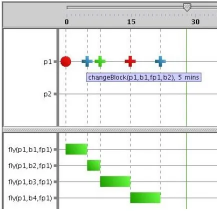
“controller” only has to manage one plane then the only action that needs to be performed is to accept a plane by assigning it to a flight plan. The processes of flying through the sequence of blocks should happen automatically with events firing at each transition. The visualisation provided in GIPO is shown in figure 4. In this snapshot we see the events that have fired at the completion of the plane’s traversal of a block and
Figure 4: A single plane crossing the airspace on Plan 1
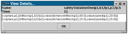
the initiation of a new process to fly across the next block in the flight plan. The final event in the sequence is the traversal of the airspace being completed. A more interesting case shown in figure 5 arises when we have two planes starting the traversal of the airspace at the same time with plane one on flight plan one and plane two on flight plan two. The planes are flying at different speeds and the blocks of air space are of differing sizes. In the final event shown we see that plane two has entered block three before plane one has completed it hence a safety violation event is triggered. At this point all automatic processes are stopped.
[image:6.612.192.409.294.505.2]Figure 5: View of two planes attempting to traverse the Air Space
Figure 6: The state prior to the safety violation firing
2.2
Discussion of ATC Example
The visualisations of the ATC example provides we believe a fairly convincing case to argue that the PDDL+ model coupled with authoring tools has the potential to develop into worthwhile tools to be used beyond the boundaries of the AI Planning community.There are however a number of issues to be raised about the validity of the plans and the strategy used in providing the visualisation in the current implemen-tation.
2.2.1 Continuous Time
The PDDL+ model of time is that it is continuous and is to be modelled by real valued numbers. No specification of the precision of these numbers is given either in the general specification of PDDL+ nor is there any provision for specifying an adequate level of accuracy within individual PDDL+ domains. Fox and Long [1][pp21, 22] in the report on PDDL+ discuss problems arising from the effects on numeric quantities that are dependant on continuous processes. In the following quotation they discuss the strategy of allowing the domain designer to specify a precision to the measurement of time, which would allow in effect the discretisation of time.
[image:7.612.192.414.277.335.2]In GIPO we have adopted the approach involving the ‘discretisation’ of time, and allow the user to deter-mine the units of time to be used. This decision allows a very simple strategy to be used to cycle through the units of passing time updating plan state and firing events as their preconditions are met but we pay the cost of the difficulty described by Fox and Long above. To see how this difficulty arises consider the ATC domain where the granularity of time is set to minutes, if our plane is travelling at 5 miles per minute and an airspace block is 21 miles long then we may not detect that the plane has left the block and started the next until the plane is 4 miles beyond the end of the block. To make matters worse if we record at the time of detecting that the plane has left the block that it starts the next block 0 miles into the block then there will be an accumulating error with each block that has to be traversed. With a flight plan of 10 blocks and an average error of 2.5 miles we will be have an error of 25 miles in the distance travelled when the plane leaves the flight plan which is 5 minutes of travel for our plane so we have not achieved an accuracy of within a minutes error for the entire plan. This problem even manifests itself in the simple “bath” domain where we may fail to detect that the bath level is above the capacity by some gallons of water. In the spirit of the quote above we may want to determine that the flooding occurs at a precise time (not just when the system happens to notice it) and it is that precise time that we need to model. From a philosophical perspective we may reasonably assert that there is a precise time in the world at which time such events occur and that plans need to be valid relative to those precise times. It should not be up to the planning software to determine when such events occur.
In the report on PDDL+ the authors refer to the work of Hezinger who convincingly argues the case that it is not possible to achieve exact precision in the measurement of time or other continuous quantities. If this is correct then our problem becomes one of what level of approximation we can live with and what scope should we give to domain designers to control the degree of approximation acceptable within their domain. The problem is the same regardless of whether we are writing plan generation software or plan validation software: both involve a form of simulation of the world and will only be an approximation to what may actually happen. Though we may always increase the level of accuracy of our simulations we cannot cease to make them approximations. Hence there will always be a potential problem that our software will reject a plan that will work in the world. We could however console ourselves that the plan is not allowing sufficient margin for error to allow it to be rationally chosen.
In GIPO control given is over the granularity of time. This decision allows us to work with a simple model of forward planning to simulate the application of the plan but it does involve the possible rejection of legal plans. In the ATC domain, assume we required that an action of “signing off” had to take place once a plane had completed the flight plan. In the imagined scenario described above (where there are 10 blocks to the airspace) as a result of the accumulated error our simulator would refuse to accept the sign of action as being legal for five minutes after it has in fact become legal with a more accurate mathematical model.
While it is clear that there are strategies that could be adopted to reduce, though not eliminate, such errors it is not clear that we should. It is worth noting that at least some of the problems of accumulated errors can be addressed by the domain designer. The ATC domain definition could be improved by rewriting the specification of the events that record a plane moving from one block to another. The current definition in OCL+ in figure 7 detects when a plane has equalled or gone beyond the length of the block and then starts the plane on the next block at the starting position.
If in contrast we assigned the position in the new block to be the distance beyond the end of the last block flown, as shown in figure 8, we prevent this particular error from accumulating.
2.2.2 Instantaneous Events
event(changeBlock(Plane,Block,Plan,NextBlock), % prevail
[],
% necessary
[sc(plane,Plane,[inBlock(Plane,Block,Plan), nextFlightBlock(Plan,Block,NextBlock),
test(distanceInBlock(Plane) >= blockSize(Block))] =>
[inBlock(Plane,NextBlock,Plan), assign(distanceInBlock(Plane),0.0), assign(speed(Plane),speed(Plane))])], % conditional
[]).
Figure 7: ATC Event to record a Plane Moving to a new Flight Block
event(changeBlock(Plane,Block,Plan,NextBlock), % prevail
[],
% necessary
[sc(plane,Plane,[inBlock(Plane,Block,Plan), nextFlightBlock(Plan,Block,NextBlock),
test(distanceInBlock(Plane) >= blockSize(Block))] =>
[inBlock(Plane,NextBlock,Plan), assign(distanceInBlock(Plane),
(distanceInBlock(Plane)-blockSize(Block))), assign(speed(Plane),speed(Plane))])], % conditional
[]).
Figure 8: ATC Block Change Event to Preserve Distance Travelled
number of them occur at precisely the same instant? If we locate them at a precise time then we need to consider what happens when more than one of these state changes occur at the same instant. If the state changes are both as a result of the application of operators then we can insist, as they are under the control of the planning agent that they do not interfere with one another (as in classical planning). In the PDDL+ manual Fox and Long [1] argue that we accept the same restriction for events and insist that the domain designer does not specify events that are fired in the same situations but have incompatible outcomes. To allow such conflicts would seem to break the deterministic view of our world for our planning perspective. This is in contrast to to the work of Hezinger, which allows for a notion of robust automata that operate with alternative possible transition sequences. Like Fox and Long, we keep to a deterministic assumption for domain models - that the outcome in the world will not be determined by the order in which events fire in the same instant. Unfortunately when we consider the case that an operator and an event both are applied in the same instant we cannot avail ourself of the same solution so easily. This would amount to the requirement that no pair of operator and event share preconditions that can both be met in the same state but where the effects change objects in the domain in incompatible ways. Consider the example of an “alarm clock” whre the agent can turn the alarm on and can turn the alarm off. We might model the alarm clock as having three states “on”, “off” and “ringing”. Turning the alarm on starts a process of the clock counting up to the predetermined alarm time and when this is reached the start ringing event will fire to put the clock into the ringing state. Now what happens if at the instant that the alarm is to go off the agent turns the alarm off? Is the agents action rejected as illegal or is the “start ringing” event overridden? To maintain the deterministic view of the world we either have to require that the domain modeller abandon the obvious encoding of the domain and make sure that actions and events can never interfere or we need to have a conflict resolution policy that planners can reason with.
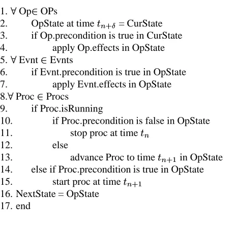
Ad-algorithm Advance State
In OPs : User choosen actions, Evnts : All possible ground events, In Procs : All possible ground processes, CurState : Planning state at time Out NextState : Planning state at time
1. Op! OPs
2. OpState at time #"
= CurState 3. if Op.precondition is true in CurState 4. apply Op.effects in OpState 5. Evnt! Evnts
6. if Evnt.precondition is true in OpState 7. apply Evnt.effects in OpState 8. Proc ! Procs
9. if Proc.isRunning
10. if Proc.precondition is false in OpState 11. stop proc at time
12. else
13. advance Proc to time $
in OpState 14. else if Proc.precondition is true in OpState 15. start proc at time
[image:10.612.90.321.126.347.2]16. NextState = OpState 17. end
Figure 9: An Outline of Advance State Algorithm
vance State algorithm operator application is given priority, and the results of the operators’ application are
assumed available when testing event preconditions. This effectively gives the operators a precedence over the events, although events may fire following the application of the operators to undo their effect. In the “alarm clock” example the effect would be that the alarm would not go off.
2.2.3 Knowledge Engineering Considerations
3
Conclusion and Ongoing Work
In this paper we have introduced a prototype of a plan authoring tool to allow the creation, visualisation and exploration of plans expressed in a model inspired by the PDDL+ definition. Authoring plans in this way highlighted the semantical problems with the language, and we introduced an algorithm to resolve such problems in GIPO. Authoring tools are not new but the focus and motivation for our proposal is different from those of authors such as Jarvis [2]. Our motivation does not come from a wish to develop tools for domains where the nature or complexity of the knowledge takes the application areas a considerable distance away from the sort of domains where the planning problem might be tackled by a fully automated planner. Nor do we wish to provide tools for domains where the risks of plan acceptance are such that human planners are unlikely to cede control to automated planners. Rather our motivation primarily comes from the recognition that for complex domains that can be captured in an application neutral notation, that domain modelling is extremely hard to do. We therefore wish to use aspects of planning technology itself (using for example techiques from machine learning[4]) to make domain definition and maintenance more tractable.
Future work will involve the exploration of more complex domain models and plans using the plan author-ing tool. However, we need to incorporate more tools into GIPO/OCL+ environment, inclusauthor-ing generative planners. We have upgraded some of the editors to manage the new structures required but not yet all, con-sequently OCL+ domain specifications have currently to be partly written in external editors. Similarly the consistency checking between different elements of the specification is currently minimal. Both of these deficits are simply a reflection that this is work in progress and neither pose especially difficult challenges to overcome.
References
[1] M. Fox and D.Long. PDDL2.1: An extension to PDDL for expressing temporal planning domains . In Technical Report, Dept of Computer Science, University of Durham, 2001.
[2] P. Jarvis. Profitable Directions for AI Planning Research. In Proceedings of the AIPS’02 Workshop on
Knowledge Engineering Tools and Techniques for AI Planning, 2002.
[3] D. Liu and T. L. McCluskey. The OCL Language Manual, Version 1.2. Technical report, Department of Computing and Mathematical Sciences, University of Huddersfield , 2000.
[4] T. L. McCluskey, N. E. Richardson, and R. M. Simpson. An Interactive Method for Inducing Operator Descriptions. In The Sixth International Conference on Artificial Intelligence Planning Systems, 2002.
[5] R. M. Simpson and T. L. McCluskey. A Tool Supported Structured Method for Planning Domain Acquisition. In Proceedings of the 13th International Symposium on Methodologies fo r Intelligent
Systems, 2002.
[6] R. M. Simpson, T. L. McCluskey, W. Zhao, R. S. Aylett, and C. Doniat. GIPO: An Integrated Graph-ical Tool to support Knowledge Engineering in AI Planning. In Proceedings of the 6th European
Conference on Planning, 2001.
Appendix
/**
* Automatically generated OCl Domain from GIPO Version 3.0 *
* Author: Ron Simpson
* Date created: Thu Sep 25 08:20:37 BST 2003 * Date last modified: 2003/10/04 at 09:17:22 PM BST * Description:
* This is a simple air traffic control domain. Planes fly through the * area under control on pre determined sequences of blocks.
* The safety rules dictate that no two planes can be in the same * block simultaniously. The controller can starts a plane moving * through the space by accepting the plane on a flight plan. * The controller can then control the flight by
* - slowing the plane
* - speeding the plane up, both by predetermined increments * - ordering the plane to hold (circle) within the current block, * - finally the plane will depart from the managed airspace. */
domain_name(atc).
option(oclPlus).
% Sorts
sorts(primitive_sorts,[plane,block,flightPlan]).
% Objects
objects(plane,[p1,p2]).
objects(block,[b1,b2,b3,b4,b5]). objects(flightPlan,[fp1,fp2]).
% Predicates predicates([ waiting(plane),
holdingInBlock(plane,block,flightPlan), inBlock(plane,block,flightPlan),
departed(plane), inDanger(plane),
nextFlightBlock(flightPlan,block,block), finalBlock(flightPlan,block)]).
% Functors functors([ speed(plane),
distanceInBlock(plane), blockSize(block), maxSpeed(plane), minSpeed(plane),
speedIncrement(plane)]).
% Object Class Definitions substate_classes(plane,Plane,[ [waiting(Plane)],
[departed(Plane)],
[inDanger(Plane),holdingInBlock(Plane,Block,FlightPlan),distanceInBlock(Plane)], [inDanger(Plane),inBlock(Plane,Block,FlightPlan),distanceInBlock(Plane)], [holdingInBlock(Plane,Block,FlightPlan),distanceInBlock(Plane)],
[inBlock(Plane,Block,FlightPlan),distanceInBlock(Plane)]]).
% Atomic Invariants atomic_invariants([
value(blockSize(b1),100.0), value(blockSize(b2),60.0), value(blockSize(b3),130.0), value(blockSize(b4),140.0), value(blockSize(b5),150.0), finalBlock(fp1,b4),
value(minSpeed(p2),10.0), nextFlightBlock(fp1,b1,b2), nextFlightBlock(fp1,b2,b3), nextFlightBlock(fp1,b3,b4), nextFlightBlock(fp2,b5,b2), nextFlightBlock(fp2,b2,b3), nextFlightBlock(fp2,b3,b4), value(speedIncrement(p1),10.0), value(speedIncrement(p2),10.0)]).
% Implied Invariants
% Inconsistent Constraints
% Operators operator(allocate(Plane,Block,Plan), % prevail [], % necessary [sc(plane,Plane,[waiting(Plane)] => [inBlock(Plane,Block,Plan), assign(speed(Plane),speed(Plane)), assign(distanceInBlock(Plane),0.0)])], % conditional []). operator(speedUp(Plane,Block,Plan), % prevail [], % necessary [sc(plane,Plane,[inBlock(Plane,Block,Plan),
test(speed(Plane) <= (maxSpeed(Plane) + speedIncrement(Plane)))] => [inBlock(Plane,Block,Plan), increase(speed(Plane),speedIncrement(Plane)), assign(distanceInBlock(Plane),distanceInBlock(Plane))])], % conditional []). operator(slowDown(Plane,Block,Plan), % prevail [], % necessary [sc(plane,Plane,[inBlock(Plane,Block,Plan),
[], % necessary [sc(plane,Plane,[holdingInBlock(Plane,Block,Plan)] => [inBlock(Plane,Block,Plan), assign(distanceInBlock(Plane),distanceInBlock(Plane)), assign(speed(Plane),speed(Plane))])], % conditional []). % Processes process(fly(Plane,Block,Plan), % prevail [], % update [sc(plane,Plane,[inBlock(Plane,Block,Plan)] =>
[increase(distanceInBlock(Plane),#t * speed(Plane))])]).
% Events event(safetyViolationOne(PlaneA,Block,PlanA,PlaneB,PlanB), % prevail [], % necessary [sc(plane,PlaneA,[inBlock(PlaneA,Block,PlanA), ne(PlaneA,PlaneB)] =>[inDanger(PlaneA)]), sc(plane,PlaneB,[inBlock(PlaneB,Block,PlanB)] =>[inDanger(PlaneB)])], % conditional []). event(changeBlock(Plane,Block,Plan,NextBlock), % prevail [], % necessary [sc(plane,Plane,[inBlock(Plane,Block,Plan), nextFlightBlock(Plan,Block,NextBlock),
test(distanceInBlock(Plane) >= blockSize(Block))] => [inBlock(Plane,NextBlock,Plan), assign(distanceInBlock(Plane),0.0), assign(speed(Plane),speed(Plane))])], % conditional []). event(completeFlight(Plane,Block,Plan), % prevail [], % necessary [sc(plane,Plane,[inBlock(Plane,Block,Plan), finalBlock(Plan,Block),
test(distanceInBlock(Plane) >= blockSize(Block))] =>
[departed(Plane),
assign(distanceInBlock(Plane),0.0)])], % conditional
[]).
% Domain Tasks planner_task(1, % Goals
[
[