Systems Reference Library
IBM 1403 Printer Componant Dascription
Preface
This reference publication for system planners, programmers, and operators describes the functions and operations of the IBM 1403 Printer. Special features available are described; timing information is presented; and print-quality requirements are set forth. The reader should be familiar, within his field of responsibility, with the system to which this printer is attached. For system and programming information, refer to publications listed in the Bibliography for the system.
The manual is sectionalized for convenient access to operating and programming information. Charts throughout the manual provide ready reference for the system planner and programmer.
Ninth Edition (October 1972)
This is a reprint of GA24-3073-7 incorporating changes released in Technical Newsletter GN24-0502, dated September 8, 1972.
Changes are periodically made to the specifications herein; before using this publication in connection with the operation of IBM systems, refer to the latest SRL Newsletter or Bibliography for the editions that are applicable and current:
IBM 1130 IBM 1401/1460 IBM 1410/7010 IBM 1440/1240/1450 IBM 7040/7044 IBM System/3
IBM System/360, System/370 IBM System/360 Model 20
GN20-1130 GA24-1495-6 GA22-6826-5 GA24-3005-6 GN20-7040 GN20-2228 GN20-0360 GN20-0361
Requests for copjes of IBM publications should be made to your IBM representative or to the IBM branch office serving your locality.
IBM 1403 Printer. Introduction
Printing Method, Models 1, 2,4, 5, 6, and 7 Printing Method, Models 3 and N 1 Machine Covers and Safety Operating Information Operator Controls
Printing Controls . Carriage Controls • Indicator Panel Lights Manual Controls . Forms Carriage Control
Control Tape . Acoustical Dampener Metering .
Operator Procedures Print-Quality Requirements Programming Information. Printer Timing
Restart Procedures for 1403 on System/3GO (Models 22 and up) and System/370
Special Features . Numerical Print Preferred Character Set .
Interchangeable Chain Cartridge AdalPter. Universal Character Set •
Multiple Character Set • Auxiliary Ribbon Feeding Selective Tape Listing . Appendix
Extended Binary-Coded Decimal Interchange Code IBM 1403 A and H Print Arrangement.
Index.
Contents
5 5 5 6 6 7 7 7 8 9 · 10 12 · 12 14 · 14 14 18 22 22
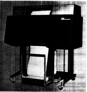
The IBM 1403 Printer (Figure 1) is an output device attachable to many IBM data proc:essing systems. Fanfold paper, preprinted forms, or adding-machine type paper tape may be used. The 1403 can also be used to generate machine-readable input documents for all IBM optical character readers.
A printerts rated speed (Figure 2) is based upon the num-ber of single:-spaced lines that can be printed per minute. Actual printing speed depends also upon the character set used and thc~ time required for processing and for moving paper.
The basic character arrangements for the printers are arrangement A (standard Binary Coded Decimal Interchange Code), or arrangement H (for FORTRAN and COBOL). With either character arrangement, each position can print 48 different characters: 26 alphabetic, 10 numeric, and 12 special characters. A variety of other character sets is available for special applications, predominantly numeric applications, and System/360 installations. See the special
1403 ModEll Print Positions (Lines per minute) Rated Speed
1 100 6000
2 132 6008 i
3z 132 1100n
4L\ 100 465
5L\ 132 465
6 oc L\e 120 340
7 oc'Y 120 600
N1{jz 132 1100n
ex: Single-ClJrriage speed.
{j Appearance significantly different (covers extend to the floor). 'Y Special features limited to: Auxiliary Ribbon and
Interchangeable Curtridge.
6. Not usecl to generate input for 1282 Optical Reader Card Punch.
e Not used to generate input for IBM 1418 and 1428. z Uses 14'16 Interchangeable Train Cartridge.
n Maximum speed: 1400 Ipm with Preferred (Mod 3) or . Universal (Mod 2, 3 and N1) Character Sets.
0 Maximum speed: 1:285 Ipm with Numerical Print Special Feature.
i Maximum speed: 7150 Ipm with Universal Character Set.
Figure 2. Models of the 1403 Printer
IBM 1403 Printer
features section: "Preferred Character Set," "Universal Character Set," and "Multiple Character Set." Most character sets are available in two character sizes: 0.095-in. and 0.079-in. heights (2,41 and 2:,01 mm).
Horizontal spacing is 10 characters per in. (25,4 mm). Standard vertical spacing is six and eight lines per inch, controlled manually by the operator. Vertical spacing and skipping are initiated by the stored program. Standard skipping rate is about 33 in. (83cm) per second. The standard carriage on printers (except Models 6 and 7) used with all systems (except 1401 Model A) is dual speed and permits high-speed skipping at about 75 in.(190 cm) per second on skips of more than eight lines.
The production of machine-readable documents requires attention to print quality and format. The specific require-ments for each optical reader are described in "Print-Quality Requirements" and in manuals for particular optical character readers (see "References-OCR").
Printing Method, Models 1, 2, 4, ~), 6, and 7 The alphabetic, numeric, and special characters are assembled in a chain (Figure 3). As the chain travels in a horizontal plane, each character is printed as it is positioned opposite a magnet-driven hammer that presses the form against the chain.
132 Printing Positions
Paper
Complete Chain Composed of Five 48-Character Sections
Information coming from the processing unit is checked for odd parity. Also, the machine checks to ensure that the hammer is energized for ~he correct print position, that only valid codes are executed, and that overprinting does not occur.
Printing Method, Models 3 and N1
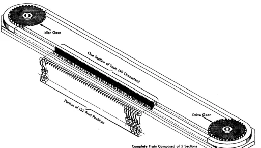
[image:6.623.42.555.403.693.2]The 1403 Printer Models 3 and Nl use a printing system similar to that of the other 1403 models. The system differs in the design of the print slugs and in the method of transport. Instead of a connecting band (chain) of type, the print slugs are assembled in a train, restrained in a track, and driven by a gear to ensure long life at high speeds (Figure 4).
The printing system in the Models 3 and Nl is different from that of the Models 1, 2, 4, 5, 6, and 7. Therefore, do not assume that paper forms and form sets used on the Models 1, 2, 4, 5, 6, and 7 can be used interchangeably on the Models 3 or N 1.
Machine Covers and Safety
The covers of the 1403 are designed to safeguard personnel against possible injury when the machine is in operation.
Figure 4. Schematic of Train Printing Mechanism
Some hazards (such as moving mechanical parts) are obvious; others (such as electrical potentials and acoustical noise) are not.
Although IBM maintains rigorous attention to safety on all its machines, the effectiveness of safeguards is decreased by failure to keep the covers closed when the machine is running.
The frames of all IBM equipment have been made electrically safe by standard grounding practices., The covers are acoustically designed to reduce the noise level below any possible hearing damage. Printer operation with the covers open, however, causes needless exposure to these unseen hazards. Because of this, IBM strongly recommends that all personnel associated with the equip-ment follow the simple safety first procedure of keeping the covers closed whenever the machine is operating. In addition to the safety aspects of this procedure, the visual and aural environment of the installation is significantly enhanced.
If necessary to open the side or rear covers of the 1403 Model Nl, use a coin or a key to operate the metal tab in the vertical gap between the covers.
Note that the motor-driven cover on the 1403 Model Nl rises when a forms error occurs. Therefore, do not place anything on the printer cover.
OPERATOR CONTROLS
The keys and lights (Figures 5 and 6) provide operator control of the printer during setup and programmed interruptions that require operator attention.
Printing Controls
Start
Pressing the start key places the printer in a ready status if the following conditions are met.
Power on
Forms guide plates closed
Feed-clutch control properly positioned Carriag()-control tape installed
Carriag()-brush assembly closed
No error conditions, such as print-check, sync-check, form-check, or end-of-form, exist.
The stalrt key on a 1403 attached to some systems permits operating the printer after the end-of-form light is on, until,channel1 of the carriage tape or on buffer. controlled carriages the first line of the next form is sensed.
A duplicate start key (Figure 7) is located at the rear of the print()r for oper:ator convenience.
Figure S. Operating Keys and Ligh.ts, Models 1 through 7
Operating Information
Figure 6. Operating Keys and Lights, Model Nl
Figure 7. Printer Keys (Rear), Models 1 through 7
[image:7.617.342.583.468.697.2]Check Reset
The check reset key resets a printer error indication. Pressing the start key restarts the operation.
Stop
The stop key stops the printer at the completion of the current operation. A duplicate stop key (Figure 7) is located at the rear of the machine for operator convenience.
Print Ready
The print ready light indicates that the printer has been conditioned by the operator to accept initial instructions and subsequent commands from the system. This light turns off when:
The stop key is pressed The carriage stop key is pressed An end-of-form is indicated
An error condition (such as form-check, sync-check or print-check) occurs.
Print Check
The print check light indicates a malfunction in the printer circuits. The operation may be retried and, if unsuccessful, service may be required.
End of Form
The end-of-form light turns on and the machine stops when an end-of-form condition occurs.
If an end-of-form occurs during a skip or while spacing within the last form in the printer, the operator should single-cycle print until the next skip to a new form occurs. On some systems, the remainder of the last form is completed automatically without stopping. When the last form is skipped out, follow the procedure described for inserting a new form and determining the first print line (see "Forms Insertion").
Form Check
The form check light is turned on for any of the following conditions.
Forms not feeding properly through the forms tractors Forms guide plates open
Carriage-control tape not installed Carriage-brush assembly open
Feed-clutch manual control not properly positioned Carriage stop key pressed.
Sync Check
The sync check light turns on when the chain or train is not in synchronization with the compare circuits for the
printer. The timing is automatically corrected. Pressing the check reset key turns off this light.
A sync check may result if the forms cart is not in contact with the grounding straps attached to the:: base of the machine (not applicable to Model Nl),
Cover Raise, Cover Lower
These keys operate the covers of the Model NI (Figure 6). To raise the cover, press the cover raise key. Holding the key in the operating position is not necessary. To lower the cover, press the cover lower key. If the cover raise key is pressed while the cover is descending, the cover returns to a fully raised_position.
The cover rises automatically when a form check or end-of-form occurs. Therefore, do not place anything on the printer cover (extra forms, card decks, etc.).
Single Cycle
Pressing the single-cycle key operates the printer for one line. Pressing the start key returns the printer to normal continuous operation. If an end-of-form condition exists, single-cycle operation can occur only until channel I of the carriage tape or, on buffer-controlled carriages, until the first line of the next form is sensed.
Note: When the single-cycle key is pressed, control and
diagnostic commands are processed (if issued by the processing unit) until a write command is executed. The printer then enters single-cycle mode.
For further details, check the appropriate system publication.
This key is not installed on 1403 printers attached to a System/360 Model 20, except a 2020 submodel 5 ..
Carriage Controls
Carriage Space
Pressing the carriage space key advances the carriage form one line space if the clutch is engaged. On some systems, this key is operable only when the printer is in a not-ready condition.
Carriage Restore
Pressing the carriage restore key positions the carriage at channell (home position) of the carriage tape, or at line-count I of the forms line line-counter. If the carriage f~eed clutch is disengaged, the form does not move. Modlel NI also has a duplicate carriage restore key located at the rear for operator convenience.
Note: This key must not be pressed when the printer is
Carriage Stop
Pressing the carriage stop key stops the carriage operation and turns on the form check light. The' form may need to be realigned with the program. Press the check reset key to turn off the form (;heck light.
Indicato,r Panel Li~Jhts
This indicator panel (Figure 8), located below the manual feed clutch control, can enable the operator to easily locatt~ and rectify common trouble sources.
Gate Inlk
The gate interlock light indicates that the print unit is not in position. The pri~t-unit release lever locks this unit in position.
Brush Inlk
The brush interlock light indicates that the carriage tape brushes are not latched in position for operation. Shift Inlk
The shift interlock light indicates that the manual feed clutch (;ontrol is not positioned properly.
Figure 8. Indicator Panel
Thermallnlk
The thermal interlock light indicates that a fuse has burned out and that service is required.
HS Start
The high-speed start light indicates that a high-speed skip has been initiated. (This light is not operative on Model 6 and models attached to some systems.)
LS Start
The low-speed start light indkates that a low-speed skip or line spacing has been initiated. (This light is not operative on models attached to some systems.)
HS Stop
The high-speed stop light indicates that a high-speed skip stop has been initiated. The light is also on when the carriage is not in motion. (This light is not operative on Model 6 and models attached to some systems.)
LSStop
The low-speed stop light indicates that a low-speed skip stop has been initiated. The Ught is also on when the carriage is not in motion. (This light is not operative on models attached to some systems.)
Manual Controls
The manual controls are shown in Figures 9 through 13.
Feed Clutch
The feed clutch controls the carriage tape drive and form-feeding mechanism, and selects the 6- or 8-line-per-inch spaciqg. When the feed clutch is set to neutral, automatic form-feeding cannot occur.
Paper Advance
The paper advance knob positions the form vertically. The feed clutch must be disengaged.
Figure 9. Manual Controls, Models 1,2,4,5,6,7
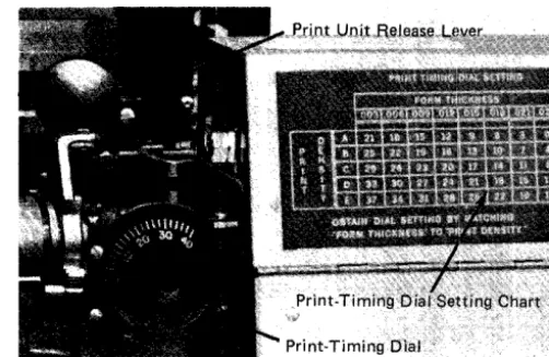
Figure 10. Print-Unit Release Lever (all Models) and Print-Timing Dial, Models 1, 2, 4,5, 6, 7
Vertical Print Adjustment
The vertical print adjustment knob controls the fine spacing adjustment of forms at the print line. The carriage tape is not affected by this adj ustment.
Print-Unit Release
The print-unit release lever unlocks the print unit, allowing it to be swung open to provide access to the form transport area (Figure 10).
Print-Line Indicator and Ribbon Shield
The print-line indicator and ribbon shield (Figure 11) pivot with the ribbon mechanism when the print unit is opened. This assembly may be unlatched from the print unit and pivoted independently.
[image:10.626.298.549.72.235.2] [image:10.626.41.275.258.701.2]Lateral Print Adjustment Lever
This lever allows for horizontal positioning of the printing mechanism. When the lever is raised, the print mechanism unlocks and can be positioned horizontally within its 2.4-in. (61 mm) travel limit. (Models 1,2,4,5,6, and 7 are limited by the positions of the forms tractors.)
Lateral Print Vernier Knob
The lateral print vernier controls the movement of the print mechanism. Movement is up to 1/2 in. (13 mm).
RH Tractor Vernier
The right-hand tractor vernier knob controls fine adjust-ments in paper tension. Lateral movement is up to 1/2 in. (13 mm).
Tractor Slide-Bars
The forms tractors are mounted on two tractor slide-bars, upper and lower. To facilitate positioning the forms tractors, notches are provided in the tractor slide-bar.
The left tractor is locked in place by a spring-loaded latch in one of the nine notches located 1 in. (25,4 mm) apart on the tractor slide-bar.. The third notch from the left end is the normal location for most applications.
The first notch is used for forms from 5-1/2 to 18-3/4 in. (140 to 475 mm) wide. When this notch is used, the lateral movement of the print unit is limited to .4 in. (10 mm). This limitation does not apply to Models 3 and Nl.
The second notch is used for forms from 4-1/2 to 17-3/4 in. (115 to 450 mm) in width. When this notch is used, the lateral movement of the print unit is limited to 1.4 in. (35 mm). This limitation does not apply to Models 3 and Nl.
The third notch is used for forms from 3-1/2 to 16-3/4 in. (90 to 425 mm) wide. When this notch, or one of the notches 4 through 9 is used, a full lateral print-unit move-ment of 2.4 in. (61 mm) is possible.
The ninth (last) notch can be used for forms from 3-1/2 to 10-3/4 in. (90 to 273 mm) wide. When this notch is used, the first print position is No. 38.
The right-hand tractor is locked in place by spring-locked pins snappe,d into anyone of 27 holes, located 1/2 in. (13 mm) apart on the tractor slide-bar.
The movement of the tractor slide-bar is controlled by the right-hand tractor vernier.
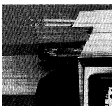
Print-Density Lever
The print-hammer unit accommodates different thicknesses of forms. The print-density lever (Models 1, 2, 4, 5, 6, and 7) provides a vernier control for print impression. When this lever is set at position E, print impression is lightest.
When this lever is set to position A, print impression is darkest. Between these two settings are intermediate settings. Position C is considered the normal setting. This lever moves the type chain closer to, or farther from, the hammer unit (see Figure 9).
Print- Timing Dial
A movable dial (Models 1,2,4,5,6, and 7) is set for fine adjustment of print quality (see Figure 10).
The proper dial setting is obtained from the print-timing dial chart (Figure 10) located Dn the ribbon cover. The setting of the print-density lever, in conjunction with the thickness of the form, gives a nominal setting of the print-timing dial.
The setting from the chart can be adjusted to a finer degree by the operator. For finer setting of the timing dial, turn the timing dial clockwise until the left side of the characters appears to be cut off. Then rotate the dial counterclockwise until the right side of the printing appears to be cut off. The optimum setting of the print-timing dial is halfway between the two readings.
Print-Density Knob
The print-density control on Models 3 and Nl is a knob located on the upper left side of the printer frame (Figure 12). Print density from heavy to light is regulated by settings A to F.
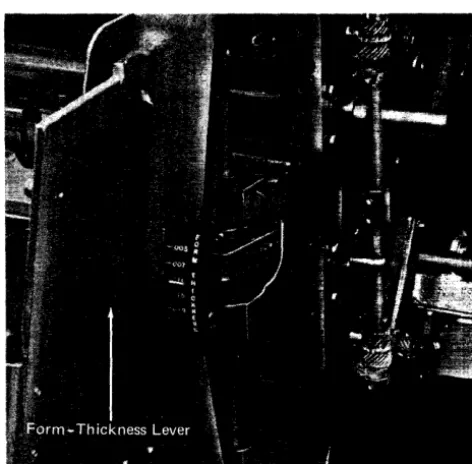
[image:11.621.342.581.461.686.2]Figure 13. Forms-Thickness Lever, Models 3 and Nl
Form- Thickness Lever
The form-thickness lever (Figure 13) on Models 3 and Nl is located at the right-hand end of the ribbon cover (same as the print-density control lever on other models). This lever permits manual adjustment for the various forms (single or multiple copy) thicknesses. The adjustment range is from 0.003 in. (0,08 mm) minimum to 0.019 in. (0,48 mm) maximum graduated in increments of 0.004 in. (0,10 mm).
FORMS CARRIAGE CONTROL
High-speed movement of continuous forms by the carriage is either by tape or by buffer control, depending upon the system to which the 1403 is attached. For tape control, each application has a control tape (Figure 14) corresponding in length to the length of one or more forms. This tape is punched with holes to stop the form when it reaches a predetermined position.
For buffer control, the vertical format for each form is part of the stored program for each application. A standard, prepunched carriage tape, provided with the machine, is used by the program for checking the carriage movement. No operator attention is required other than infrequent inspection for wear of the long-life tape.
With the dual-speed carriage, distances of 8 lines or fewer are skipped at 33 in. (838 mm) per second, and those of more than 8 lines, at 75 in. (1905 mm) per second. The last 8 spaces in a high-speed skip are skipped at 33 in. (838 mm) per second.
[image:12.623.304.542.64.329.2]With the carriage-control tape, the carriage accommodates continuous forms, up to a maximum of 22 in. (559 mm) in
Figure 14. Forms Carriage Control
length (at 6 lines per in.) or 16-1/2 in. (419 mm) in length (at 8 lines per in.). The minimum length is 1 in. (25,4 mm) or 1-1/2 in. (38,1 mm) at 8 or 6 lines per in., respectively.
The buffer-controlled carriage accommodates continuous-forms lengths as defined by the using system. For efficient stacking of forms, the recommended maximum forms length is 17 in. (432 mm). The front door on the Model NI cannot close if forms are over 17 in. (432 mm). The width of the form can vary from a recommended minimum of 3-1/2 in. (89 mm) to a maximum of 18-3/4 in. (476 mm), including punched margins.
Forms can be designed to permit pri.nting in practically any desired arrangement. Skipping to different sections of the form can be controlled by the program in accordance with either the holes punched in the carriage tape or signals from the forms control buffer.
When the paper moves in the carriage for repetItive skipping (using the same channel in the control tape), each skipping operation should be preceded by a command such as WRITE AND SKIP TO CHANNEL X or initiate a spacing operation and then a SKIP TO CHANNEL X. If this is not done, overprinting occurs as the carriage recognizes that it is at channel X or at the defined line count and does not move the carriage.
Control Tape
[image:12.623.42.278.66.298.2]The carriage-control tape (see Figure 14) has 12 columns indicated by vertical lines. These positions are called channels. Holes can be punched in each channel throughout the length of the tape. A maximum of 132 lines can be used to control a form, :although for convenience the tape blanks are slighdy longer. Horizontal lines are spaced six to the in. (25,4 mm) for the entire length of the tape. Round holes in the centl~r of the tape are prepunched for the pin-feed drive that advances the tape in synchronism with the movement of a printed form through the carriage.
Punching the Tapf!
Six-Lines-per-Inch Spacing: A small, compact punch (Figure 15) is provided for punching the tape, The tape is first marked in the channels in which the holes are to be punched. This can be easily done by laying the tape beside the left I~dge of the form it is to control, with the top line (immediately under the glue portion) even with the top edge of the form. Then a mark is made in the first channel, on the line that corresponds to the first printing line of the form. Additional marks are made in the appropriate channels for each of the other skip stops, and for the overflow signal required for the flow.
The marking for one form should be repeated as many times as the length of the tape (22 in. or 559 mm) allows. When the tape controls several forms in one revolution through the sensing mechanism, the life of the tape is increased. Finally, the line corresponding to the bottom edge of the last form should be marked for cutting after the tape: is punched.
The tape is inserted in the punch by placing the line to be punched over the guide line on the base of the punch
Figure llS. Tape Punch
and plaCing the center feed-holes of the tape over the pins projecting from the base. The indicator slide is then moved until the arrow points to the number of the channel to be punched. Pressing on the top of the punch, toward the back, cuts a rectangular hole at the intersection of a vertical and horizontal1ine in the required channel of the tape. The tape should never be punched in more than one channel on the same line. Holes in the same channel should not be spaced closer than eight lines apart. After the tape is punched, it is cut and looped into a belt. The bottom end is glued to the top section marked Glue, with the bottom line coinciding with the first line. Before the tape is glued, the glaze on the tape should be removed with an ink eraser; if this is not done, the tape ends may separate. The center feed-holes should coincide when the two ends of the tape are glued together.
The last hole punched in th(~ tape should be at least four lines from the cut edge, because apprOximately the last half in. (12,7 mm) of the tape overlaps the glue section when the two ends are spliced. If a hole must be punched lower than four lines from the bottom of the form, place the tape with the top line (immediately under the glue portion) four lines lower than the top edge of the form, before marking the channels. To compensate for the loss, cut the tape four lines lower than the bottom edge of the form.
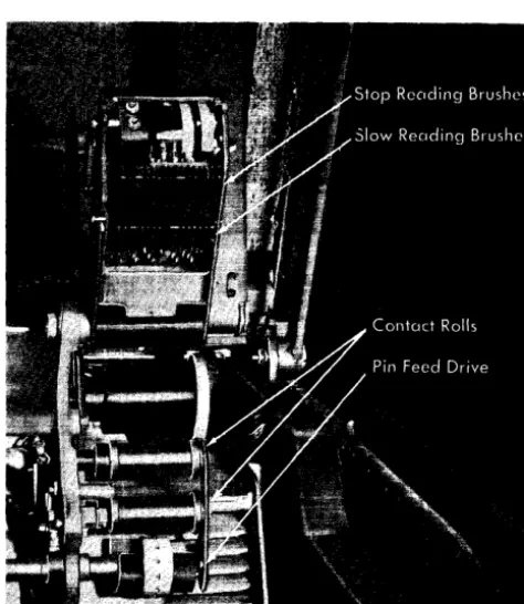
Carriage- Tape Brushes
Two sets of reading brushes (Figure 16) mounted on the same frame sense holes in the carriage-control tape. A small contact roll is used for each set of brushes. One set is called
the slow brushes. The other set is called the stop brushes.
Seven spaces, as measured by the control tape, separate the brush sets. The slow brushes are positioned ahead of the stop brushes.
The slow brushes control high-speed skipping. They regulate the speed of the last eight spaces of a high-speed skip. (Single-speed carriages do not have the slow brushes.)
All carriage stop brushes can function to stop a carriage skip under control of the stored program.
ACOUSTICAL DAMPENER
The acoustical dampener on Models 1,2,4,5,6, and 7 is a nylon and bronze brush on the print-unit frame. The dampener provides a drag on single-part forms to dampen high-frequency vibration of the paper. The brush is hinged so that it can be rotated out of the way when not needed. To prevent damage to single-part forms, rotate the brush away from the paper when the print unit is moved horizontally for alignment.
[image:14.624.39.276.430.703.2]On Model 3, the acoustical dampeners consist of electro-magnetic plates located below the hammer unit. The plates, energized momentarily during printing, grip the forms and block the passage of an acoustical wave down the paper.
Figure 16. Carriage-Tape Brushes
METERING
The meter on the 1403 is activated when the program nrst calls upon the printer. The meter stops when th(~ system meter stops. Intermediate starts and stops may occur (for instance, whenever the printer requires operator attention and is not ready), but these depend on the particular system to which the printer is attached. For metering operation on a particular system, refer to the appropriate System Reference Library. See the list of publications under "Programming Information."
OPERATOR PROCEDURES
Carriage-Tape Insertion
1. Raise the printer cover.
2. Turn the feed clutch to neutral.
3. Press the latch on the side of the brush holder, and raise the assembly.
4. With the printing on the outside of the tape loop, place the loop over the pin-feed drive wheel so that the pins engage the holes in the tape. Be certain that the line-position numbers are on the right side of the tape loop, as seen from the front of the printer.
5. Place the other end of the loop around the adjustable carriage-control tape idler.
6. Adjust the idler by loosening the locking knob and moving the idler in its track. No noticeable slack should be in the tape, but the tape should not be under tension. Test the tape by pressing the sides of the loop together. There should be some give. If the tape is too tight, the pin-feed holes will be damaged. Be sure to retighten the locking knob on the idler.
7. Lower the brush assembly. A click can be heard when the latch engages.
8. Press the restore key. When the tape has returned to the home (channel-lor line-count 1) position, engage the feed clutch.
9. Close the printer cover.
Ribbon Changing
To change the ribbon (Figure 17) on the 1403 Printer: 1. Raise the printer cover.
2. Pull back and unlock the print unit release lever. Swing out the print unit.
3. Open the top ribbon cover.
4. Unlatch the print-line indicator ribbon shield and swing it away from the ribbon, against the forms area ..
Figure 17. Ribbon Mechanism
6. On printers without the auxiliary ribbon feeding, slip the ri.bbon from under the ribbon correction roller. 7. To remove the bottom rolt. press the ribbon roll to the
right:. lower the left end of the ribbon roll, and remove it from the mechanism.
8. When replacing the ribbon in the machine, hand-tighten the ribbon to remove slack from in front of the printing mechanism.
Ribbons are available in II-in. (279,4 mm) widths, in addition to the standard 14-in. (355,6 mm). The ribbon-width lever (Figure 18) can adjust the ribbon-feed mechanism to accommodate the various ribbon widths.
Note: When installing a new ribbon in the printer, always
load the full ribbon spool on the bottom spindle to assure proper ribbon skew on the first winding of the ribbon (Figure 19).
Forms IlI1sertion
1. Raise the front cover of the printer to gain access to the print unit and forms area.
Figure 18. Front of Printer (Cover Raised)
Print Chain Ribbon S h l e l d - (
Figure 19. Installing a New Ribbon
2. Turn the feed clutch to NEUTRAL.
Ribbon-Reversing Bars
3. Unlock and swing back the print unit by pulling the print-unit release lever toward you.
4. Set both the left-hand fOIms tractors slightly to the left of the first printing position. Pull the tractor until it latches in the appropria.te notch (Figure 20). 5. Open the left-hand tractor covers and place the forms
over the pins. Close the covers. 6. Open both right-hand tractor covers.
7. Move the right-hand tractors to the desired location to line up the right side of the forms. Pull out the tractor pin-latch, and slide the tractor until the pin snaps into the appropriate position (see Figure 11).
8. Place the forms over the tractor feed-pins and close the tractor covers.
9. Tighten the tension on the form, using the right-hand tractor vernier.
10. To position the form, turn the paper advance knob until the block, line, or area on which the first line of print is to occur is just visible above the ribbon guide bar (except Models 3 and N 1). Align the desired hammer position to the form with the lateral
print-Figure 20. Forms Tractors, Mode:ls 1,2,4,5,6,7
[image:15.613.309.583.497.697.2]alignment lever and vernier. Observe the relationship to the form of the markings on the ribbon guide-bar. Now, turn the paper advance knob backward three line spaces (if in six-line neutral, or four line spaces if in eight-line neutral). The form is now properly positioned.
Note: If your printer is a Model 3 or Nl , turn the paper
advance knob backward 4 line spaces for 6-line operation and 5 line spaces for 8-line operation. These models have a plastic ribbon shield that is one line-space higher than the ribbon shields of other models of the 1403 printer. The top surface of the extreme left and right ends of the plastic ribbon shield may still be used for vertical forms alignment when the ribbon shield is unlatched from the print unit and swung against the forms.
11. Close and lock the print unit. Be sure to push the print-unit release lever as far back as it can go.
12. Restore the carriage tape to the first printing position (or the forms-control buffer to line-count 1) by pressing the carriage restore button.
13. Set the feed clutch to DRIVE. Set it for either six or eight lines per in. (25,4 mm), depending on the form to be printed.
14. Close the cover of the printer.
15. Position the paper supply on the input-paper cart so that the forms feed straight up into the machine. 16. When printing begins, operator attention is required
behind the printer. The first form must be guided between the forms stacker-guide and the machine. Then, the first forms must be adjusted in the stacker so they fold flatly. See "Forms Stacking."
Interchangeable Cartridge Changing
To change the cartridge (for chain printers used with the Interchangeable Chain Cartridge special feature or any train-cartridge printer):
1. Raise the printer cover.
2. Pull back and unlock the p!int-unit release lever. Swing out the print unit.
3. Open the top ribbon cover.
4. Unlatch the print-line indicator and swing it against the form.
5. Remove the top ribbon spool as described under "Ribbon Changing," and place it on the tray at the bottom of the print unit.
6. Pivot the two handles on top of the cartridge to their vertical position. The cartridge is unlocked and may be lifted free of the print unit by the handles (Figure 21). For Models 3 and Nl, go to step 10.
7. Lift the chain cartridge with the handles and lower it evenly into position on the aligning pins.
8. If the left end of the cartridge does not seat fully (aligning pins flush with top of cartridge):
Figure 21. Interchangeable Train Cartridge, Models 3 and N1.
a. Manually rotate the chain counterclockwise while pressing the idler gear brake button in the chain drive gear cover.
b. Align the driving key in the timing disk with the slot in the chain drive sprocket.
9. Press down lightly on the handles to lock the cartridge in position. If the cartridge does not lock, do not force. Repeat step 8.
For Models 1,2,4,5, and 7, go to step 14.
10. Using the special tool attached to the printer, turn the notched driver on the right side of the print unit until a screw is visible in the nearby open hole in the cover plate. If any further adjustment is required to align the notch in the driver with the notch in the casting, complete this alignment. This final adjustment is minor if the screw is properly positioned.
11. With the same tool, turn the driven gear in the new cartridge until the appropriate character on the specially marked slug is in line with the arrow engraved on the cartridge base. On standard cartridges, the proper character is the digit 1 on the marked type slug. If the standard cartridge has no marked slug, align any digit 1 wi th the arrow.
12. Place the cartridge on its locating pins in the print unit. 13. Lock the cartridge in place by pivoting the handles down
to their horizontal (original) position. 14. Replace the ribbon spool.
15. Close and lock the print unit. 16. Lower the cover.
Forms Stacking
print area, over the top of the printer, and downward into the stacker at the back of the machine. Here the forms are refolded into a flat stack.
As the forms enter the stacker, they pass between the powered stacker rolls and a paper-tension device. This device varies in physical appearance anq construction according to the printer model. On Models 3 and Nl, it consists of a set of idler rolls; on all other models, it consists of a set of circular flat springs. In either case, the operator can disengage the d.evice from the stacker rolls to permit gravity stacking.
The paper-guide arrangement also varies with the printer model. In all cases it is used to help stack the paper evenly. Satisfactory stacking under power depends on the care with which the operator positions or adjusts and supervises the operation of the forms-feeding and stacking mechanisms.
Among the common operator actions recommended for good forms-feeding and stacking are the following. 1. Remove the blank forms from their shipping cartons
before installing them in the printer. Air suction produced as th(~ forms are pulled from the carton increases the drag on the paper sufficiently to tear or distort the pin-feed holes at the edges of the forms.
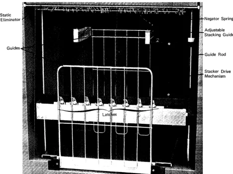
Static Eliminator
[image:17.617.86.554.353.703.2]Guides
Figure 22. Forms Stacker, Model N1
2. Be careful when adjusting the forms tractors. Never adjust the horizontal tractor vernier so that the form is stretched too tightly. This can tear or distort the pin-feed holes in the forms.
In addition, the following operating procedures (according to the printer model) are recommended.
For the 1403 Model Nl: position the adjustable stacking guide and the hinged forms guide (Figure 22) to center the stack of printed forms directly beneath the stacker rolls. The adjustable stacking guide can be shifted from front to back by engaging it in the correct holding slots at the top. The hinged forms guide can be adjusted from front to back by sliding the paper tray in or out as required. Of course, this guide must be in the raised position during stacking. For Models 3 and Nl:
1. Starting at each edge of the form and progressing toward the center, engage with the: stacker rolls only as many paper-tension idler rolls (Figure 22) as are required to pull the forms smoothly from the printer into the stacker. This applies particularly to multiple-part forms. 2. Initially set the stacker roUs about five in. (l27 mm)
above the top of the stack" Reposition them whenever
Negator Spring
Adjustable Stacking Guide
Guide Rod
this distance becomes less than two in. (51 mm). For heavy forms, and for light forms having no skips over five in. (127 mm), this distance may be increased beyond five inches (127 mm).
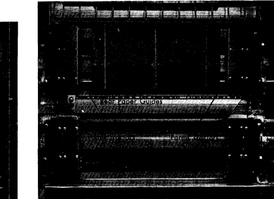
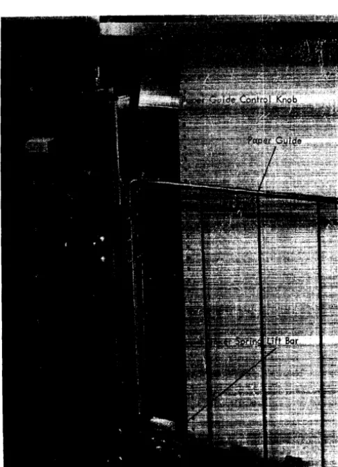
3. Occasionally dress down the stack, pressing on the paper to squeeze out trapped air and maintain a flat stack. For all other 1403 models: position the sliding paper guide (Figure 23) up or down as required to obtain the best folding and stacking condition. Use the paper-guide control knob to raise or lower the paper guide. This knob slides along a printed scale graduated from 0 through 6 for convenient operator reference. The lower edge of the paper guide assists in folding the paper; thus, as the pile of stacked forms rises, raise the guide correspondingly.
[image:18.623.38.281.363.699.2]Gravity stacking is obtained by disengaging the paper-tension device from the powered stacker rolls. In Models 3 and Nl, the idler rolls can be individually latched in the disengaged position. In all the other 1403 models, use the stacker spring lift bar (refer to Figure 23) to move the circular tension springs away from the stacker rolls.
Figure 23. Forms Stacker, Models 1 through 7
Stacking Improvement Device
The 1403 Model Nl i:; equipped with the stacking improve. ment device. This device improves forms stacking when repeated long skips occur.
Stacker rolls in the Model Nl turn at a constant speed. The speed is fixed at a rate that gives the best stacking conditions for the majority of printing applications. With the stacker rolls turning at a fixed rate of speed, however, repeated long skips allow the carriage to eject forms faster than the stacker rolls can take them up. This results in an accumulation of forms at the top of the printer. The stacking improvement device prevents this accumulation from becoming excessive by allowing the stacker time to recover from this backlog of forms.
Circuitry in this device calculates the ratio of paper ejected to paper stacked. When this ratio reaches a pre-determined value, the circuitry cuts off the high-speed drive to the carriage for the remainder of the skip being executed. This skip continues, uninterrupted, at low speed.
During the next print operation, some, if not all, of the accumulated forms are stacked. This reduces the forms accumulation sufficiently to ensure that the next skip operation always starts in high speed.
Operation of this device is completely automatic. It depends entirely upon the program being executed and the length of the forms being used. For example:
1. A single line of printing allows enough time to stack the amount of paper accumulated during 12 lines of high-speed skipping.
2. If six or more lines print on any form up to 22 in. (558,8 mm) long, the device remains inoperative.
3. Repeated long skips after printing three or fewer lines represent about the only time this device becomes active. 4. With a pattern of repeated long skips after three or
fewer lines of printing, about four forms-lengths are required to activate the device. The device then remains active as long as these conditions exist.
5. In most cases, the net acceptable throughput actually increases due to the reduction in required operator attention.
Figure 24 shows the time lost per form, in milliseconds, when the stacking improvement device is active.
PRINT-QUALITY REOUIREMENTS
When the 1403 printer is used in optical character recog-nition (OCR) applications, or when the ALA train cartridge is used in particular library applications, correct machine setup is important. The operator must take certain precautions to ensure acceptable print quality. Th(lse include:
Form Length
3-% inches (8S,9mm), (or less) 7 inches (177,Smm)
S-% inches (215,9mm) 11 inches (279,4mm) 14 inches (3£i5,6mm) 17 inches (4:n,S mm) 22 inches (5f;S,Smm)
Lines Printed per Form 6 or 1 2 3 4 5 More 0 0 0 0 0 30 0 0 0 0 60 5 0 0 0 95 45 0 0 0 140 90 35 0 0 160 110 55' 5 0 260 205 155 105 50 Figures represent approximate time lost in milliseconds per
0 0 0 0 0 0 0
form when Stacking Improvement Device is operating continuously in a steady state.
Figure 24. Stacking Improvement Device Reference Chart
2. Supervising and adjusting the print density as required. 3. Replacing the ribbon as required.
4. Cleaning the type faces.
Ribbons and Paper
For applications in which OCR is used extensively, the IBM OCR ribbon (part 414486) or equivalent, is recommended. For less extensive OCR applications on the 1403 Model 2 only, the IBM general-purpose ribbon (part 419098), or equivalent, may be used, provided a 20- to 24-pound (75-to 90-gram per square meter) bond paper is used. Other weights of paper require the IBM OCR ribbon, or equivalent.
With the ALA train, optimum print quality can be obtained by using the IBM polyester ribbon (part 424325 or 1136917), or equivalent, and single-part, continuous-form, offset. master paper or 20- to 24-pound (75- to 90-gram pel' square meter) bond paper. The quality of the paper, number of parts of the form, and coarseness of the ribbon affect the distinctness of the diacritical marks.
Because of possible overlap of these special symbols, printing eight lines per inch is not recommended. The following items should be tested to assure acceptable results: other ribbons, other paper, continuous card forms, line spacing closer than six lines per inch, and special duplicating applications such as spirit, photo-offset, multilith, diazo, heat transfer, or similar processes.
Ribbon Life
Ribbon life depends upon the amount of ribbon usage. Because new ribbons contain more: ink than used ones, the initial print density (darkness of impression) is heavy. The more the ribbon is used, the less ink it contains and the lighter the print density becomes. Therefore, the operator should check the print density at the beginning of the job and periodically throughout the run, and adjust the print-density control as required to maintain the best print 'quality. See "Print-Density Adjustment."
When printing becomes so light that further adjustment of the print-density control produces no appreciable improvement, replace the ribbon. See "Ribbon Changing." When an OCR ribbon is used, the condition does not occur usually until 250,000 lines have been printed.
Figures 25 and 26 illustrate acceptable and unacceptable OCR printing related to ribbon life. Lines one and two show acceptable printing, and lines three and four show marginal printing. Lines five and six represent unacceptable printing: both inadequate ink coverage and insufficient stroke width.
Character-Stroke Width
Except for the period or decimal, and comma, the character-stroke width for OCR should measure 0.010-0.018 in. (0,25-0,46 mm). The samples of printing shown in this publication can be used for visual comparison. These samples show accept-able as well as unacceptaccept-able stroke widths.
{
0)
005-6-5--4-3-2-1-0-0-9-8-7030200016329Acceptable
®
777879707-780087-70797877767574737271{
(2)
0050-00090807060504030201030200042996Marginal.
CD
0078-808988878685848382 B 1030200052419f
CD
4 rJ 4 0't - '. [\
(1/t - 4 ()'i
9'. q't
7 46 4 '.) " '. 4 3 '. ? 4 1 - 02 5 12u nacceptab h~ )
~
CD _.
9 -n - :) -
C' 0 - IJ - 0- 9 - ,8 - 7 - 6 - :"- '{ -3 -
? - 1 .-2 7 5 2 BHNHMHLHKHJHIHHHGHFHEHDHCH8HAHH 2S3011gS8
Acceptable
KNKMKLKKKJK"JKHKGKfKEKDKCKBKAKK
263020261
{ CD
XNXMXLXKXJXIXHXG~fXEXDXCX8XAXX 26JC]252~
Marginal
~
~
0
UNUIVIULUJ<UJU I UHUGUfU[UDUCU8UAUU26JO~137.l.
(G0
2N2M2l2K2J212H2G2F2E2D2C282A22
253uS3~29
Unacceptable)
t
G0123~S67b9C12J4567d90123~567090 2S3[S~LOO
Figure 26. Ribbon Life Related to OCR Print Quality (1428 Font)
Figure 27 shows two samples of ideal OCR printing with stroke widths of 0.013 in. (0,33 mm) and 0.011 in. (0,28 mm). A sample with stroke widths of 0.008 in. (0,20 mm) is included for comparison.
Print-Density and Forms-Thickness Adjustments
In applications in which print quality is critical, correct print-density and forms-thickness adjustments are important. The forms-thickness adjustment must correspond to the thickness of the forms used. If this thickness cannot be measured directly, secure this information from the paper supplier. The thickness of 20- to 24-pound (75- to 90-gram per square meter) paper is about 0.004 in. (0,10 mm), and continuous-forms card stock is about 0.007 in. (0,18 mm). The continuous-forms tractors should be adjusted to hold the forms as taut as possible without bursting or tearing the forms.
Because each printing format causes unique ribbon wear, the operator must experiment with a print-density adjust-ment schedule that provides optimum results for his particular application. A good quality OCR ribbon has a usage expectancy (for OCR printing) of 250,000 lines. As a starting point, the following schedule of print-density settings for the degree of ribbon wear is recommended:
Ribbon Usag2
New to 50,000 lines 50,000 to 100,000 lines 100,000 to 150,000 lines 150,000 to 250,000 lines
Print-Density Setting
D
C
B
A
1234567890-0
0.013 in. (0,32 mm) Stroke Width1 23456 7 8 90 -
C 0.011 in. (0,2Smm) Stroke Width123456 7 8 9 0-C O.OOS. in. (0,20 mm) Stroke Width
Figure 27. Stroke-Width Variations
Figure 28 shows print-density conditions (enlarged) that can be corrected by the 1403 operator. The method of obtaining print-density variations differs between the 1403 chain and train printers.
Chain Printers: On all 1403 models except Modlels 3 and
Nl, adjust the print-density control lever (see Figure 9) to get the best impression with the thickness of the forms being used. Then set the print-timing dial (see Figure 10) for that thickness, as prescribed by the chart on the print unit (also in Figure 10). If the left edges of the characters are cut off, turn the print-timing dial counterclockwise until they reappear. If the right edges are cut off, turn the dial clockwise. (Refer to Figure 28A and B.)
Train Printers: On 1403 Models 3 and Nl, set the
forms-thickness lever to correspond with the forms-thickness of the forms being used. Then set the print-density control knob for the best impression. If the tops of the characters are lighter than the bottoms, increase the setting of the forms-thickness lever. If the bottoms are lighter than the tops,
HHHH
HHHH
HHHH
HHHH
HHHH
Cutoff (Left)
Cutoff (R ight)
Light Bottoms
Light Tops
Slur (Excessive Width of Vertical Strokes)
A
B
C
D
E
[image:20.617.306.458.529.697.2]reduce the forms-thickness setting. (Refer to Figure 28C and D.) Reducing the print density can help eliminate a slur (Figure 28E). This is especially significant during early ribbon life.,
If these a.djustments do not satisfactorily correct the conditions required for acceptable print quality, notify a service representative.
Print-Quality Test Pmcedure
To detect a maladjustment that affects print quality and to find the optimum print-density setting, perform the following procedure periodically before actually printing documents, to be used for optical character reading. 1. Install ribbon to be used.
2. Insert documents in the forms-feeding mechanism and set the lPrinter controls for the thickness of the document. 3. With the print-density control set at E, print a few lines
of H's in all positions to check for fading across the print line (characters blacker on one side of the form than those on the other side). If fading occurs, notify a service representative.
4. With the print-density control set at D, continue printing and look for conditions shown in Figure 28.
5. Vary the print-density control through several positions to determine the optimum setting for the actual printing of documents. At different impression levels, observe the printing for light density, stroke sections, extraneous ink, and excessive stroke widths.
Type-Face Cleaning
For best n~sults, the operator should periodically clean the type faces, first with a vacuum cleaner, then with type-cleaning paper (IBM part 451529, or equivalent). This is a crepe-like paper having a tacky surface. As the hammers drive the cleaning paper against the type (ribbon removed) dirt from the type adheres to its surface. Only one or two sheets are required to clean all the type. Discard the dirty sheets.
Note: Under no circumstances should the operator attempt to clean the chain or train by any method other than the following.
Chain Printers: To clean the 1403 chain printers (all models except 3 and N 1 ) :
1. Open th.e print unit and remove the ribbon.
2. Vacuum-clean the cartridge, type faces, and print area. 3. Install the type-c1eaning paper on the tractors,just like
any other form. Be sure the crepe side is facing you.
4. PosItion the paper and trac:tors so that the entire print line is between the perforated margins.
5. Close and lock the print unit.
6. Set the density control lever to C, and the print-timing dial to 17.
7. Put the carriage drive in neutral and press CHECK RESET. (This turns off the forms-check light.)
8. Leave the top cover open and load a suitable program such as OLTEP (On-Line Test Executive Program-available from IBM); press START. The machine starts printing a ripple pattern designed to print every charac-ter in every print position many times.
For printers having UCS, use OLTEP program T-1403M; for printers without UCS, use OLTEP program T-1403N. The OLTEP programs are preferred. If these are not available, however, any customer program that exercises the printer may be used.
9. Using the paper advance knob (see Figure 9), manually space the paper every five or six lines while printing until the type faces are clean, as indicated by a light printed line.
Avoid printing more than ten print lines on the same space as this tends to shred the crepe surface of the paper. The shreds that flake off may lodge between the type slugs and damage the chain or train.
10. Remove and discard the dirty cleaning paper. Reinstall the ribbon.
Train Printers: To clean the 1403 train printers (Models 3 and Nl), follow the procedures enumerated under "Chain Printers" in this section, except substitute the following for step 6.
6. Set the print-density control knob to C, and the forms-thickness lever to 0.015 inch. (0,38 mm).
References-OCR
For additional information, the operator should refer to the following manuals:
IBM 1231 and 1232 Optical Mark Page Readers, GA21-9012 IBM 1282 Optical Reader Card Punch, GA24-3106 IBM 1287 Optical Reader, GA21-9064
IBM 1288 Optical Page Reader, GA21-9081
IBM 1418 Optical Character Reader, IBM 1428 Alphameric Optical Reader, GA24-1473
Print Quality Considerations, IBM 1418 and IBM 1428, GA24-1452
Programming Information
For the information required by the programmer about the 1403 Printer, see the publications listed by system below.
System(s)
1401 (except Model G) and 1460
1401G
1410
1440
7010
7040 and 7044
System/3
System/360 Model 20
System/360 Model 22 and up
System/370
PRINTER TIMING
Publication
System Operation Reference Manual, IBM 1401 Data Processing System, IBM 1460 Data Processing System, GA24-3067
IBM 1401G System Summary,
GA24-3165
IBM 1410 Principles of Operation,
GA22-0526
System Operation Reference Manual, IBM 1440 Data Processing System, GA24-3116
IBM 7010 Principles of Operation
GA22-6726
IBM 7040/7044 Principles of Operation, GA22-6649
Card and Disk System Components Reference Manual, GA21-9103
IBM System/360 Model 20,
Functional Characteristics, GA26-5847
IBM System/360 Principles of Opera-tion, GA22-6821 and IBM 2821 Control Unit, GA24-3312
IBM System/370 Principles ofOpera-tion, GA22-7000 and IBM 2821 Control Unit, GA24-3312
The timing considerations for the 1403 involve these factors:
1. The model of the 1403 used 2. The line spacing required
3. The processing time between print cycles 4. The system using the 1403
5. The special features attached to the 1403 and to the system.
Printer timing depends to some extent on the system to which the printer is attached. For specific timing information, see the system publications listed under "Programming Information." The basic information concerning each model of the printer is given in Figure 29.
Line Spacing and Skipping
The 20 ms required to space one line is included in the basic print cycle given in Figure 29. Spacing two to eight lines
Printer Timing
Model Lines LPM Cycle Processing Skipped Time Time
1,2 1 600 100 16 98*
2 572 105 21 103 3 545 110 26 108 4 522 115 31 113 5 500 120 36 118 6 480 125 41 123 7 462 130 46 128 8 444 135 51 133 Each additional line adds 2.3 ms to the cycll~ time.
*With print storage features. 3, N1 1 1100 54.5 53.1
2 1007 59.5 58.1 3 930 64.5 63.1 4 863 69.5 68.1 5 805 74.5 73.1 6 755 79.5 78.1 7 710 84.5 83.1 8 670 89.5 88.1 Each additional line adds 2.3 ms to the cycle time.
Note: In the 1403 Model Nl equipped with the stacking improvement device, some lines beyond the first eight skipped may require longer than 2.3 ms for certain unique skipping formats (see "Stacking I mprovement Device").
4,5 1 465 129
2 448 134 3 432 139 4 417 144 5 402 149 6 389 154 7 377 159 8 366 164
Each additional skipped line adds 2.3 ms to the cycle time.
6 1 340 176
2 331 181 3 322 186 4 314 191 5 306 196 6 298 201 7 291 206 8 284 211
Each additional skipped line adds 5.0 ms to the cycle time.
[image:22.620.301.526.146.691.2]7 Same as table for Models 1 and 2 except each skipped line beyond eight, adds five ms to the cycle time.
adds 5 ms for each line. On 1403 Models 1,2,3,4,5, and N1, each line after eight lines adds 2.3 ms to the print cycle. The 1403 Mod.els 6 and 7 have a single-speed carriage; therefore, the time required for all additional line skipping is 5 ms per line.
Processin~1 Time
If the program requires more processing time than is available during the print cycle, the additional processing time is added to the print cycle to determine actual printer operating speed.
Special FE!atures
Special feahues, either those attached to the 1403 or to the system, may affect timing. The numeric print, preferred character set, print storage, synchronizer storage, and universallCharacter set features are examples of central processing unit, control unit, or printer features that may be instalhld to improve printing speed. See the publications listed under "Programming Information."
Note that the numerical print special feature is not avail-able for the 1403 Printers attached to System/360 and System/370, because the universal character set or multiple character set special features offer greater benefits at equal or lower cost. See "Universal Character Set" or "Multiple Character Set."
RESTART PROCEDURES FOR 1403 ON SYSTEM/360 (MODELS 22 AND UP) AND SYSTEM/370
An I/O error causes an interruption condition. The condition causing the interruption is indicated in the CSW (Channel Status Word). The CSW (a double word) is located in CPU main storage locations 40 through 47 (hexadecimal). Bit 38 of the CSW, whtm on, indicates a unit-check condition. This bit is bit 6 of the byte at main storage address 44 (hexadecimal).
When unit check is detected by the program, a sense command should be executed for the 1403 that caused the unit ~:;heck. Sense informatilon sent from the device control unit provides more-detailed information concerning the caUSf~ of the unit check. As a result of program analysis of the sense information, an error message should be made available to the operator to indicate the condition. Depending on installation procedures, the error message
can be printed out or it can be made available in a main storage location and manually displayed by the operator.
The folloWing information suggests the minimum actions that should be taken when the program detects unit-check status in the CSW. The actions are related to particular sense indications that can occur. These bits are analyzed by the program. The choice of action(s) to be taken by the operator must be established at the installation.
For further information regarding status-byte and sense-byte indications, refer to the IBM 2821 Control Unit, GA24-3312.
Command Reject (Sense Bit 0)
The program should provide an operator message and exit from this error-recovery procedure. Command reject occurs because of a programming error and indicates that a command not valid to the 1403 was received at the 2821 for an attached 1403.
Intervention Required (Sense Bit 1)
The printer enters a not-ready ,condition (ready light off) because one of the following has occurred:
1. The 1403 stop key is pressed. (POSSible operator error.) 2. A mechanical interlock, such as the print unit, is open.
(Possible operator error.)
3. A form check has occurred. When the form check light is on, paper feed trouble has occurred or the carriage stop key has been pressed. (Also, the ready light is off.) Any jam condiition must be corrected and the check reset key must be pressed before the start key is effective. The program should provide an operator message and exit from this error-recovery procedure. The operator should then perform one of the following:
a. Correct the not-ready condition, accept the record, and allow the application program to proceed without further retries of the command, or
b. Correct the not-ready condition and restart the program from a logical restart point. The logical restart point should be determined at the installation anfl specified to the operator.
4. An end-of-form has occurred. If an end-of-form has occurred, the end-of-form light is on and the ready light is off. To reset the printer, press the printer start key. The remaining lines of the form are then printed under program control. (Note that the start key is pressed only once.)
When a hole is then sensed in channel 1 of the carriage tape (either space to or skip to or by channell), the operation is terminated with both j:he end-of-form and form check lights on and the ready light off. Printing does not occur for the line at which the channel-1 hole is sensed. Therefore, a carriage tape with a hole punched in channell should be on the carriage. If not, printing continues even if no forms are in the printer (except for selective tape listing operations). If no skip-to-channel-l command is issued, lines are printed (after the last form) until the channel-1 punch is sensed. (For selective tape listing operation, new tapes should be mounted when the end-of-forms indication oc(~urs.)
The program should provide an operator message and exit from this error-recovery procedure when the end-of-form indication is detected. The operator should then perform a forms runout and satisfy the requirements of the application program.
S. A sync check has occurred. This condition can occur whenever the print chain (or train) is out of synchronism with the print circuitry in the 2821. Depending upon when the sync check occurs, one of the following conditions exists:
a. The sync check occurred when no printing was in progress (no line was printed).
b. The sync check occurred during a print operation, and one line was printed.
c. The sync check occurred during printing, and two lines were printed.
Provide an operator message and exit from this error-recovery procedure. The operator should then: a. Correct the not-ready condition (press the check
reset key and then the start key) and allow the application program to proceed without further retries of the command, or
b. Correct the not-ready condition (press the check reset key and then the start key) and restart the program from a logical point.
If the error persists, a call should be made to a service representative.
Bus-Out Check (Sense Bit 2)
If bus-out check occurs at initial selection, retry (via the program) the operation once. If the error occurs during the first retry, provide an operator message to indicate an uncorrectable error and exit from this error-recovery procedure.
If bus-out check occurs on a data transfer for a write command or during data transfer for an STL (selective tape listing) control command, provide an operator message and exit from this error-recovery procedure. The operator should then:
1. Accept the record and indicate that the application program is to proceed without further retries of the command, or
2. Restart the application program at a logical point. If the error persists, a call should be made to a service representative.
Equipment Check (Sense Bit 3)
Equipment check indicates that a program-resettable malfunction is detected in the printer or control unit. The error indication is reset by the next write or control command accepted by the 2821 for the 1403.
Provide an operator message and exit from this error-recovery procedure. The operator should then: 1. Accept the record and indicate that the application
program is to proceed without further retne~ of the command or
2. Cause the application program to restart from a logical point.
If the error persists, a call should be made to a service representative.
Data Check (Sense Bit 4)
Data check indicates that a code in a data record sent to the printer does not match a code in the Universal Character Set (UCS) feature storage. Printing does not occur in the print position to which the unmatching code applies. The entire line (except for the data check position) OIr only a portion of the line may be printed. Therefore, the last printed line may contain erroneous data and/or an incomplete record. Data check usually indicates that the UCS storage was improperly loaded or that a data record codle (other than blank or null) dOles not compare to any code in the UCS storage.
Provide an operator message and exit from this error-recovery procedure. The operator should then: 1. Accept the record and indicate that the application
program is to proceed without further retry of the command, or
2. Restart the application program from a logica.l point.
If the error persists, a call should be made to a service representative.
Parity Check (Sense Bit 5)
This bit indicates that a parity error has been detected in the Universal Character Set (UCS) feature storage. The parity check can be reset only if the UCS storage is relOiaded.
If the parity check occurs while the UCS storage is being loaded, retry the operation once. If the error persists, a call should be made to a service representative.
If the parity check occurs during printing, the last print line may contain erroneous data. Provide an operator message and exit from this error-recovery procedure. At this time, the operator should:
1. Accept the record, cause the program to reload the UCS storage, and proceed without further retry of the com-mand, or
2. Cause the program to reload the UCS storage and restart the program at a logical point.
If the error persists, a call should be made to a service representative.
Channel 9 (Sense Bit 7)
Special features are available for the 1403 Printer that offer customers increased speed or flexibility for certain applications.
NUMERICAL PRII\IT
The num(~rical print feature (for Models 1 and 2 only) enables the system user to change from the alphabetic mode of printing to the numeric mode, simply by changing the chain cartridge in the 1403. The numeric chain has 15 character sets,_ with 16 characters in each set. In the numeric:
mode, the 1403 can print 1,285 lines per minute. An operator needs no special tools to remove one chain cartridge and replace it with another. Before locking the new cartridge in place, move the chain only enough to permit the chain drive to engage. When the chain cartridge is placed in the 1403, the corresponding mode is selected automatically .. If the printer is in the numeric mode, characters other than the 16 specified for numeric printing cause a print-check error.
Note: The numerical print feature is not available on the
1401 Model A, the System/3, System/360, or System/370.
Special Features
PREFERRED CHARACTER SET
The preferred character set feature (for Model 3 only) has the standard 48 characters on the train so arranged that the most common characters can be presented to the hammer more frequently to give a maximum speed of 1,400 lines per minute, The preferred character set train contains 8 arrays of 14 numerllc and special characters, 4 arrays of 26 alphabetic characters, 4 arrays of four special characters, and 2 arrays of four less-common special characters. Figure 32 shows the sequence of characters on the train.
The actual speed attained depends upon the characters being printed and the number of internal scans required to locate the proper character on the train. For printing exclusively the characters designated by group, the minimum speed is:
Group 1: 0 to 9 . , -
*
Group 2: A to Z % $ / &Group 3: # @]:It
1,385lpm 920lpm 550lpm
The timing charts in Figure 31 show the print-cycle time associated with the three different character groups, and with the maximum printing speed.
*. & IHG FED CBA OI"-lM LKJ -, 0 987 654 321 *. % ZYX WVU TS/ @$# RQP -, 0 987 654 32~
IHG FED CBA OI"-lM LKJ -,0 987 654 321 *. % ZYX WVU TS/ tlh RQP -, 0
IHG FED CBA Ot\jM LKJ -, 0 987 654 321 *. % ZYX WVU TS/ @$# RQP -, 0
c:;&
~&
~&
IHG FED CBA Ot\jM LKJ -, 0 987 654 321 *. % ZYX WVU TS/ D$:j: RQP -, 0Group # 1. 2 345 678 9 0 * (eight arrays) Group #2. A through Z $ / % & (four arrays) Group #3. # @ l:H (lwo arrays)
Figure 32. Sequence of Preferred Character Set on Train
987 654 321~
987 654 321 )
Group # 1 1385 LPM
Max. pri:-T-ime 43
. 3
:\.. 1 9 . 5 m s - l 23.8 ms
/-t---Forms Movement 20ms Transfer & Interlock 1.3 ms----.j __ ---Processing Time 42.0ms---J
(
1 4 - - - 6 5 . : 2 m S - - - i ...----Max. Print Time 45.7ms---__ .. -*-I ....--19.5ms-Group #2 1
-920 LPM <J r---Forms Movemel1t
20ms
(
Transfer & Interlock 1.3 ms-~ ...---Processing Time 63.9 m s - - - . . . j
Group #3 550 LPM
~=.---109.oms---·---l / - 4 - - - M a x . P r i n t Time 8 9 . 5 m s - - - -____ ..j..I . .
4--19.5ms-L-....Forms Movement
r-- 20ms
[image:26.618.43.533.64.382.2]Transfer & Interlock 1.3 ms
-=:I
iooII_t---Process ing Time 107.7 msFigure 31. Preferred Character Set Speeds
INTERCHANGEABLE CHAIN CARTRIDGE ADAPTER
This feature (for Models 1,2,4,5,6, and 7) permits the operator to insert an interchangeable chain cartridge with a different type font, style, or special-character arrangement. This change can be made quickly without the use of special tools, and printer operation is not affected.
When this feature is ordered for a 1403, two interchange-able chain cartridges are supplied: one instead of the standard permanent chain, and one additional.
This interchangeable capability is standard on all Model 3 or NI printers. The single IBM 1416 Interchangeable Train Cartridge supplied with the Model 3 or Nl printer is interchangeable with others available.
Train cartridges cannot be used on the chain printer; and conversely, the chain cartridges cannot be used on the train printers.
UNIVERSAL CHARACTER SET
The Universal Character Set (UCS) allows using any set of graphics (120 on System/3, 240 on System/360 and System/ 370) on the 1403. The UCS feature requires the UCS Adapter in the 2020 Processing Unit, or the 2821 Control Unit on other models of System/360 and System/370.
The code corresponding to each graphic is entered into a read/write storage under control of a utility program
Max. Speed 1400 LPM
- 4 2 . 8 m s
i
Max. Print Time
_I
19 5 _23.3 ms - .. . ms
f.--
Forms Movement 20ms Transfer & Interlock 1.3 mS---1 ---Processing Time 41.5 ms---l