2017 3rd International Conference on Computer Science and Mechanical Automation (CSMA 2017) ISBN: 978-1-60595-506-3
Design and Application of Relay Protection Remote Control System
Based On Smart Grid Dispatching and Control System
Jiang-Bo REN
1,a, Fan LEI
2,b,*, Li-Qiang SUN
1,c, Feng-Ran CHANG
1,d,
Shu-Jiang CAO
1,e, Hua-Ning ZHANG
2,fand Ming-Yi HE
2,g1Hebei Electric Power Dispatching and Control Center, Shijiazhuang, China 2
NARI Technology Co., Ltd. NARI Group Corporation, Nanjing, China a
[email protected], [email protected], [email protected], [email protected], e
[email protected], [email protected], [email protected]
Key words: Relay protection, Relay plate switching, Setting area switching, Setting modification,
Remote control.
Abstract. With the development of smart grid dispatching and control system, the unattended substation operation mode has been widely used therefore relay protection remote control needs to be enhanced to accomplish the integration of power dispatching and control. This article is based on IEC 60870-5-104 protocol published by IEC, researched online setting area switching, relay plate switching and setting modification which embedded in new generation of smart grid dispatching and control system. By contrast with the traditional methods, this newly designed system focus on preventing incorrect operation, data rationality optimization and standardized operational procedure, significantly improved the reliability and accuracy of remote operation. Practices prove that the application of this system tremendously save the cost of daily maintenance, increase the working efficiency; decrease the potential safety risk which is deserved being highly popularized.
Introduction
Nowadays, unattended or less attended operation has been realized for 110kV and above substations, and remote control has become a main means for equipment outage/power transmission and system inversion. In many cases, operations of primary equipment usually require coordination with secondary equipment, for example, change of temporary protection setting, setting area switching, change of automatic switching mode, protection switching, and reclosing soft plate. However, operations of secondary equipment mainly rely on site operation currently. Not only lots of human and material resources are consumed, but also the operation efficiency is greatly affected. The duration of equipment power failure and abnormal system operation thus increases. It is therefore quite urgent to realize remote control of relay protection equipment in a safe and convenient manner without power cut to improve power grid operation management.
Current Application Status
Traditional Architecture of Relay Protection Remote Control System
Existing Insufficiencies
Noncompliance with Provisions for Safety Protection of Power Monitoring System
In accordance with the supplemental provisions in 6.1 of “Substation” in the Circular of State Grid Corporation of China on Issuing the Amendments to the Regulations on Work Safety of Power Monitoring System (Substation) (Line) (GJDWAZ [2013] No. 945), in the event of relay protection remote control, at least two indications shall change accordingly, and operation completion of the device shall be confirmed only after all of these confirmed indications have changed simultaneously (i.e. Double Confirmation). As operation criteria of traditional soft plate and setting area do not meet the Double Confirmation requirement above, the operation correctness related to soft plate switching and setting area switching cannot be guaranteed, and there is potential safety hazard.
Failure to Meet Dispatching and Control Integration Requirement
As power grid dispatching and control technologies have become more and more intelligent, integrated and precise, remote control of relay protection equipment needs to be more real-time, safes and more standard. Being independent of smart grid dispatching and control system, the traditional relay protection remote control system cannot make the best of mature and stable service modules provided by the basic platform of smart grid dispatching and control system, such as data acquisition, model management, permission management, alarm service, system management, and HMI. In practical operation, people need to switch between two system for display, and operations are cumbersome. Using dedicated channel means waste of network resources. Besides, no unified specifications have been specified for operation procedure or communication security. The principle of integration is not followed.
Functional Design
Modular Architecture
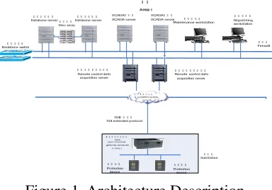
[image:2.612.209.401.453.587.2]There are two relay protection remote control modules, including application processing module and data acquisition module. The application processing module is deployed in work stations in Security Area I, while the data acquisition module is deployed in the front communication server of Security Area I. Fig. 1 shows the overall architecture:
Figure 1. Architecture Description.
As per the technical specifications for remote control, relay protection remote control is realized by means of three parts, namely, master dispatching and control station, substation and data transmission channel.
a) Relay protection remote control is implemented at the master station end relying on smart grid dispatching and control system, complying with the principle of integration, and making the best of and supported by modules provided by the basic platform of smart grid dispatching and control system such as database management, network communication, permission management and alarm service. Meanwhile, uniform HMI is used for monitoring and operation.
automatic safety device, and also status information and settings of relay protection and automatic safety device to the master dispatching and control station, and realizes conversion of network protocol between the substation layer and the dispatching data network.
c) For relay protection remote control, the dispatching data network serves as the data transmission channel between the master dispatching and control station and substation and does not affect secure data transmission of the existing dispatching system.
Software Module
Relay protection remote control module is composed of five sub modules, including communication module, HMI, permission management, alarm service and database management, detailed as follows:
Telecommunication module
This module is responsible for communication link management, parsing and encapsulation of Protocol 104+103 messages, message monitoring, saving, etc. After the operator sends a specific operating command via the HMI, this module performs data analysis, encapsulates this command into a 104+103 message, sends this message to the data communication gateway computer in Area I, monitors and parses the message returned from this gateway computer, and then sends the returned message back to the background program.
HMI
HMI is a medium of information transmission and exchange between the operator and the system. In additions to primitives shown in a conventional bay diagram, dynamic data primitives of protection soft plate, operating setting area number and protection device are added for the system for the operator to directly monitor and operate the system. Maintenance personnel can complete model and reference setting library maintenance via dedicated maintenance interfaces.
Permission Management
In the permission management module, different permissions are set for different users and operation items. O&M personnel have the permission to conduct model maintenance and reference setting library maintenance, and monitoring personnel have the permission to conduct remote control and monitoring. By this module, clear work division and cooperation can be realized in practical operation, and mal operation can be avoided technically. As a result, operation reliability and success rate can be improved.
Alarm Service
The alarm service module can send such system operation contents as operation item, implementation time, operator and operation node to the real-time alarm window, and save alarm information into the history alarm database for filing and future reference.
Database Management
Database management includes real-time database management and commercial database management. A real-time database, by providing high-speed local access interface and supporting data relation description and retrieval, can provide means for data sharing and fast interaction between sub modules. Commercial database management which covers model data and historical data features favorable structure, integrity and reliability, and is mainly for storage of protection device and its setting model, reference setting value, and alarm record.
Communication module
Database management
HMI Permission
management
Alarm service
Send command
Return the result
Judge permiss ion
Return the result Save model
[image:4.612.137.476.38.205.2]Send alarm Call data
Figure 2. Data stream inside module.
Model Maintenance
Soft plate switching of relay protection remote control module is realized via remote control based on Protocol 104, setting area switching is realized via remote dispatching based on Protocol 104, and protection device setting calling and modification are realized based on Protocol 104+103.
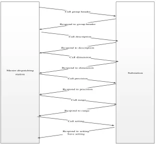
Remote signaling point number and remote control point number of protection soft plate, and remote metering point number and remote dispatching point number of setting area share the same data point table with four conventional remote points of SCADA system. Protection setting model covers such information as setting description, dimension, range and precision. Such information is returned based on Protocol 104+103 general service.
Ma ster dispatching
station Substation
Ca ll group heade r
Respond to group header
Call dimension Call desc ription
Re spond to description
Respond to dimension
Ca ll pre cision
Respond to precision
Ca ll ra nge
Respond to range
Ca ll setting
Re spond to se tting Save setting
[image:4.612.141.453.379.668.2]against the Actual Setting Sheet, and upon confirmation save these settings into the master station database as reference settings. In the event of modification of device setting in local mode, the master dispatching station shall be informed to maintain the reference library again.
The specific calling process is shown in Fig. 3:
Function Implementation
Remote Reclosing (Automatic Bus Transfer) Soft Plate Switching
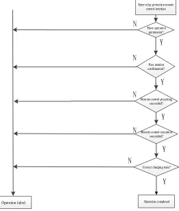
Soft plate switching for such functions of protection device as reclosing and automatic bus transfer is implemented via standard remote control function based on Protocol 104. The data communication gateway computer in Area I normally sends up, in a full remote signaling data manner, reclosing (automatic bus transfer) soft plate state and the corresponding reclosing (automatic bus transfer) soft plate charging state signals. After the remote control, this gateway computer, by changing the remote signaling mode, returns switching state of reclosing (automatic bus transfer) soft plate and also the corresponding charging state. Relay protection remote control module take these two kinds of signals as Double Confirmation signals of soft plate switching.
[image:5.612.126.387.367.675.2]After entering the remote control interface in the operation bay and checking substation name, device name, and plate name, the operator sends to designated monitoring computer monitoring request which may be accepted or refused by the monitor after a second confirmation of the information. The operator can perform remote control only after the confirmation. Remote control includes two steps, namely presetting and implementation. After implementation, plate state and charging state can be combined to judge whether the remote control is succeeded.
Fig. 4 shows the flow of soft plate switching:
Enter relay pr otection remote contr ol interface
Operation failed
Remote control pr esetting succeeded? Pass monitor confirmation? Have operation
per mission?
Remote control execution succeeded?
Operation completed Correct charging state?
N
N
N
N
Y
Y
Y
Y N
Y
Remote Operating Setting Area Switching
The current setting area of protection device is returned in a remote metering mode based on Protocol 104. In case of any change of the setting area number, it will be returned actively to ensure timeliness and meet monitoring requirement. After entering the setting area switching interface and selecting the target setting area, the operator will start the setting area switching process. The system will prompt to call the actual setting of the target setting area, compare it with the reference setting in the master station database, send monitoring command to the monitor after the comparison, send remote dispatching command of setting area switching after approval of the monitor, and receive feedback information about whether the remote dispatching is succeeded and also remote metering data of change of setting area number. It can be primarily determined that the operation is succeeded if such information is received. The system will subsequently call setting of the current setting area and compare it against the reference setting in the master station database. If the comparison indicates that the setting is consistent with the reference setting, i.e. Double Confirmation condition is met, it can be determined that setting area switching is succeeded. Fig. 5 shows the flow of protection setting area switching in a remote dispatching manner.
Enter relay pr otectio n remote con tr ol in terface
Pass data r atio nality judgment?
Settin g area switch ing failed
Call actual settin g of target setting ar ea
Actual setting of target setting ar ea is cor rect o r n ot th rou gh comp ariso n
with reference library
Send remo te d ispatchin g command of settin g area
switching
Call actual settin g of the curr ent setting ar ea
Co nsistent through settin g check?
Settin g area switch ing succeeded Rem ote meter in g data of
chan ge of setting area number is sent up?
Co nsistent check result of actual setting? Pass permission
authen tication?
Pass monitor monitoring?
N
Y N
Y
Y
Y
Y N
N
Y
N
Y N
N
Figure 5. Flow charts of setting area switching.
Remote Protection Setting Modification
“Write Confirmation” command will be sent down. If a “Write Confirmed” command returned from the substation end is received, a setting “Write Execution” command; otherwise, the operation will end. If a “Write Succeeded” command returned from the substation end is received, it indicates that the device has began set the setting. The master station will call again the target area setting for the operator to check whether the modification is succeeded and save it into the reference database.
Ente r re lay protection remote control interfa ce
Send called a ctual setting
Substation returns actual setting
Pass data rationality check?
Send Write Confirmation command
Sub-stati on ret urns r esponse c om mand
to Wr ite Confir mation? Operation e nded
Alarm
Send Write Execution command
Sub-station returns response command to Write Execution?
Send called a ctual setting
Re turn actual setting
Che ck modified setting N
Y
N
Y
N
Y
Figure 6. Flow charts of setting modification.
Error Prevention Mechanism and Data Check
Relay protection remote control application module must ensure safe and stable practical operation. As a result, this system must realize process control and automatic data check for all remote control steps to standardize the overall operation process and avoid serious consequences resulting from any negligence.
Data Model and Automatic Data Check
At the modeling stage, the system conducts automatic character check for setting description and dimension to identify invalid characters. For setting modification, the input setting and setting attributes (for example, data type, dimension, precision) will be checked automatically. In the event of any error found in the check, an alarm will be given.
For setting area switching and setting modification, setting comparison is required. The system will warn the operator by automatic comparison and highlighting inconsistent setting, to effectively avoid possible negligence or error in manual check.
Permission Control
The system strictly reviews model storage, view and modification permission of the reference database. Only designated maintenance personnel have the permission to modify the reference setting library and setting model. The reference library, once updated, is saved in the database with time stamp and user name indicated. For setting area switching, the system automatically chooses the latest reference setting for comparison.
setting modification. All of these operations can be implemented successfully only after approval of the operator and the monitor.
Process Control
Provided with strictly process control mechanism, the system can guide, via a Wizard HMI, the user to complete operations step by step following the established process. The user can proceed to the next step only when the advancing condition is met, otherwise, the operation will be ended and the user prompted, so as to effectively avoid maloperation.
Monitoring by Other Computer
Relay protection remote control shall be completed by operator and monitor. Different operation permissions shall be defined for remote control and monitoring to avoid single-person maloperation. Before sending of a remote operating command, the system sends operation details to the monitoring computer and the next step can be started only with monitor acknowledgment.
Alarm Log Management
The system records all operation steps and details, including operator, operation time, operation node, name of operation object, values before and after modification, operation result, etc., sends such information to the alarm window and saves the information into the historical database. The system also supports query based on such filter conditions as time, substation, device and operation, for the convenience of post tracking.
System Characteristics
This module is designed based on the new generation of smart grid dispatching and control system, complies with technical specifications of State Grid Corporation of China, realizes uniform format of communication protocol between master station and substation manufacturers, and has operation implementation modes standardized. For data modeling, auto modeling and manual maintenance are adopted. After pre-evaluation of data rationality and consistency by the program, alarms or error prompts are sent based on the severity level for subsequent handling by the maintenance personnel. By this way, workload of data maintenance is reduced, system maintenance become easier, and strong support is given to daily work of dispatching & control discipline.
Error prevention mechanism is the top priority of relay protection remote control and security and stability are the primary issues. This module has been provided with a rigorous handling mechanism for such major issues as security and stability. Standard operation procedures have been established, and rigorous control has been realized in data check, permission control, monitoring by other computer, log management, etc. To facilitate engineering commissioning, single commission mode can be used for substation connection to improve the efficiency, and monitoring by other computer can be adopted after official operation to ensure system security.
Conclusion
The relay protection remote control application module based on smart grid dispatching and control system described in this article has been established in the dispatching and control system of a province and has been put into service. According to the actual operation, in addition to ensure security and stability, this system can also realize rapid soft plate switching, setting area switching and setting modification, and thus significant improve work efficiency, management level of relay protection, and integration and coordination of monitoring, protection and automation.
Reference
[1] Rong, L. Wang Yonghong, W and Huixian, Z, Application of Integrated System of Intelligent Dispatch and Centralized Control in Hebei Southern Power Grid, Relay. China, vol. 40, pp. 151-155, (2012).
[2] Huimin, D. Feiyue, H. Zhihong, L. et al. Online Setting Management System Based on EMS and Fault Information System, Automation of Electric Power Systems. China, vol 30, pp. 97-99, (2006).
[3] Qing, L. Wenlong, W. Research on remote safety modification scheme of relay protection setting, Relay. China, vol. 42, pp. 139-143, (2014).
[4] Enyan, X. Yongwei, P. Mingyi, H. et al. Design and realization of protection communication and remote operation functions for centralized control systems of 500 kV unattended substations East China Electric Power. China, vol. 36, pp. 47-51, (2008).
[5] Dongfang. H, Yahui, S. Study and Realization for Measures of Mis-Operation-Prevention during the whole Course of Turn on and Draw off of Protection Pressure Plates, Fujian Power and Electrical Engineering. China, vol 28, pp. 54-56, (2008).
[6] Dongsheng, W. Dongxia, C. The Commissioning and Ceasing Principles for Protecting Plate in Substations, Northeast Electric Power Technology. China, vol. 28, pp. 41-43, (2007)