Achilleos, Paris
Design optimisation of a diffuser for a turbocharger compressor stage
Original Citation
Achilleos, Paris (2014) Design optimisation of a diffuser for a turbocharger compressor stage. Masters thesis, University of Huddersfield.
This version is available at http://eprints.hud.ac.uk/id/eprint/23751/
The University Repository is a digital collection of the research output of the University, available on Open Access. Copyright and Moral Rights for the items on this site are retained by the individual author and/or other copyright owners. Users may access full items free of charge; copies of full text items generally can be reproduced, displayed or performed and given to third parties in any format or medium for personal research or study, educational or notforprofit purposes without prior permission or charge, provided:
• The authors, title and full bibliographic details is credited in any copy; • A hyperlink and/or URL is included for the original metadata page; and
• The content is not changed in any way.
For more information, including our policy and submission procedure, please contact the Repository Team at: [email protected].
Design Optimisation of a Diffuser for a Turbocharger Compressor
By Paris Achilleos, School of Computing and Engineering, University of Huddersfield, UK (2014)
FOR A
T
URBOCHARGER
C
OMPRESSOR
S
TAGE
Paris Achilleos
M(Res)
2014
University of Huddersfield
Design Optimisation of a Diffuser for a Turbocharger Compressor
By Paris Achilleos, School of Computing and Engineering, University of Huddersfield, UK (2014)
ii The need for energy saving within the automotive industry becomes greater each year due to the continued pollution of the environment from the fossil fuels, and the amount of NOx emissions released in the environment from ground vehicles. Turbochargers are among those components that provide solutions to the energy saving for automotive vehicles, especially for the commercial division of ground vehicles. Significant developments in this field have been witnessed in the last decade using both the numerical and experimental investigations. However, the regulations of E.U regarding the energy saving has motivated the automotive industry to investigate new methods for improving the performance of turbochargers, decreasing the fuel consumption and lowering the emissions release in the environment from ground vehicles. Hence, this numerical investigation is primarily focused on the optimisation of the diffuser of a turbocharger compressor stage.
Design Optimisation of a Diffuser for a Turbocharger Compressor
By Paris Achilleos, School of Computing and Engineering, University of Huddersfield, UK (2014)
iii
The author of this thesis (including any appendices and/or schedules to this thesis) owns any copyright in it (the “Copyright”) and he has given The University of Huddersfield the right to use such Copyright for any administrative, promotional, educational and/or teaching purposes.
Copies of this thesis, either in full or in extracts, may be made only in accordance with the regulations of the University Library. Details of these regulations may be obtained from the Librarian. This page must form part of any such copies made.
Design Optimisation of a Diffuser for a Turbocharger Compressor
By Paris Achilleos, School of Computing and Engineering, University of Huddersfield, UK (2014)
iv First and most importantly, I would like to acknowledge my family and my supervisor Prof. Rakesh Mishra who provided support and encouragement throughout this study and made it possible. I would also like to acknowledge my friend Dr. Taimoor Asim who provided valuable help and support throughout this project. I cannot express my gratitude enough to Prof. Rakesh Mishra.
Design Optimisation of a Diffuser for a Turbocharger Compressor
By Paris Achilleos, School of Computing and Engineering, University of Huddersfield, UK (2014)
v Abstract ... II
Declaration ... III
Acknowledgements ... IV
Contents ... V
List of Figures ... IX
List of Tables ... XIII
Chapter 1 Introduction... 1
1.1 Introduction to Turbocharger ... 2
1.2 Background of Turbochargers ... 2
1.3 Working of a Turbocharger ... 3
1.4 Components of a Turbocharger Compressor Stage ... 4
1.4.1 Self-Recirculation Casing Treatment ... 4
1.4.2 The Impeller ... 5
1.4.3 Diffuser ... 5
1.4.4 Volute ... 6
1.5 Types and Applications of Turbochargers ... 7
1.6 Performance Characteristics of a Turbocharger Compressor Stage ... 8
1.6.1 Pressure Ratio ... 9
1.6.2 Isentropic Efficiency ... 9
1.7 Flow Characteristics in a Diffuser ... 11
1.7.1 Boundary Layer Separation ... 12
1.7.2 Increase in Length ... 13
1.7.3 Sudden Expansion ... 13
1.8 Diffusers Performance Optimisation ... 14
Design Optimisation of a Diffuser for a Turbocharger Compressor
By Paris Achilleos, School of Computing and Engineering, University of Huddersfield, UK (2014)
vi
Chapter 2 Literature Review ... 17
2.1 Introduction ... 18
2.2 Performance Characteristics of a Turbocharger Compressor Stage ... 18
2.3 Existing Designs and Design Considerations ... 20
2.4 Optimisation of a Turbocharger Compressor Diffuser ... 23
2.5 Scope of Research ... 29
2.6 Specific Research Objectives ... 30
Chapter 3 Numerical Modelling of a Centrifugal Compressor Stage ... 31
3.1 Introduction ... 32
3.2 Working of CFD Codes ... 32
3.3 Numerical Formulation of Fluid Flow ... 35
3.3.1 Conservation of Mass ... 35
3.3.2 Conservation of Momentum ... 36
3.3.3 Conservation of Energy ... 36
3.3.4 Equations of State ... 37
3.3.5 Navier – Stokes equations ... 38
3.4 Pre–Processing ... 38
3.4.1 Geometry of the Compressor Stage ... 38
3.4.2 Meshing of the Flow Domain ... 39
3.5 Turbulence Modelling ... 41
3.6 Boundary Conditions ... 42
3.7 Multiple Reference Frame ... 43
3.8 Solver Settings ... 44
Design Optimisation of a Diffuser for a Turbocharger Compressor
By Paris Achilleos, School of Computing and Engineering, University of Huddersfield, UK (2014)
vii
4.2 Benchmark Tests ... 47
4.2.1 Static Pressure ... 49
4.2.2 Mach Number ... 50
4.2.3 Axial Velocity ... 50
4.2.4 Radial Velocity ... 51
4.2.5 Azimuthal Velocity ... 52
4.2.6 Static Pressure ... 54
4.3 Baseline Diffuser Performance Characteristics ... 54
4.3.1 Static Pressure ... 57
4.3.2 Mach Number ... 60
4.3.3 Axial Velocity ... 64
4.3.4 Radial Velocity ... 67
4.3.5 Azimuthal Velocity ... 70
4.3.6 Static Temperature ... 73
4.4 Static Pressure Recovery... 76
Chapter 5 Optimisation of Diffuser Geometry ... 78
5.1 Geometrical Configurations of the Diffuser ... 79
5.2 Performance Evaluation of the Modified Diffuser Geometries ... 83
5.3 Optimised Diffuser Analysis... 95
5.3.1 Static Pressure ... 96
5.3.2 Mach Number ... 99
5.3.3 Axial Velocity ... 102
5.3.4 Radial Velocity ... 105
5.3.5 Azimuthal Velocity ... 108
Design Optimisation of a Diffuser for a Turbocharger Compressor
By Paris Achilleos, School of Computing and Engineering, University of Huddersfield, UK (2014)
viii
Chapter 6 Conclusions ... 115
6.1 Research Problem Synopsis ... 116
6.2 Research Aim and Major Achievements ... 116
6.3 Thesis Conclusions ... 117
6.4 Thesis Contribution ... 118
6.4 Recommendations for Future Work... 119
Design Optimisation of a Diffuser for a Turbocharger Compressor
By Paris Achilleos, School of Computing and Engineering, University of Huddersfield, UK (2014)
ix
Figure 1.1 Turbocharger ... 2
Figure 1.2 Working of a Turbocharger ... 3
Figure 1.3 Self-Recirculating Casing Treatment ... 4
Figure 1.4 Impeller of a Turbocharger Compressor Stage ... 5
Figure 1.5 A Vaneless Diffuser ... 6
Figure 1.6 Volute ... 6
Figure 1.7 Axial Compressor ... 7
Figure 1.8 Radial Compressor ... 8
Figure 1.9 Total-to-Total Pressure Ratio variations in the Compressor Stage of a Turbocharger ... 9
Figure 1.10 Efficiency variations in the Compressor Stage of a Turbocharger... 10
Figure 1.11 Cut Section of a Turbocharger Compressor Stage ... 11
Figure 1.12 Diffuser Geometry ... 12
Figure 1.13 Boundary Layer separation within a Conical Diffuser ... 13
Figure 1.14 Flow phenomenon when A3=A2 ... 13
Figure 1.15 Flow phenomenon when A3>A2 ... 14
Figure 2.1 Pinched Diffuser ... 22
Figure 2.2 Vaneless diffuser entry configurations: a) Unpinched, b) Front Pinched, c) Rear Pinched, d) Double Pinched and e) Constant Area (b 1/r) ... 24
Figure 2.3 Vaneless Diffuser Design having b2/b1=1.07 ... 26
Figure 2.4 Converging Diverging diffusers ... 28
Figure 2.5 Conical Diffuser’s Geometrical Features ... 29
Figure 3.1 CFD Solver ... 34
Figure 3.2 Overview of CFD Modelling... 34
Figure 3.3 Baseline Geometry ... 39
Figure 3.4 Flow Domain Mesh (Cut-Section) ... 40
Figure 3.5 Diffuser Mesh ... 40
Figure 3.6 Multiple Reference Frame modeling ... 44
Design Optimisation of a Diffuser for a Turbocharger Compressor
By Paris Achilleos, School of Computing and Engineering, University of Huddersfield, UK (2014)
x
Figure 4.3 Variations in absolute static pressure (in atm) at 4th design point and 60,000rpm ... 49
Figure 4.4 Variations in Mach number at 4th design point and 60,000rpm ... 50
Figure 4.5 Variations in axial velocity (in m/s) at 4th design point and 60,000rpm ... 51
Figure 4.6 Variations in radial velocity (in m/s) at 4th design point and 60,000rpm ... 52
Figure 4.7 Variations in azimuthal velocity (in m/s) at 4th design point and 60,000rpm ... 53
Figure 4.8 Flow of air within the diffuser ... 53
Figure 4.9 Variations in static temperature (in K) at 4th design point and 60,000rpm ... 54
Figure 4.10 Flow parameters measuring stations (a) Orientation of diffuser (b) measuring stations front view (c) measuring stations side view ... 56
Figure 4.11 Variations in absolute static pressure (in atm) within the diffuser at 4th design point and 60,000rpm ... 57
Figure 4.12 Absolute static pressure variations within the diffuser at 4th design point and 60,000rpm corresponding to (a) 0° (b) 90° (c) 180° (d) 270° ... 58
Figure 4.13 Variations in Mach number within the diffuser at 4th design point and 60,000rpm ... 61
Figure 4.14 Mach number variations within the diffuser at 4th design point and 60,000rpm corresponding to (a) 0° (b) 90° (c) 180° (d) 270° ... 61
Figure 4.15 Variations in axial velocity (in m/s) within the diffuser at 4th design point and 60,000rpm ... 64
Figure 4.16 Axial velocity variations within the diffuser at 4th design point and 60,000rpm corresponding to (a) 0° (b) 90° (c) 180° (d) 270° ... 65
Figure 4.17 Variations in radial velocity (in m/s) within the diffuser at 4th design point and 60,000rpm ... 67
Figure 4.18 Radial velocity variations within the diffuser at 4th design point and 60,000rpm corresponding to (a) 0° (b) 90° (c) 180° (d) 270° ... 68
Figure 4.19 Variations in azimuthal velocity (in m/s) within the diffuser at 4th design point and 60,000rpm ... 70
Design Optimisation of a Diffuser for a Turbocharger Compressor
By Paris Achilleos, School of Computing and Engineering, University of Huddersfield, UK (2014)
xi Figure 4.22 Static temperature variations within the diffuser at 4th design point and 60,000rpm corresponding to (a) 0° (b) 90° (c) 180° (d) 270° ... 74
Figure 4.23 Static Pressure Recovery within the Baseline Diffuser ... 77
Figure 5.1 Pinch locations on the diffuser (a) At diffuser inlet (b) 10% from diffuser inlet (c) 20%
from diffuser inlet (d) 30% from diffuser inlet (e) 40% from diffuser inlet (f) 50% from diffuser
inlet ... 79
Figure 5.2 Sudden expansion of the diffuser ... 82
Figure 5.3 Variations in Pressure Ratio for various diffuser configurations for b2/b1 = 1.05 at
60,000rpm ... 83
Figure 5.4 Variations in Efficiency for various diffuser configurations for b2/b1 = 1.05 at 60,000rpm
... 84
Figure 5.5 Variations in Pressure Ratio for various diffuser configurations for b2/b1 = 1.07 at
60,000rpm ... 85
Figure 5.6 Variations in Efficiency for various diffuser configurations for b2/b1 = 1.05 at 60,000rpm
... 86
Figure 5.7 Variations in Pressure Ratio for various diffuser configurations for b2/b1 = 1.13 at
60,000rpm ... 87
Figure 5.8 Variations in Efficiency for various diffuser configurations for b2/b1 = 1.13 at 60,000rpm
... 88
Figure 5.9 Variations in Pressure Ratio for various diffuser configurations for b2/b1 = 1.18 at
60,000rpm ... 89
Figure 5.10 Variations in Pressure Ratio for various diffuser configurations for b2/b1 = 1.18 at
60,000rpm ... 90
Figure 5.11 Variations in Pressure Ratio for various diffuser configurations for b2/b1 = 1.33 at
60,000rpm...91
Figure 5.12 Variations in Efficiency for various diffuser configurations for b2/b1 = 1.33 at
60,000rpm ... 92
Figure 5.13 Variations in Pressure Ratio for various suddenly expanding diffuser configurations at
Design Optimisation of a Diffuser for a Turbocharger Compressor
By Paris Achilleos, School of Computing and Engineering, University of Huddersfield, UK (2014)
xii Figure 5.15 Flow parameters measuring stations for the optimised diffuser ... 95
Figure 5.16 Variations in absolute static pressure (in atm) within the optimised diffuser at 4th design point and 60,000rpm ... 96
Figure 5.17 Absolute static pressure variations within the optimised diffuser at 4th design point and 60,000rpm corresponding to (a) 0° (b) 90° (c) 180° (d) 270° ... 97
Figure 5.18 Variations in Mach number within the optimised diffuser at 4th design point and 60,000rpm ... 99
Figure 5.19 Absolute Mach number variations within the optimised diffuser at 4th design point and 60,000rpm corresponding to (a) 0° (b) 90° (c) 180° (d) 270° ... 100
Figure 5.20 Variations in axial velocity (in m/s) within the optimised diffuser at 4th design point and 60,000rpm ... 102
Figure 5.21 Absolute axial velocity variations within the optimised diffuser at 4th design point and 60,000rpm corresponding to (a) 0° (b) 90° (c) 180° (d) 270° ... 103
Figure 5.22 Variations in radial velocity (in m/s) within the optimised diffuser at 4th design point and 60,000rpm ... 105
Figure 5.23 Absolute radial velocity variations within the optimised diffuser at 4th design point and 60,000rpm corresponding to (a) 0° (b) 90° (c) 180° (d) 270° ... 106
Figure 5.24 Variations in azimuthal velocity (in m/s) within the optimised diffuser at 4th design point and 60,000rpm ... 108
Figure 5.25 Absolute azimuthal velocity variations within the optimised diffuser at 4th design point and 60,000rpm corresponding to (a) 0° (b) 90° (c) 180° (d) 270° ... 109
Figure 5.26 Variations in static temperature (in K) within the optimised diffuser at 4th design point and 60,000rpm ... 111
Figure 5.27 Absolute static temperature variations within the optimised diffuser at 4th design point and 60,000rpm corresponding to (a) 0° (b) 90° (c) 180° (d) 270° ... 112
Design Optimisation of a Diffuser for a Turbocharger Compressor
By Paris Achilleos, School of Computing and Engineering, University of Huddersfield, UK (2014)
xiii
Table 3.1 Mesh Quality... 41
Table 3.2 Boundary Conditions ... 43
Table 4.1 Percentage differences in absolute static pressure at various measuring locations ... 60
Table 4.2 Percentage differences in Mach number at various measuring locations ... 63
Table 4.3 Percentage differences in axial velocity at various measuring locations ... 67
Table 4.4 Percentage differences in radial velocity at various measuring locations ... 70
Table 4.5 Percentage differences in azimuthal velocity at various measuring locations ... 73
Table 4.6 Percentage differences in static temperature at various measuring locations ... 76
Table 5.1 Diffuser design configurations for various pinch locations ... 81
Table 5.2 Diffuser design configurations for various divergent angles ... 82
Table 5.3 Percentage increase in pressure ratio between baseline and N/Nmax=0.5 diffuser geometries for b2/b1=1.05 at 60,000rpm ... 83
Table 5.4 Percentage increase in efficiency between baseline and N/Nmax=0.5 diffuser geometries for b2/b1=1.05 at 60,000rpm ... 84
Table 5.5 Percentage increase in pressure ratio between baseline and N/Nmax=0.5 diffuser geometries for b2/b1=1.07 at 60,000rpm ... 85
Table 5.6 Percentage increase in efficiency between baseline and N/Nmax=0.5 diffuser geometries for b2/b1=1.07 at 60,000rpm ... 86
Table 5.7 Percentage increase in pressure ratio between baseline and N/Nmax=0.5 diffuser geometries for b2/b1=1.13 at 60,000rpm ... 87
Table 5.8 Percentage increase in efficiency between baseline and N/Nmax=0.5 diffuser geometries for b2/b1=1.13 at 60,000rpm ... 88
Table 5.9 Percentage increase in pressure ratio between baseline and N/Nmax=0.5 diffuser geometries for b2/b1=1.18 at 60,000rpm ... 89
Table 5.10 Percentage increase in efficiency between baseline and N/Nmax=0.5 diffuser geometries for b2/b1=1.18 at 60,000rpm ... 90
Design Optimisation of a Diffuser for a Turbocharger Compressor
By Paris Achilleos, School of Computing and Engineering, University of Huddersfield, UK (2014)
xiv Table 5.13 Percentage increase in pressure ratio between baseline and suddenly expanding diffuser
geometries at 60,000rpm ... 93
Table 5.14 Percentage increase in efficiency between baseline and suddenly expanding diffuser geometries at 60,000rpm ... 94
Table 5.15 Percentage differences in absolute static pressure at various measuring locations ... 99
Table 5.16 Percentage differences in Mach number at various measuring locations ... 102
Table 5.17 Percentage differences in axial velocity at various measuring locations ... 105
Table 5.18 Percentage differences in radial velocity at various measuring locations ... 108
Table 5.19 Percentage differences in azimuthal velocity at various measuring locations ... 111
Design Optimisation of a Diffuser for a Turbocharger Compressor
By Paris Achilleos, School of Computing and Engineering, University of Huddersfield, UK (2014)
1
C
HAPTER
1
I
NTRODUCTION
his chapter provides an overview of current automotive vaneless diffusers and their associated components. In this review, the basic performance parameters of an automotive turbocharger are discussed, focusing on the centrifugal compressor stage and exploring the mechanisms that affect the performance output of a turbocharger. Additionally, the importance of vaneless diffusers for the design and development of radial turbo-machines are discussed. Existing design configurations and optimisation procedures were also examined, in order to explore some of the key geometric characteristics that are related to the vaneless diffuser’s performance output. This chapter also highlights the importance of the interaction of diffuser-volute, where a number of key questions are raised that correspond to the recent needs of turbochargers for higher efficiencies and reduction of package sizing. The reasons and purpose for carrying out this research, and the main aims of this study are emphasised in this chapter.
Design Optimisation of a Diffuser for a Turbocharger Compressor
By Paris Achilleos, School of Computing and Engineering, University of Huddersfield, UK (2014)
2
1.1
Introduction to Turbochargers
[image:17.612.182.428.176.415.2]Turbochargers are amongst the most complicated and sophisticated pieces of engineering that require high precision and are commonly used to a great extent for a variety of internal combustion engines. For the automotive applications, the turbocharger utilizes the waste energy from the exhaust gas, which is driven into the turbine housing. A typical turbocharger is shown in figure 1.1.
Figure 1.1 Turbocharger [1]
1.2
Background of Turbochargers
Design Optimisation of a Diffuser for a Turbocharger Compressor
By Paris Achilleos, School of Computing and Engineering, University of Huddersfield, UK (2014)
3
1.3
Working of a Turbocharger
[image:18.612.122.499.174.437.2]When the combustion process takes place in the engine, the waste energy exits in a form of exhaust gas. The flow enters the turbine housing from the turbine volute (as shown in figure 1.2). The flow enters the wheel in a radial direction, which forces the turbine to rotate at high speeds. This process produces torque that is delivered from the shaft to the compressor’s impeller.
Figure 1.2 Working of a Turbocharger [2]
Design Optimisation of a Diffuser for a Turbocharger Compressor
By Paris Achilleos, School of Computing and Engineering, University of Huddersfield, UK (2014)
4
1.4
Components of a Turbocharger Compressor Stage
The main components of a typical turbocharger’s compressor stage are discussed below.
Self-Recirculation Casing Treatment 1.4.1
Self-Recirculation Casing Treatment (SRCT) is the most modern method that increases a turbocharger’s operational range by interfering with the boundary layers at the entry of the diffuser. This is possible due to the static pressure field variations under specific operating conditions as suggested by Hathaway et al [3] and Sivagnanasudaram et al [4]. For a typical design in automotive turbochargers, the SRCT usually consists of grooves, circumferential into the inlet duct, with two bleeds (as shown in figure 1.3). The first bleed is before the inducer and the second one is after the inducer. Close to surge operating condition (which is one of the extremities of a turbocharger’s operation), the system recycles the low energy fluid from the bleed close to the impeller, and sends it back to the inducer through the first bleed. On the other hand, close to choke operating condition (which is the other extremity of a turbocharger’s operation), more flow is injected to the impeller through the bleed that is located close to the inducer. These two procedures can remove any kind of unsteadiness that can develop at the upstream of the diffuser.
Design Optimisation of a Diffuser for a Turbocharger Compressor
By Paris Achilleos, School of Computing and Engineering, University of Huddersfield, UK (2014)
5 The Impeller
1.4.2
The impeller is one of the most important components of a turbocharger’s compressor stage. The impeller is rotated by a shaft, connected to the wheel of the turbine stage of the turbocharger. The impeller transfers its energy to the incoming fluid, hence increasing fluid’s energy. This is achieved by momentum transfer mechanism. A typical impeller of a compressor is shown in figure 1.4.
Figure 1.4 Impeller of a Turbocharger Compressor Stage [2]
The fluid flow through the impeller is three-dimensional, the s three main velocity components being in axial direction (Cx), in radial direction (Cr), and in azimuthal or tangential direction (Cθ).
The incidents angle of the flow with the impeller is critical, affecting the performance of the compressor stage, and can generate series of instabilities, as discussed by Pinarbasi [5] and Japikse [6]. The shape of the blades drives the flow into a radial direction in order to discharge the fluid from the edge of the impeller blades.
Diffuser 1.4.3
Design Optimisation of a Diffuser for a Turbocharger Compressor
By Paris Achilleos, School of Computing and Engineering, University of Huddersfield, UK (2014)
6 Figure 1.5 A Vaneless Diffuser
The primary aim of a diffuser is to diffuse the air flow. Diffusion converts the kinetic energy of the fluid into its pressure. Hence, at the outlet of the diffuser, the flow velocity is lower and the fluid’s pressure is higher, as compared to diffuser’s inlet. Further discussion on diffusers flow characteristics is presented in section 1.7.
Volute 1.4.4
The volute collects and guides the flow from the diffuser. The flow is finally discharged from the volute through the delivery pipe. The volute decreases the non-uniformities and turbulence of flow entering the delivery pipe (Aungier [7]). Typical volute geometry is shown in figure 1.6.
Design Optimisation of a Diffuser for a Turbocharger Compressor
By Paris Achilleos, School of Computing and Engineering, University of Huddersfield, UK (2014)
7 The volute has a critical area on which the overall stage performance depends on. This is known as tongue. Its size and geometry has a significant effect on the performance of the centrifugal compressors. If the inclination of the tongue does not conform to the flow direction, shock losses and distributed flow conditions in this area will arise.
1.5
Types and Applications of Turbochargers
Turbochargers are being used in a variety of industrial applications like aerospace, marine, hydro-turbines, larger centrifugal chillers for commercial and industrial applications etc. Considering the challenges for each individual application, the turbochargers were modified accordingly. Different applications allow the engineers to explore in detail the geometric characteristics of turbochargers, and to modify each component accordingly. The main configuration that distinguishes the turbomachines into two divisions is the impeller design. The impeller can have axial or radial configurations for the turbine choice, but the compressor stage consists mostly of centrifugal configuration, although depending on the application, axial-radial combinations can be employed. For example, axial compressors are mostly employed in the aerospace industry for the flight and stability purposes (figure 1.7). The use of centrifugal compressors is common in small airplanes and automotive vehicles (figure 1.8).
Design Optimisation of a Diffuser for a Turbocharger Compressor
By Paris Achilleos, School of Computing and Engineering, University of Huddersfield, UK (2014)
8 Figure 1.8 Radial Compressor [9]
Automotive turbocharging requirements are different from those of gas turbines. The stability and flow range are the essential parameters for automotive engines. More specifically, the automotive engines operate from idle to full power. Automotive turbochargers are used in all the categories of ground vehicles i.e. commercial, private (passenger cars) and racing applications. Each category has its own specific needs and the turbocharger performance is adjusted accordingly. For example, sports cars need to achieve higher pressure ratios and efficiencies, with operating range being of secondary importance. On the other hand, commercial vehicle turbochargers (heavy-duty engines) give more priority to wider operating range, and in some cases sacrifice efficiency, which is the main reason why vaneless diffusers are employed instead of vaned diffusers. However, some subcategories of commercial vehicles require higher efficiencies rather than wider operating range. These kinds of modifications can be made by modifying the geometry of the inlet section or by employing a vaneless diffuser, depending on the specific needs of each application.
1.6
Performance Characteristics of a Turbocharger Compressor Stage
Design Optimisation of a Diffuser for a Turbocharger Compressor
By Paris Achilleos, School of Computing and Engineering, University of Huddersfield, UK (2014)
9 Pressure Ratio
1.6.1
The compressor pressure ratio is defined as the ratio of pressure at the outlet to the pressure at the inlet of the compressor stage, which is represented mathematically as follows:
[
]
(1.1)Figure 1.9 depicts the variations in total-to-total pressure ratio with respect to mass flow rate passing through the compressor stage of a turbocharger at various operating speeds. This graph is commonly known as a Compressor Map. The left and right extremities of pressure ratio curves are dictated by the surge and choke conditions respectively.
Figure 1.9 Total-to-Total Pressure Ratio variations in the Compressor Stage of a Turbocharger
Isentropic Efficiency 1.6.2
The isentropic efficiency of a compressor is defined as the ratio of the isentropic work required to raise the pressure of a gas, to the actual work input.
(1.2)
Design Optimisation of a Diffuser for a Turbocharger Compressor
By Paris Achilleos, School of Computing and Engineering, University of Huddersfield, UK (2014)
10
(1.3)
Using the compressible flow relationship between temperature and pressure (by substituting Tout,isentropic in equation (1.3)), the isentropic efficiency of the compressor can be expressed as:
[
]
(1.4)
Figure 1.10 depicts the variations in total-to-total efficiency with respect to mass flow rate passing through the compressor stage of a turbocharger at various operating speeds. The left and right extremities of efficiency curves are dictated by the surge and choke conditions respectively.
Figure 1.10 Efficiency variations in the Compressor Stage of a Turbocharger
Design Optimisation of a Diffuser for a Turbocharger Compressor
By Paris Achilleos, School of Computing and Engineering, University of Huddersfield, UK (2014)
11 Surge is the other extreme flow phenomenon represented by the left most operating points on a turbocharger compressor map. Under surge condition, the working fluid does not possess enough energy to support air flow through the compressor stage. It occurs when the pressure of the airflow in the compressor is actually higher than what it can physically maintain.
1.7
Flow Characteristics in a Diffuser
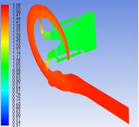
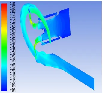
In order to understand the flow behaviour within the diffuser of a turbocharger compressor stage, it is important to first visualise the geometrical configuration of a typical turbocharger compressor diffuser. Figure 1.11 shows a cut section of a turbocharger compressor stage. It can be clearly seen that a diffuser basically consistes of two parallel walls, where the flow diffuses in order to increase the fluid’s pressure at the outlet of the diffuser. Diffusion occurs because the diffuser’s outlet radius is more than a diffuser’s inlet radius, increasing the effective area for the flow to take place, and hence diffusing the flow. Furthermore, the two walls of the diffuser are known as shroud wall and the hub wall. Shroud wall is the one which is closer to the inlet of the compressor stage. The inlet section of the shroud wall is curved, while the outlet section is bulged, forming the tongue of the compressor. The hub wall is a straight wall.
Figure 1.11 Cut Section of a Turbocharger Compressor Stage [9]
Design Optimisation of a Diffuser for a Turbocharger Compressor
By Paris Achilleos, School of Computing and Engineering, University of Huddersfield, UK (2014)
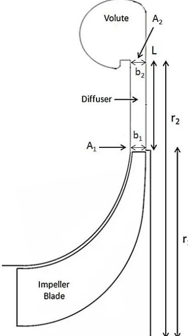
12 cross-sectional areas at the inlet (A1) and outlet (A2) of a diffuser. Furthermore, larger the length
of a diffuser, the less abrupt the area change would be. In automotive diffusers, it was shown that r2/r1 ratios higher than 1.8 results in flow losses for the system (Brown [10]), where r1 and r2
[image:27.612.209.395.160.492.2]represent the radius, from the axis of rotation, to the diffuser inlet and diffuser outlet sections respectively (see figure 1.12).
Figure 1.12 Diffuser Geometry
Boundary Layer Separation 1.7.1
The main flow characteristic in a diffuser is the positive pressure gradient that favours the development of boundary layers and sometimes flow separation. Sovan [11] states that the positive pressure gradient depends mostly on the ratio of A2/A1 and the length of the diffuser (L).
Increase in area ratio A2/A1 increases the positive pressure gradient. Thus, there is a higher
Design Optimisation of a Diffuser for a Turbocharger Compressor
By Paris Achilleos, School of Computing and Engineering, University of Huddersfield, UK (2014)
13 Figure 1.13 Boundary Layer separation within a Conical Diffuser [12]
Increase in Length 1.7.2
The increase in the length of a diffuser, for a constant A2/A1 ratio, reduces the positive pressure
gradient as well as the possibility of flow separation, and hence results in higher pressure recovery. If A2/A1 ratio is constant, and connected with a straight section (A2=A3), then the
[image:28.612.213.404.78.211.2]reattached point of the boundary layer will be in the section (duct) that follows (Goulas [12]). This can be seen in figure 1.14.
Figure 1.14 Flow phenomenon when A3=A2 [12]
Sudden Expansion 1.7.3
Another example is that A2/A1 ratio remains constant, but the duct that follows the diffuser exit
section has a bigger area i.e. A3>A2. This consideration results in a higher-pressure rise within
the diffuser (Goulas [12]). Therefore, the sudden increase of area A3 provides a pressure rise
Design Optimisation of a Diffuser for a Turbocharger Compressor
By Paris Achilleos, School of Computing and Engineering, University of Huddersfield, UK (2014)
14 Figure 1.15 Flow phenomenon when A3>A2 [12]
1.8
Diffusers Performance Optimisation
The main consideration for optimal performance of a diffuser is the boundary layer separation that is close to the diffuser walls, and causes pressure drop within the diffuser. As the primary purpose of a diffuser is to increase the pressure, the pressure drop must be minimised. For a given A2/A1, the designer needs to investigate the formation of the boundary layer and its
consequent separation. This can be achieved with the following recommendations by Goulas [12]:
1. Modify/optimise the velocity distribution if it is not symmetric at the inlet of the diffuser. In order to achieve a symmetric velocity distribution, increase the length of the inlet section of the diffuser. This provides adequate time for the flow to fully develop and become symmetric
2. Optimise the area ratio (A2/A1) and the length of the diffuser. This can be achieved by
tuning the diffuser geometry and shape, for example to a planar shape. The boundary separation is thus limited in the region of high speed, and hence reduces the mixing effects and losses
3. Intercept the boundary layer, or even use combination of the previous methods. The SRCT is the most modern method that is employed for interception of boundary layers
1.9
Motivation
Design Optimisation of a Diffuser for a Turbocharger Compressor
By Paris Achilleos, School of Computing and Engineering, University of Huddersfield, UK (2014)
15 engine systems. This study focuses on the heavy-duty engine systems, and concentrates on improving the turbocharger performance, resulting in overall performance improvement of the engine system. Turbochargers can improve the engine performance with a significant reduction in fuel consumption, hence reducing engine emissions. Another challenging element for the turbocharger optimisation is the housing size, which needs to be made more compact for better integrity with the automotive engine.
From the general review carried out in this chapter regarding diffusers of a turbocharger compressor stage, key areas were identified for further investigations. These key areas focus on the design characteristics of the diffuser channel, and their effect on the flow structure. Furthermore, more in-depth research is required on the exit section of the diffuser in order to explore the mechanisms that affect the diffuser performance. Hence, detailed numerical investigations were carried out to analyse the performance of the diffuser for stable operating conditions, which corresponds to lower operating speeds of the turbocharger.
1.10
Research Aims
The specific research aims formulated for this research study are described in this section, whereas the detailed objectives are discussed after carrying out the literature review in the next chapter. The research aims of the current study are to:
1. Analyse the flow characteristics of the baseline diffuser of a turbocharger compressor stage at lower operating speeds
2. Develop an optimal design of the diffuser channel for turbocharger compressor stage
The aforementioned aims cover a wide range of operation of the turbocharger compressor stage, and hence are considered satisfactory for this study. Detailed literature review is presented in the next chapter, focusing on the aforementioned research aims, in order to fill any gaps in the existing literature.
1.11
Organisation of Thesis
Based on the discussion presented in the previous sections, the current thesis is structured as follows:
Chapter 1 provides an overview of turbocharger including diffuser related effects.. From this overview, the purpose for carrying out this research is described, which identifies key areas to be reviewed in Chapter 2.
Design Optimisation of a Diffuser for a Turbocharger Compressor
By Paris Achilleos, School of Computing and Engineering, University of Huddersfield, UK (2014)
16 for automatic optimisation techniques, available from commercial software packages, was also presented.
Chapter 3 documents the fundamental principles of Computational Fluid Dynamics (CFD). It includes the CFD modelling of the centrifugal compressor, including the solver settings and the appropriate boundary conditions that were specified. Furthermore, a detailed discussion on the Multiple Reference Frame (MRF) technique for rotating the impeller is discussed.
Chapter 4 demonstrates the capabilities of CFD solvers in predicting the performance of a turbocharger compressor stage. This also includes validation of the numerical results with the experimental data. Furthermore, it highlights the importance of CFD as a research and development tool for predicting the component performance at an early stage for industrial and non-industrial applications.
Chapter 5 consists of detailed studies on the effect of the geometrical parameters of the diffuser on the performance characteristics of the turbocharger compressor stage. The optimisation methodology was described, and different diffuser models were numerically evaluated. Based on the selection criteria, the optimum diffuser geometry was picked out and its complete flow analysis was included. The comparison of improved local and global flow characteristics against baseline model was highlighted in this chapter.
Chapter 6 concludes the findings of this study, clearly mentioning the goals achieved and contributions to existing knowledge. Recommendations for future work have also been included.
Design Optimisation of a Diffuser for a Turbocharger Compressor
By Paris Achilleos, School of Computing and Engineering, University of Huddersfield, UK (2014)
17
2
C
HAPTER
2
L
ITERATURE
R
EVIEW
he following chapter provides a detailed review of the available literature in the field of turbochargers, with emphasis on the compressor stage. The main areas addressed in this chapter are associated with diffuser optimisation techniques for improving compressor performance. Several geometric characteristics that affect the performance output of a vaneless diffuser were also examined. Amongst the geometric variables, the focus is primarily on the diffuser width, its effects on the overall efficiency, and the stability of the stage. Within these areas, specific limitations were identified, and used to define the scope of this study. The specific research objectives of this thesis were outlined in an effort to improve the efficiency of the turbocharger compressor stage from Cummins Turbo Technologies (CTT).
Design Optimisation of a Diffuser for a Turbocharger Compressor
By Paris Achilleos, School of Computing and Engineering, University of Huddersfield, UK (2014)
18
2.1
Introduction
In recent years, turbocharger optimisation was focused on the development of existing and new technologies, using both experimental and numerical techniques, concentrating on specific components that affect stage performance and increase the efficiency through traditional and modern optimisation methods. The most common components that are being improved are the impeller blades and the diffuser passage. The diffuser’s annular passage within the compressor section is a major research area for optimising the overall performance of the stage, and literature review of this aspect is the major focus of this chapter. This is mostly due to the low design and manufacturing costs associated with diffusers as compared to other components. Moreover, effective diffuser design can contribute to the improvement in the performance output of the turbocharger by increasing the efficiencies and reducing the fuel consumption. This chapter discusses the existing design configurations and technologies, concentrating on automotive applications, providing a clear and concise review of the major works conducted in this area, with special references of Senoon and Kinoshita [13], Jansen [14] and Japikse [15]. Additionally, the need for better understanding regarding the geometric construction of automotive diffusers was discussed. This chapter, emphasizes the effects of the specific geometric parameters on the compressor performance.
2.2
Performance Characteristics
of
a Turbocharger Compressor Stage
The previous chapter discussed the importance of a proficient design for both the impeller and diffuser in order to optimise the performance output of turbocharger compressors. The initial work in the area of divergent sidewall diffusers was carried out by Japikse [15], who optimised the performance of a turbocharger compressor stage. The performance output of the divergent diffuser channel was reported by the author as excellent, indicating that diffusers with more axial length can increase the overall performance output of a turbocharger compressor stage. During the investigation, a diffusion process at the inlet section of the diffuser passage was noticed that caused pressure drop upstream of the diffuser channel. The diffusion process mentioned can be explained from the variation of critical flow angle φ due to the increase of A2 (b2>b1) that causes
higher flow losses upstream of the impeller. The critical flow angle is the largest tangential angle with which the diffuser does not stall. As a result, the blades of the impeller had to be modified accordingly in order to match the requirements of the diffuser. This demonstrated the importance of a proficient match between impeller and diffuser for better performance output for turbocharger compressor stage. The published results from Japikse provided the turbocharger designers with an extra degree of freedom for diffuser design by diverging one wall of the diffuser.
Design Optimisation of a Diffuser for a Turbocharger Compressor
By Paris Achilleos, School of Computing and Engineering, University of Huddersfield, UK (2014)
19 three-dimensional flow. Optimisation of this specific section can reduce flow losses and provide higher static pressure rise. Literature suggests that a divergent wall diffuser has higher chances of flow losses resulting in the design process of non-parallel wall even more challenging (Goulas [12]). Still the most challenging task is to achieve an optimal match of all the three components for a variety of operating conditions, namely surge, choke and for several operating speeds, since it is known that the performance output of a turbocharger compressor stage varies with operating speeds.. This indicates that the flow regimes develop at each design point when the stage shifts from idle to full power. These variations of flow regimes need to be taken into account by the designer in the early stages of the design process.
As discussed earlier, the performance output of turbochargers was investigated by several researchers, prominent among them are Senoon and Kinoshita [13], Abdelhamid [16], Dickmann [17], Khalifallah [18] etc. They added a wide range of information in the field of turbocharger compressor stage operations. Furthermore, literature indicates that full stage models, or isolated components models, were used in order to study the performance of a turbocharger compressor for optimisation purposes. These methods have advantages and disadvantages in terms of computational time, prototype manufacturing, accuracy etc. More specifically, for numerical investigations, researchers prefer to model either only the impeller or a single blade passage, with or without the diffuser, in order to reduce computational time. Another common technique is the modelling of single diffuser passages, with or without volute configuration. Similar approaches were also observed in experimental investigations. This variety of techniques raise a series of questions regarding the accuracy and correlation of the results obtained from each individual investigation. The variety of the techniques mentioned above can provide reasonably accurate results regarding the overall performance output of a turbocharger compressor stage i.e. pressure ratio and efficiency. However, it might provide miss-leading information because of the absence of coupled effects. For example, in the case of an isolated diffuser test, if the turbulence levels downstream of the diffuser are not modelled accurately, it might lead to errors in computations. In another situation, if the length or the width of the diffuser modifies during the optimisation process, the critical flow angle will vary as well. As a result, the turbulence levels upstream of the impeller vary, and need to be modelled accurately; otherwise the simulation does not provide accurate results regarding the performance output of the diffuser passage (pressure rise, boundary layer separation and kinetic energy recovery). Moreover, when modelling the impeller diffuser without the scroll, round up errors may appear upstream of the diffuser passage in terms of turbulence levels, close to the areas where interaction with volute takes place. This affects the kinetic energy distribution within the scroll, and the overall stability of the stage. Japikse [19] suggested that some of the discrepancies noticed in literature from several investigations were due to the different turbulence structures between the compressor and isolated diffuser tests. This opinion is also supported by Hoffman [20] who demonstrated that the pressure recovery, and the diffuser flow regime, was dependent on the initial conditions upstream of the diffuser, more specifically the inlet turbulence levels. However, the data obtained from each individual investigation can form the basis for a more general theoretical analysis, and contribute to the field of turbochargers.
Design Optimisation of a Diffuser for a Turbocharger Compressor
By Paris Achilleos, School of Computing and Engineering, University of Huddersfield, UK (2014)
20 diffuser passage were affected mostly by the inlet Mach number and turbulence levels, which also affect the flow development in circumferential direction downstream of the diffuser passage. Furthermore, it seems to be a major parameter for the overall performance of turbochargers, and it is the author’s opinion that the initial condition is the main parameter that determines the final flow development downstream of the diffuser. Moreover, the current investigation comments on the specific parameters, demonstrating both qualitatively and quantitatively, the performance of the current diffuser passage under several operating conditions. Literature indicates that the compressor performance varies at lower operating and higher operating speeds, and the parameters that affect this behaviour are Mach number and turbulence levels (velocity profiles downstream of the diffuser passage). Another important parameter is the variation of critical flow angle. This investigation examines the flow field at the entry of a diffuser passage that was modified from parallel walls to non-parallel wall diffuser. Investigations on the effects of critical flow angle, in terms of flow development downstream of the diffuser passage due to the variation of velocity profiles (turbulence levels), is also an integral part of this work.
2.3
Existing Designs and Design Considerations
The numerical investigation reported in the current study focuses on the optimisation of an annual diffuser passage, and a series of existing designs are discussed, exploring some of the key mechanisms that affect diffuser channel’s performance output. The proficient performance of this specific component depends on the performance output of the impeller, which is located upstream of the diffuser, and the volute downstream of the diffuser (Japikse [6]]). This indicates that the proficient matching of these components provide higher pressure ratios and efficiencies for the turbocharger compressor stage. This also ensures stable operating conditions and a wide operating range, which is more than essential for the specific operations. For this specific reason, a discussion regarding the flow development, upstream and downstream of the diffuser passage, is being carried out.
Design Optimisation of a Diffuser for a Turbocharger Compressor
By Paris Achilleos, School of Computing and Engineering, University of Huddersfield, UK (2014)
21 When the flow enters the diffuser, the flow structure that develops is dependent on the adverse pressure gradient due to the area ratio of the diffuser, and the volute area ratio that follows. Furthermore, it is known that the Mach number upstream of the diffuser has a significant effect on the flow structure (Seng [21]). Moreover, the volute’s performance varies for high and low mass flow rates, which has an impact on the diffuser performance and the flow structure (Eynon [22]), indicating again that the initial conditions upstream of the diffuser might be the determining factor for the diffuser-volute performance. The available literature provides strong evidence that the interaction of diffuser and volute is crucial for the overall efficiency and stability of the compressor stage (Sovran [11] and Japikse [15]). Furthermore, the distribution of kinetic energy within the volute affects the overall pressure distribution within the stage. This has established the importance of the geometric construction of the diffuser passage. The basic, and more complicated, design considerations that explore the geometric construction of a diffuser passage are discussed in the following paragraph. This underlines the most important flow parameters that are essential for the design process of a diffuser channel and also indicates some of the design limitations of the specific component.
Traditionally, a typical turbocharger diffuser geometric construction is simple. Usually this consists of two parallel walls, with the main geometric characteristics that affect the performance and stability being the diameter ratio (r2/r1) and the width ratio (b2/b1) (figure 1.12). From the
literature, it was observed that if the width ratio of the diffuser decreases, the critical flow angle increases. On the other hand, when the diameter ratio of the diffuser is increased, the critical flow angle is reduced. The critical flow angle is the maximum angle at which the diffuser does not stall (Jaatinen [28] and Abidogun [29]).
A wide diffuser yields a larger area ratio, forming more severe adverse pressure gradient. This might lead to flow losses and pressure drops downstream of the diffuser passage. Bradshaw [10] has shown that increasing the radius ratio above 1.8 results in higher pressure drops and losses. Furthermore, the foregoing geometric characteristics have a significant contribution to the performance of the stage when operated under extreme conditions, namely surge. Literature review shows that the high diffuser diameter ratio, and stall inception lead to surge. This indicates that the stall is more intense for diffusers with relatively higher diameter ratios (Abidogun [29] and Ljevar [30]). However, contrasting opinions were expressed on the effect of width ratio in terms of stability by Abidogun [29]. Therefore, more detailed information is required on this specific aspect, with indepth exploration of the mechanisms that affect the stability of a wide diffuser.
Design Optimisation of a Diffuser for a Turbocharger Compressor
By Paris Achilleos, School of Computing and Engineering, University of Huddersfield, UK (2014)
22 operating range, including design and low rotational speeds, there is a decrease in the pressure ratio at the higher rotational speeds. The higher efficiencies and the lower pressure ratios that were observed for the higher operating speeds are only possible for smaller impeller work. This underlines again the importance of impeller diffuser matching for the optimal performance of a turbocharger compressor stage. The pinch configurations converge and diverge at the inlet section of the diffuser, and as a result, the walls are not considered to be parallel anymore. This means that the adverse pressure gradient will be greater. Furthermore, it is known that the pinch forces the flow to be more radial at the inlet section of the diffuser passage, meaning a reduction of angular momentum.
Figure 2.1 Pinched Diffuser
Despite the fact that a larger adverse pressure gradient results in higher static pressure, the flow losses might limit the operating range of the stage at lower mass flow rates. This explains why traditional designs with a conical shape are not preferred in the automotive industry, although these were employed in aerospace and hydroturbine applications with great success (Keerthana [31] and Eisinger [32]).
The need of higher efficiencies, to meet the regulations of EU regarding the emissions released from ground vehicles, forces the automotive industry to investigate alternatives designs for diffuser’s geometrical construction. This is achieved by exploring the interaction of diffuser-volute, and optimising the specific components area, in order to achieve higher efficiencies through diffuser design, with the means of computational fluid dynamics and automatic optimisation techniques reported by Eisinger [32], Djebedjian [33] and Lee [34]. Complicated designs were achieved with higher efficiencies and stable operating conditions. With the housing size not being a limiting factor anymore, turbocharger designers have an extra degree of freedom for diffuser design. Design configurations that succeed, increase efficiency by varying the diffuser outlet, and this aspect will be discussed in the following paragraphs.
Seng [21] developed a three-dimensional compressible flow model for predicting rotating waves in a diffuser, and examined a series of non-parallel wall diffusers. This was achieved by increasing the exit width of the diffuser from shroud wall, either with a constant area ratio (by varying diffuser length), or with curved shapes (elliptical), investigating several operating points. The author demonstrated the diffuser behaviour for several b2/b1 and L/r1 ratios, exploring the
Design Optimisation of a Diffuser for a Turbocharger Compressor
By Paris Achilleos, School of Computing and Engineering, University of Huddersfield, UK (2014)
23 As a result, the author was not able to determine the main geometric characteristics that affect the efficiency of the diffuser passage. This was explored to a significant extent in the current research work. Seng also observed behaviour of the diffuser as a function of Mach number and operating speed. However, Seng has not clarified the mechanisms that affect the performance output of the diffusers at lower and higher operating speeds. Furthermore, Zhu [35] has followed a similar methodology by converging and diverging the shroud wall. The results from both investigations suggest that the best design, in terms of both efficiency and stability, consists of almost parallel walls. This is most probably due to the relatively small increase of adverse pressure gradient. Moreover, it was also reported by Djebedjian [33] that a sudden increase of the diffuser width, close to the interaction zone with the volute, can help to further increase static pressure downstream of the diffuser. This design supports the idea that due to the sudden expansion near the volute, higher efficiencies can be obtained with low manufacturing cost. A similar design from the hub side was also found to give similar results (Kalikevych [36]).
For this reason, researchers prefer to optimise the diffuser by diverging and converging the diffuser from the shroud wall. Lee [34] points out that the flow within the volute is important for the overall efficiency of the stage. Clements [37] used a vaned diffuser that employed sidewall divergent diffuser, and within this, all divergent channels show that the width of the channel had the most significant impact on stage efficiency. This aspect also needs to be investigated for vaneless diffuser in order to determine the mechanisms that affect the performance output of the diffuser and volute.
Literature also indicates that the reduction of diffuser width, by diverging the shroud wall, can also contribute to higher efficiencies and compressor map enhancement (Adachi [38]). The need for further knowledge regarding the width ratios, and their effects on stable operating conditions, is highlighted as the main work of the present study. The unstable nature of the instabilities at the lower extreme of the compressor map has to be investigated under transient conditions to obtain meaningful results. Moreover, a more in-depth understanding of the mechanism that triggers the surge, and how it can be controlled, is also required. The focus of this study is to obtain quantitative data for a variety of b2/b1 ratios, by varying b2in stable operating conditions, with
top priority being the increase in efficiency.
2.4
Optimisation of a Turbocharger Compressor Diffuser
This section focuses on the optimisation methods for annular vaneless diffusers in order to improve the overall performance of a turbocharger compressor stage. Special emphasis was given to the diffuser width, and the mechanism that affect the flow field.
Design Optimisation of a Diffuser for a Turbocharger Compressor
By Paris Achilleos, School of Computing and Engineering, University of Huddersfield, UK (2014)
24 radial direction. More radial flow leaving the impeller means that the Cr component of velocity is
increased.
(a) (b) (c) (d) (e)
Figure 2.2 Vaneless diffuser entry configurations: a) Unpinched, b) Front Pinched, c) Rear Pinched, d) Double Pinched and e) Constant Area (b 1/r) [6]
It is well known that the increase of radial velocity, downstream of the diffuser, propels more mass flow into the diffuser passage, damping any possible unsteadiness that may develop (Ljevar [30]). The pinch configuration was found to contribute to increase in the efficiency over a wide operating range. This comes, however, with a drawback in terms of increased pressure drop at higher operating speeds of the compressor stage, which may be related to the turbulence levels that develop downstream of the diffuser, due to the variation of critical flow angle. This specific area needs further investigation in order to determine the mechanism that causes the higher pressure drop at higher operating speeds. This was also observed by Japikse [19]. This might also be related with the larger adverse pressure gradient, due to the pinch configuration with b2>b1, which can lead to stronger mixing phenomena downstream of the diffuser passage, at the
point of interaction with volute. Furthermore, it is related to the turbulence levels upstream of the diffuser due to the variation of critical flow angle. The variation of the velocity profiles, at the entry of the diffuser passage, might be the key that would lead to the understanding of the mechanism that causes higher pressure drop at higher operating speeds. Obviously, the geometric construction of a diffuser passage has a considerable impact, in terms of efficiency and pressure rise, on the compressor stage, due to the variation of critical flow angle, when the length and width of the diffuser are modified.
Design Optimisation of a Diffuser for a Turbocharger Compressor
By Paris Achilleos, School of Computing and Engineering, University of Huddersfield, UK (2014)
25 variations in diffuser length and its width also affect the velocity profiles downstream of the diffuser. Effective use of those velocity profiles might lead to further improvement of the performance output.
Jaatinen [28] mentioned that the effective use of angular momentum, upstream of the diffuser, might be more beneficial for the compressor map margins, at lower mass flow rates. The present investigation is focused mostly at the mechanisms that result in higher efficiencies through the diffuser passage for design operating conditions. In order to investigate the effect of Cθ on
compressor map enhancement at lower mass flow rates, off design conditions need to be investigated as well.
The statement of Adidogun [25], regarding the increase of flow stability of a turbocharger blower with the increase of diffuser width, agrees with the findings of Senoon and Kinoshita [13]. However, Jansen [14] predicted a more stable blower by decreasing the diffuser width. This raises a contrast of opinions regarding the geometric effect of the diffuser width, in terms of performance output, and requires further investigation. It might be linked with the turbulence levels downstream of the diffuser. The difference in opinions between the authors might depend on the parameters that each individual researcher investigated, as mentioned by Adidogun, with the final conclusion being that increase of diffuser width reduces the critical flow angle, and if the rest of the geometric features remain constant, the resultant flow is more radial upstream of the diffuser passage. This might be beneficial for stabilising the diffuser passage. The stability of the current diffuser demonstrates different behaviours for relatively small and large variation in b2/b1, indicating again that the variation of critical flow angle is related to the velocity profiles at
the entry of the diffuser, and it can contribute to stability under specific conditions.
From the above literature review, the importance of effect of the inlet conditions, upstream of the diffuser, on diffuser performance, is obvious. Evidence for optimising the diffuser, by controlling flow at the outlet section and volute are reported by Adachi [38]. The author investigated a large sized turbocharger chiller, which is used in commercial and industrial air conditioning systems. The author improved the performance of the compressor by adding a resistance at the diffuser outlet section. The author achieved this by tuning the diffuser with a tapered passage, reducing the exit area, and succeeding in increasing the overall efficiency, and improvement in surge margin. The optimum tapered throttle ratio for the tested compressor was found to be 0.5. At a small tapered passage ratio (e.g. 0.25), the efficiency dropped remarkably, however the surge margin improved.
Yang [39] has followed a similar procedure for a micro-gas turbine turbocharger compressor with a vaned diffuser. The author examined a series of b2/b1 configurations, by reducing the
width b2. It was concluded that reduction of b2can increase the overall efficiency, but the author
did not include surge, and concentrated on stable operating range. Furthermore, the optimum b2/b1ratio was found to be 0.6, and the worst performing ratio was 1.1. A backflow vortex, near
the surface adjacent to the diffuser outlet, was reported for b2/b1=1.1, which explains the lower
Design Optimisation of a Diffuser for a Turbocharger Compressor
By Paris Achilleos, School of Computing and Engineering, University of Huddersfield, UK (2014)
26 An important aspect of this work is that the uniform flow field reduces the flow losses, and it was demonstrated that it is an important factor for the proficient performance of the diffuser and the volute.
Another example of vaned diffuser, in which the diffuser width from the outlet section is reduced, is presented by Layth [40]. The author investigated the effect of splitter blades, and the main observation was the improvement of performance output, affected mostly by the nature of flow in the impeller, and vaned diffuser interaction. Although the total pressure downstream of the diffuser was found to decrease, the static pressure was found to increase.
The research studies discussed above show that the overall stage efficiency can be increased with a reduction in b2 due to the flow phenomenon that develops in the compressor stage. The
improvement of stall margin, with the reduction of b2/b1, may result in map enhancement for
diffusers (Adachi [38]). Evidence for optimising the diffuser, by increasing diffuser outlet section, is discussed in the following paragraphs.
Clement’s [37] investigation was part of a research project that was aimed to improve efficiency of a turbocharger compressor by using a vaned diffuser, instead of a vaneless diffuser. As part of the investigation, sidewall divergent diffusers were employed, which diverged from shroud. The author reported that the channels that employ sidewall divergence produce almost identical efficiency and flow range, as compared to channels of same area ratio without sidewall divergence. This statement points out that the diffuser width ratio is the geometric characteristic that affects the efficiency if the remaining geometric characteristics remain constant. This effect is due to the variation of A2/A1, and the corresponding adverse pressure gradient.
Kalinkevych [36] examined a turbocharger compressor with a vaneless diffuser, having a width ratio of 1.07 (see figure 2.2). This was achieved by tuning the diffuser wall from hub side, close to the volute, but the author did not provide further information regarding diffuser’s geometric optimisation procedure. The investigation concentrated mostly on validating the three different methods, using a full stage turbocharger compressor. Furthermore, the author discussed the influence of rotating jet and wakes, at the inlet section of the diffuser, at low and high mass flow rates.
Design Optimisation of a Diffuser for a Turbocharger Compressor
By Paris Achilleos, School of Computing and Engineering, University of Huddersfield, UK (2014)
27 The numerical simulation employed the frozen rotor approach that does not allow to model jets and wakes, which explains some of the discrepancies in the calculated and measured results. The analysis of the jets and wakes need to be carried out under transient conditions, in order to investigate the proposed model of rotating jets and wakes for vaneless diffusers. For this particular reason, quantitative analysis of jets and wakes, in the current study, was avoided. However, the qualitative analysis shows displacement of the jets and wakes within the optimised diffuser, which affects the performance output of the compressor stage.
A similar approach, at the outlet section of the diffuser, was used by Djebedjian [33] in his design that used automatic shape optimisation tools to optimise diffuser geometry. The optimum design employs sidewall divergent diffuser, but close to the volute, the exit area was further increased. This sudden expansion at the diffuser exit is similar to the one mentioned by Kalikevych [36]. However, the design examined by Djebedjian considered incompressible flow, and modelled only a single diffuser passage, and hence cannot be considered valid for turbocharger applications, and further exploration is required. Eisinger [32] used the Adjoint operator method for the automatic optimisation procedure. The use of this method considers the gradient-based method, meaning that the optimisation algorithms require only the evaluation of the objective function for a given design function. The final design consists of a divergent wall diffuser (b2>b1), indicating that larger area ratio yields greater adverse pressure gradient. Lee
[34] followed a different approach regarding the automatic optimisation of diffusers. The methodology followed by Lee is Direct Method f
![Figure 1.1 Turbocharger [1]](https://thumb-us.123doks.com/thumbv2/123dok_us/319262.1032998/17.612.182.428.176.415/figure-turbocharger.webp)
![Figure 1.2 Working of a Turbocharger [2]](https://thumb-us.123doks.com/thumbv2/123dok_us/319262.1032998/18.612.122.499.174.437/figure-working-turbocharger.webp)
![Figure 1.14 Flow phenomenon when A3=A2 [12]](https://thumb-us.123doks.com/thumbv2/123dok_us/319262.1032998/28.612.213.404.78.211/figure-flow-phenomenon-when-a-a.webp)