Sztendel, S., Papananias, M. and Pislaru, Crinela
Improving the Dynamic Performance of FiveAxis CNC Machine Tool by using the Softwarein
theLoop (SIL) Platform
Original Citation
Sztendel, S., Papananias, M. and Pislaru, Crinela (2015) Improving the Dynamic Performance of
FiveAxis CNC Machine Tool by using the SoftwareintheLoop (SIL) Platform. In: Laser
Metrology and Machine Performance XI, LAMDAMAP 2015. EUSPEN, Huddersfield, UK, pp.
170180. ISBN 9780956679055
This version is available at http://eprints.hud.ac.uk/id/eprint/23882/
The University Repository is a digital collection of the research output of the
University, available on Open Access. Copyright and Moral Rights for the items
on this site are retained by the individual author and/or other copyright owners.
Users may access full items free of charge; copies of full text items generally
can be reproduced, displayed or performed and given to third parties in any
format or medium for personal research or study, educational or notforprofit
purposes without prior permission or charge, provided:
•
The authors, title and full bibliographic details is credited in any copy;
•
A hyperlink and/or URL is included for the original metadata page; and
•
The content is not changed in any way.
For more information, including our policy and submission procedure, please
contact the Repository Team at: [email protected].
Improving the Dynamic Performance of
Five-Axis CNC Machine Tool by using the
Software-in-the-Loop (SIL) Platform
S. Sztendel, M. Papananias, C. Pislaru
EPSRC Centre for Innovative Manufacturing in Advanced Metrology, University of Huddersfield, UK
Corresponding Author Email: [email protected]
Abstract
The paper presents the development and implementation of a Software-in-the-loop (SIL) platform allowing the real-time simulation of the hybrid model of five-axis CNC machine tool which is implemented in SIMULINK. The interfacing between dSPACE software and the feed drives models in SIMULINK is explined. The values for the simulated positioning errors between the position demand and simulated position of orthogonal trimming head for the gantry axis are in the order of microns so proposed SIL model is validated. The accurate SIL platform could be used to build and optimise the machining process models including CNC machine tools under cutting conditions and improve machines’ dynamic performance.
1
Introduction
Computationally fast and efficient algorithms are required for the prediction, computation, and elimination of the instantaneous error in high precision engineering processes. Hence, a mathematical model which adequately reflects the true dynamic behavior of the various components and of the complete assembly of the machine tool is required. Various methods can be applied for modelling the dynamic behavior of complex non-linear control systems (such as a CNC machine tool for example). A lumped parameter model is a lumped system, where mathematically speaking, is solved by a set of ordinary differential equations, because all the dependent variables of interest are only a function of time. Hybrid models of the machine tool feed drives, which combine lumped and distributed parameters, provide a more realistic dynamic performance of the system. More precisely, hybrid modelling, which considers explicit damping factors, distributed load and measured non-linear effects (backlash and friction), has been proved to be the most accurate in reflecting the dynamics of CNC machine tool feed drives [1-7].
in the process of enhancing the accuracy and repeatability of machine tools. Therefore, as the industrial applications increasingly require higher performance machining, reliability and lower cost, there is the need for more realistic models of the motion control systems [1, 8].
The common simulation approaches that can be applied when models are used for generating code are:
model-in-the-loop (MIL), software-in-the-loop (SIL), processor-in-the-loop (PIL), hardware-in-the-loop (HIL) [9].
Purzel et al. mentions [10] that currently programs which are used to simulate NC programs are desktop-based and consist of two software parts – the virtual machine and the NC control unit. These SIL systems include the workspace of the machine tool, speed, range of movement of the tool and the accuracy of the work pieces geometry. However, it is difficult to create the whole really complex NC control unit using a desktop-based SIL simulation, because NC control units work internally at real-time.
[image:3.595.137.356.397.531.2]The approaches differ in the control system configurations that are used to control plant models in closed-loop simulations. Examples on use of MIL, SIL, and HIL simulations in the embedded system domain include [11] that describes a general framework for and two examples of use of MIL simulation. A testing environment that uses SIL simulations is presented in [12]. Software-in-the-loop simulation (SILS) does not use any real control hardware. The behavior of these components is reproduced and emulated. Zeah et al. [13] shows a comparison of the SIL and HIL approaches:
Figure 1. Hardware and SIL simulation [13].
The paper presents the implementation of SIL platform allowing the real-time simulation of the feed drive models for the gantry axis of the GEISS five axis CNC machine tool existing at the University of Huddersfield. The interfacing of modular dSPACE hardware on the actual machine and feed drive model in Simulink and dSPACE system are explored [16-22]. The same procedure can be applied for the development of SIL platforms allowing the real-time simulation of feed drive models of remaining translational and rotational axes from GEISS machine. The details about the development of multibody model for these feeddrives can be found in [23].
2
Rotational axes
The rotational B and C axes from the GEISS CNC machine tool contain direct drives which are special types of servomotors. These drives require only one encoder for position and velocity measurement, in comparison to standard servo-controllers which need one encoder for position measurement, and one encoder for velocity measurement. The electrical time constants and copper losses have low values so the number of magnetic poles of these motors is higher than the number of conventional servomotors [24].
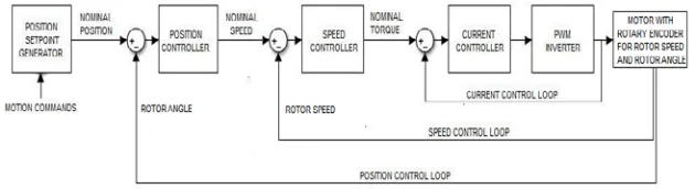
[image:4.595.88.403.386.472.2]A rotational axis drive consists of six major elements; position setpoint generator, position controller, speed controller, direct torque or current controller, three-phase inverter, and motor with rotary encoder for rotor speed and rotor angle. Figure 2 represents the principle of operation of rotational axes.
Figure 2. Block diagram showing the drives operation for rotational axes.
The speed controller, which has as an input the error generated by the difference between the nominal speed produced by the position controller and the actual motor speed received from the attached rotary encoder, produces the torque setpoint command which is applied to the current controller. Speed controller based on a Proportional-Integral (PI) regulator calculates the required torque value. The speed control loop also contains a low-pass filter in order to smooth out the velocity setpoint value, which is received by the position controller.
The current control loop of the studied system, which is implemented using vector control technique, is also known as torque or acceleration control loop due to the fact that, the current control loop aims at controlling the motor electrical torque and machine acceleration. The current controller based on a PI regulator receives the error signal, produced by the difference between the actual current and the nominal torque generated by the speed controller, in order to regulate the motor electrical torque and machine acceleration, which are directly proportional to the motor current.
3
Translation axes
The feed drives from translation axes have two main parts: control (electrical) parts (described in the previous section) and mechanical parts (including the mechanical transmission systems which convert the rotary motion of the motor into linear motion of the nut through the ball-screw assembly driven by the belt drive system). In the case of translation axes, the rotary encoder is used only for rotor speed. The position controller receives feedback signals produced by the linear encoder (mounted on the side) which directly measures the actual position of the orthogonal trimming head. Figure 3 shows the principle of operation of translation axes.
Figure 3. Block diagram showing the drives operation for translation axes.
influenced by these factors. In high precision machining, friction between the moving components of the machine tool, such as ball-screw and nut, may cause serious errors. In most cases, the largest portion of friction, which is produced due to complex kinematics of the ball nut, is undesirable because it causes steady state error. However, in some cases, it might be desirable, because it offers damping [8].
The modelling of axes affected by gravity, which is considered by adding a resistant torque to the motor, is quite different. Thus, for the modelling of Z -axis, the gravity has to be taken into account. More specifically, the torque is constant for a vertical axis, while it depends on the angular axis position for a tilting axis. The friction is always the dominant source of disturbance in axis control. Finally, beneficial damping characteristics and reduction of non-linear behavior, such as backlash can be provided by a pre-loaded ball-screw. Nevertheless, friction will exist, yet [13].
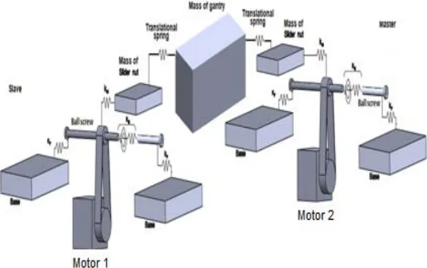
Finally, for convenient control of large mechanisms such as gantry robots, two motors may be required to drive a single axis. This split-axis option has also been adopted by the studied CNC machine tool for the gantry drive. The split-axis feature automatically coordinates the drive of the two motors that receives coordinated commands to keep the mechanism properly aligned.
4
SIMULINK models for rotational axes
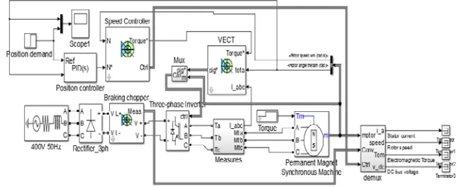
The SIMULINK blocks which compose a CNC machine tool rotational axis drive are a three-phase source ‘400V 50Hz’, a three-phase diode rectifier
[image:6.595.82.404.461.593.2]‘Rectifier_3ph’, a ‘Braking chopper’, a ‘Three-phase inverter’, a ‘Permanent Magnet Synchronous Machine’, a ‘Position controller’, a ‘Speed controller’, and a vector controller ‘VECT’. The SIMULINK model for the rotational axes is depicted in the Figure 4. There is little difference between the B-axis and C -axis drive apart from planetary gearbox and data for the parameters of various elements that have been determined according to their corresponding datasheets and specified in each block’s dialog box.
5
Simulink models for translation axes
As mentioned before, a translation axis is divided into the electrical part and the mechanical part. The control part has been already described in detail in the previous section where it was presented the development of the SIMULINK models for the rotational axes. In this section, the mechanical part including the mechanical transmission system, which converts the rotary motion of the motor into linear motion of the nut using the ball-screw assembly driven by the belt drive system, is built in SIMULINK.
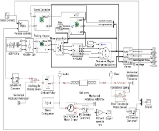
The main blocks which form the mechanical part of CNC machine tool translation axis are a belt drive (gear ratio) ‘Belt and Pulley’, a ‘Ball-screw’,
[image:7.595.90.407.329.591.2]‘Inertia’, ‘Mass’, and a ‘Translational spring’. The SIMULINK model for the single-motor translation axes X and Z is depicted in figure 5. The SIMULINK model for gantry drive includes two single translation axes, due to it has adopted the split-axis feature. The model of controller configuration of X-axis drive is almost the same with that of Z-axis drive. For the mechatronic modelling of Z-axis, the gravity has been taken into account. Nevertheless, data for the parameters of various elements, which have been specified in each block’s dialog box, have been determined according to their corresponding datasheets. Simulation results are shown in [23].
Figure 6 illustrates the block diagram for gantry drive. The elements included in SIMULINK blocks ‘Y1-axis drive model’ and ‘Y2-axis drive model’ are presented in Figure 5. The position controller of gantry drive sends coordinated commands to the speed controllers for Y1-axis and Y2-axis to keep the two axes properly aligned.
Figure 6. Block diagram for gantry drive.
The 3D assembly models are initially built in SolidWorks and imported into SimMechanics which interfaces seamlessly with SimPowerSystems, SimDriveline, and Simulink packages [23]. Figure 7 shows the links between the practical elements of the gantry feed drive.
[image:8.595.93.402.376.570.2]6
Development and implementation of a SIL platform
Sztendel et al. in [18, 22] have described the steps for data acquisition using ControlDesk and HIL implementation of the drive models in dSPACE. SIL applications are prototyping simulations, prepared on a designer’s computer to model the behavior of a real-time control system. SIL part was conducted with the use of the MathWorks software with the model of process automatically generated from the SolidWorks simplified multibody construction assembly. Simulation models are running on in dSPACE 1005 board, where in future compensating calculations can be carried out using FEA models.
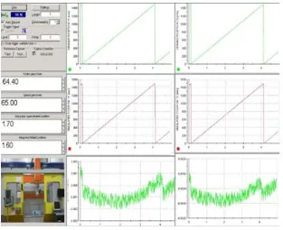
[image:9.595.90.403.273.528.2]An important advantage of a SIL platform is the possibility to directly observe and relate the effective and the measured parameters of the system like position or speed. So the user can adjust the controller parameters in order to obtain the best working conditions. Figure 8 shows the Graphical User Interface (GUI) for the simulation and a picture of the actual machine.
Figure 8. SIL GUI for gantry drive using dSPACE real-time system.
hand middle graph and for Y2-axis in right hand middle graph. The linear positioning error for Y1-axis (see Figure 8 left hand, bottom corner) and for Y2 -axis (see Figure 8 right hand, bottom corner) is the difference between the position demand and the simulated orthogonal trimming head position. Values for the position demand signal were chosen in accordance with the experimental data from the GEISS machine measured linear position using ServoTrace tool. The position demand requests the travel of orthogonal trimming head for the distance of 1500 mm. The errors are around 1 μm, so they show good correlation between demand signals and simulated position values.
7
Conclusions and further work
Machine tool is a complex mechanical and control system. Understanding and accurately modelling each component is hard to achieve. Therefore, we are trying to connect programs into a conventional software-based simulation system.
The paper presents the development and implementation of a SIL platform allowing the real-time simulation of the hybrid model of the gantry axis for the CNC machine tool feed drive. The graphical model for the gantry axis of the GEISS machine has been developed using SIMULINK. The next step is to develop Hardware-in-the-loop platform (HIL) where the experimental data obtained from the SINUMERIK 840d SL controller using servo trace and the simulated data can be compared. This would confirm the usability of the developed SIL model in the HIL platform.
Using SIL simulation systems, the model of the machine controller, SimMechanics models for mechanical elements and SIMULINK models for feed drives has made possible to reproduce accurately the range of movement of the tool. This approach provides a test environment offering modelling support for dynamic environments that may reduce significant cost within the NC controller design and trainings. Simulation reduces valuable machining capacity, there is no risk of damaging equipment by using manual inputs and space required is much lower.
References
[1] Pislaru C 2001 Parameter Identification and Hybrid Mathematical Modelling Techniques Applied to Non-linear Control Systems (Doctoral Thesis), University of Huddersfield, Huddersfield
[2] Pislaru C, Ford DG and Moreno-Castaneda VY 2005 Proc.
LAMDAMAP 2005 (Cranfield, UK), pp 220-229
[4] Erkorkmaz K and Altintas Y 2001 Int. J. of Machine Tools & Manuf.
vol 41, pp 1487–1509
[5] Erkorkmaz K, Altintas Y and Yeung CH 2006 Annals of CIRP, vol 55, pp 399-402
[6] PislaruC, Ford DG and Holroyd G 2004 Proc. IMechE, I vol 218, pp 111-120
[7] Pislaru C, Ford DG and Myers A 2006 Proc. EUSPEN 2006 (Baden bei Wien, Austria), pp 147-150
[8] Widiyarto MHN, Pislaru C, Ford DG, Longstaff AP and Myers A 2005 Proc. of the 7th LAMDAMAP, pp 454-463
[9] Shokry H and Hinchey M 2009 Computer vol 42, pp 53–59
[10] Pürzel F, Klimant P, Wittstock V and Kuhl M 2013 Int.Conf. on Virt. and Augmented Reality, pp 98–107
[11] Plummer A 2006 Proc. of the IMechE, I vol 220, pp 183–199
[12] Chae H, Jin X, Lee S and Cho J 2009 Commun. in Comp. and Inf. Sc.vol 59, pp 204–212
[13] Zaeh F and Poernbacher C 2008 Prod. Eng. Res. Devel. vol 2, pp 39– 46
[14] Pislaru C 2013 Int. J. Mech. Eng. vol 2, pp 39-44
[15] Pislaru C, Ford DG, Sztendel S and Myers A 2009 Proc. 9th
LAMDAMAP (Brunel University, UK), pp 138-146
[16] Sztendel S and Pislaru C 2008 SCE Research Fest. (Huddersfield)
[17] Pislaru C, Sztendel S, Ford DG and Myers A 2008 MATAR (Prague University), pp 25-30
[18] Sztendel S, Pislaru C, Poxton A, Ford DG and Myers A 2009
Proc. 9th LAMDAMAP (Brunel University, UK), pp 147-155
[19] Dougal R, Monti A, Pettus B and Santi E 2000 Int. Workshop on Virt. and Intel. Measur. Syst., (Annapolis, MD, USA)
[20] Sztendel S, Pislaru C, Longstaff AP, Ford DG, Myers A and Poxton A 2010 SCE Research Fest. (Huddersfield)
[21] Sztendel S, Pislaru C, Ford DG and Myers A 2008 MATAR (Prague University), pp 123-128
[22] Sztendel S, Pislaru C, Longstaff AP, Fletcher S and Myers A 2012 J. of Phys. Conf. Ser 364, 012091
[23] Papananias M, Sztendel S and Pislaru C 2015 Proc. of11thInt. Conf. LAMDAMAP 2015, (University of Huddersfield, UK), to be published [24] Prevost D, Lavernhe S and Lartigue C 2010 J. of Mach. Eng., High
![Figure 1. Hardware and SIL simulation [13].](https://thumb-us.123doks.com/thumbv2/123dok_us/317971.1032866/3.595.137.356.397.531/figure-hardware-and-sil-simulation.webp)