University of Huddersfield Repository
Xu, Qian, Xu, Zhijie and Holder, Marcus
Predicting specific gravity and viscosity of levelofdetail control in hybrid rendering application.
Original Citation
Xu, Qian, Xu, Zhijie and Holder, Marcus (2009) Predicting specific gravity and viscosity of level
ofdetail control in hybrid rendering application. In: Proceedings of Computing and Engineering
Annual Researchers' Conference 2009: CEARC’09. University of Huddersfield, Huddersfield, pp.
7681. ISBN 9781862180857
This version is available at http://eprints.hud.ac.uk/id/eprint/6865/
The University Repository is a digital collection of the research output of the
University, available on Open Access. Copyright and Moral Rights for the items
on this site are retained by the individual author and/or other copyright owners.
Users may access full items free of charge; copies of full text items generally
can be reproduced, displayed or performed and given to third parties in any
format or medium for personal research or study, educational or notforprofit
purposes without prior permission or charge, provided:
•
The authors, title and full bibliographic details is credited in any copy;
•
A hyperlink and/or URL is included for the original metadata page; and
•
The content is not changed in any way.
For more information, including our policy and submission procedure, please
contact the Repository Team at: [email protected].
PREDICTING SPECIFIC GRAVITY AND VISCOSITY OF
LEVEL-OF-DETAIL CONTROL IN HYBRID RENDERING APPLICATION
Qian Xu1, Zhijie Xu1 And Marcus Holder1
1 University of Huddersfield, Queensgate, Huddersfield HD1 3DH, UK
ABSTRACT
This paper presents the hybrid rendering-based Level-of-Detail (LOD) node which aims to simplify the volume visualization workload to improve the interactive rate of the hybrid rendering programming paradigm. This node utilizes a replacement to provide object-level optimization in between volume and surface models. The indicator for the replacement in the node is based on the distance between viewpoint and the object, or based on the various interaction types in the simulation. Conclusions indicate that the hybrid rendering-based LOD node will improve the interactive rate of hybrid rendering application.
Keywords Level-of-Detail node, replacement, hybrid rendering application
1 INTRODUCTION
In the last two decades, volume rendering and visualization technologies have been widely used in academic research and industrial applications due to their potential to provide direct access to the internal structure of a 3D object (Drebin et al (1988), Levoy (1988), Sar-Dessai et al (2003), Engel et al (2004)). They can be applied into rapid prototyping in virtual manufacturing and medical imaging, even astronomical and atmospheric simulations (Zhang et al (2001), Romeiro et al (2006)). In order to provide better accuracy and visual quality for these applications the volume data size has rapidly increased due to the higher frequency of initial sampling techniques (Bernardon et al (2006)). As the data size increases for high-resolution results, there is an increasing need to improve the interactive rate of volume visualization and manipulation in a complex 3D scene. With the development of modern graphics hardware and the maturing methods for accelerating volume-based operations, real-time human interaction with complex volume models on consumer grade PC hardware has become a research hot-spot in the last decade (Roettger et al (2003), Agus et al (2004), Hadwiger et al (2006)).
Although there has been rapid development of personal grade computer hardware such as dedicated graphics cards, the heavy demands on processing capacity for interactive volume rendering are still to be met. Besides complex calculations, the increasing volume data size has further deteriorated this situation. For example, the size of a volume model for a commonplace object is often at the scale of GB (giga-byte) and multi-object 3D scenes with complex organic volumes can quickly accumulate to TB (tera-byte). In order to reduce the calculation workload in volume rendering and visualization, the research focuses on the investigation of various methods which optimize the rate of utilizing volume model (data) and its relative visualization (Akiba et al (2006), Bernardon et al (2006)). In this research, a hybrid rendering framework has been carried out to improve the efficiency and effect of the complex virtual environment (VE)-based application by integrating volume and surface models into a unified framework. As a functional node of this framework, a new transformation between different models is used to facilitate the complex volume-based operations and manipulations.
Section 2 of this paper provides a brief review on the conventional rendering techniques. In Section 3, we describe work related to LOD investigation. The mechanism and an example of hybrid rendering-based Level-of-Detail node are introduced in Section 4. Section 5 concludes the research with observations on future development.
2 RESEARCH BACKGROUND
Surface Modelling and Visualization
which are often generated from scientific computations, most surface models are “defined” by various geometric modelling tools such as Auto CAD, ProEngineer or the entertainment-oriented 3D Studio Max.
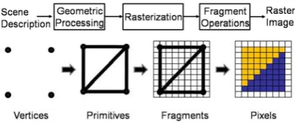
The process for visualizing a 3D surface model using a 2D display device has encompassed a wide area of research into computational geometry, computer graphics, display devices etc. over the last half-a-century. Figure 1 gives a grossly simplified diagram of the key processes involved in this visualization.
As indicated in the diagram, the key stage to turn 3D entities (vertices) into 2D ones (fragments) is the so-called “geometric processing”, which if divided further will see the linear algebra-based transformation from the single model-based “Model Space” to the multiple model-based “World Space” (Sar-Dessai et al (2003)). The intermediate results will then be transferred into the “Camera/View Space” for interactive applications; and finally to the “Projection Space” for casting the objects’ silhouettes in the form of the short 2D lines (rasterized fragments) which are then processed further before being turned into visible images. As shown in Figure 1 in the transformation, from fragments to pixels, various fragment-based operations are applied, such as texture mapping, occlusion testing, stencil testing. Such operations are vital for the ultimate quality of the final display.
Volume Model and Rendering
Compared to surface modelling and its visualization approach, volume rendering requires more complex operations. It involves the configuration of volume models and the selection of their processing tactics. There are several common volume model data formats such as “raw”, “img” and “hdr” for storing volume data. These formats are often used by specially designed industrial cameras, medical scanners, and even astronomical telescopes. Among those formats, the most popular one is the “raw”, which fulfils the same role as film negatives in traditional chemical photography (Engel et al (2004)).
The essential and basic element of volume models is the so-called voxel – the acronym for volume pixel. According to the choice of different optical models for filtering and integrating voxel information, a volume model can be rendered in various modes (Stegmaier et al). The basic theory is to calculate each voxel’s colour and transparency and use this to inform the rendering of the final image.
In Direct Volume Rendering (DVR), the voxel is used to store the discrete volume data and arrange it in the so-called proxy geometries (Sar-Dessai et al (2003)). Depending on the type of the proxy geometries used, the volume model can either be presented in a single 3D block referred to as view-aligned slices or can be split up into three stacks of 2D slices known as object-aligned slices (Sar-Dessai et al (2003), Weiskopf et al (2003), Engel et al (2001)). In contrast to DVR, Indirect Volume Rendering (IDVR) which is another branch of volume rendering strategies focuses on creating optical models by combining many iso-surfaces extracted from the volume data set to form the outer shape of the volume.
In DVR, after establishing the optical model, each voxel involved in calculation will be converted into color and translucent entities through classification. The theory of classification is to transform scalar voxel values into color indices through pre-defined look-up tables (Engel et al (2004)). Although the original voxel scalar values might stand for density, temperature or intensity, they will all be converted into corresponding colour and translucency values which are integrated through specified processes.
Volume rendering differs from the projection process in surface rendering by utilizing the ray casting technique (an image-order direct volume rendering algorithm) to “fill” the pixels on the image plane. Ray casting casts a configurable number of parallel rays through the optical model in its model space (Stegmaier et al (2005)) in one of two viable directions. One is the so-called back-to-front (from object space to image space) process; another follows the front-to-back order (from image space to object space). As indicated in Figure 3, each ray is cast into the model space and intersects with a group of voxels along the line. The corresponding optical properties obtained from the encountered voxels will be integrated along the ray to be projected as the image.
The pixel-based operation on image plane in volume rendering is similar to the surface pipeline, which will be discussed in detail in Section 3. A simple illustration of the volume rendering pipeline is shown in Figure 3.
3 RELATED WORK
can accelerate the speed of rendering by reducing the workload on graphics pipeline stages. LOD algorithms for 3D computer graphics can be traced back to an article that originally appeared in the October 1976 issue of Communications of the ACM by James H. Clark (Clark (1976)).
Benefiting from the idea of this traditional polygonal LOD node, the first idea of volume-based LOD was described in 1989 (Cullip et al (1989)) and an improved one was carried out in 2000 (Weiler et al (2000)). In volume visualization, the voxel which has a zero value will not be displayed on the image plane (Sar-Dessai et al (2003)). Based on this, they carried out a novel strategy which makes the relative float values multiply zero to “delete” some voxels to reduce the visualization workload. In order to restore the volume model, Sar-Dessar carried out the resolution to obtain these “deleted” voxels’ values by calculating their neighbours’.
However, artefacts cannot be ignored in this transformation. For example, the boundary of virtual engine’s broken part will be blurred in this LOD. Because the volume model cannot reveal the internal structure of an object at a large distance, the surface of the virtual engine can be rendered in surface modelling mode. A surface model is used to replace volume one as the viewpoint moves away from the viewer. This replacement can avoid artefacts and blurring the interactive rate and the efficiency of this simulation can be improved at the same time.
4 HYBRID RENDERING-BASED LOD NODE
In this hybrid rendering-based LOD, a surface model is used to facilitate the manipulation and external visual representations of objects, and a volume model is utilized to carry out various internal operations on the object. The key of the hybrid rendering-based LOD node is to threshold the special “points” for replacement, i.e. based on the distance between the viewpoint and the object. In the 3D coordinate system, the special “points” will form a virtual spherical surface which is shown in Figure 4. In order to be distinguished from the origin (O) of this coordinate system, the object is denoted by target (T).
Two 3D coordinates (
V V V V
(
x,
y,
z)
) and (T T T T
(
x,
y,
z)
) are respectively defined to represent the viewpoint and the target. The distance between them can be written as
(
)
(
)
(
)
22 2
V x x y y z z
R
=
V
−
T
+
V
−
T
+
V
−
T
(1)A constant value
R
T is predefined as a standard distance. By comparingR
V withR
T, we can summarize the two relationships,(If the Viewpoint comes into the spherical field)
R
T<
(
V
x−
T
x)
2+
(
V
y−
T
y)
2+
(
V
z−
T
z)
2 (2) and(If the Viewpoint comes out of the spherical field)
R
T≥
(
V
x−
T
x)
2+
(
V
y−
T
y)
2+
(
V
z−
T
z)
2 (3)Based on this indicator, object-level optimization in between volume and surface models can be carried out.
According to the results of comparison between
R
VwithR
T, the volume and surface models will berespectively set as active or passive (the results are shown in Figure 5).
5 CONCLUSIONS AND FUTURE WORK
The hybrid rendering node devised in this research has been implemented using OpenGL and OpenSG APIs in a VC++ programming environment. The host PC was an Intel Core2 2.40GHZ CPU with 2G RAM.
In this project, some elements of the future VE-based application will be obtained by loading existing models. These models are freely created without fixed requirements for size and scale and they may need to be modified after being loaded. For instance, a virtual lathe may be twice as large as the defined virtual workshop after being loaded into a virtual environment. The prime idea of designing an adjustable scale node is to adjust the size of these models.
In order to manage the different sizes of models, the scale node was carried out to change the scale of an object in X-, Y- or Z-axis proportionally. In Figure 6, the sizes (x, y and z) of volume or surface model are
multiplied by a pre-defined value (s) in scale node. By adjusting this value, the model can be enlarged or retrenched in X-, Y- or Z-axis. Benefiting from the idea of conversion in volume-based LOD (Weiler et al (2000)), by attaching an adjustable scale node on volume and surface models respectively, the new replacement can be carried out by making the scales of object multiply by zero in X-, Y- and Z-axis, i.e. the sizes of volume and surface models are all controlled by the same scale node. The effects of keeping all scales at zero (or one) are similar to those of setting models to passive (or active).
However, the current adjustable scale node can only modify the size of a “defined” model, i.e. the objective of the scale node is fixed at the application runtime. Although the scale node can be set on each element to overcome this problem, the efficiency and the practicability of the application will be badly restricted. In order to solve this problem, future research will begin by enabling the scale node to change the objective during the application by investigating the information provided by using the mouse to orient the object.
REFERENCES
Agus M., Giachetti A., Gobbetti E., Zanetti G. and Zorcolo A. (2004), Hardware-Accelerated Dynamic Volume Rendering for Real-Time Surgical Simulation. In Proceeding of Workshop Virtual Reality Interactions and
Physical Simulations (VRIPHYS '04).
Akiba H., Fout N. and Ma K. L. (2006), Simultaneous Classification of Time-varying Volume Data based on the Time Histogram. In Euro graphics/IEEE VGTC Symposium on Visualization, pp.171-178.
Bernardon F. F., Callahan S. P., Comba J. L. D. and Silva C. T. (2006), Interactive Volume Rendering of Unstructured Grids with Time-varying Scalar Fields. In Euro graphics Symposium on Parallel Graphics and Visualization, pp.51-58.
Clark J. H. (1976), Hierarchical Geometric Models for Visible Surface Algorithms. Communications of ACM,”
Vol.19, No.10, pp.547-554.
Cullip T. J. and Neumann U. (1989), Accelerating Volume Rendering with 3D Texture Mapping Hardware.
Technical report TR93-027, Department of Computer Science, University of North Carolina.
Drebin R. A., Carpenter L. and Hanrahan P. (1988), Volume Rendering. In ACM SIGGRAPH Computer
Graphics, Vol. 22, No. 4, pp.65-74.
Engel K., Hadwiger M., Kniss J. M., Lefohn A. E., Salama C. R. AND Weiskopf D. (2004). Course Notes: Real-Time Volume Graphics, Course #28. In SIGGRAPH 2004.
Engel K., Kraus M. and Ertl T. (2001), High-Quality Pre-Integrated Volume Rendering Using Hardware-Accelerated Pixel Shading, In Proc. Eurographics/SIGGRAPH Workshop on Graphics Hardware, pp.9-16.
Hadwiger M., Kratz A., Sigg C. And Bϋhler K. (2006), GPU-accelerated Deep Shadow Maps for Direct Volume Rendering. In SIGGRAPH/EUROGRAPHICS Conference on Graphics Hardware, pp.49-52.
Levoy M. (1988), Display of Surface from Volume Data. In IEEE Computer Graphics and Applications, Vol. 8,
No. 3, pp.29-37.
Roettger S., Guthe S., Weiskopf D., Ertl T. and Strasser W. (2003), Smart Hardware-accelerated Volume Rendering. In ACM International Conference Proceeding Series, Vol.40, pp.231-238.
Sar-Dessai S. and Botsch M. (2003), The Lecture Notes on Computer Graphics I. The lecture held by Prof. Dr. Leif Kobbelt at RWTH Aachen.
Stegmaier S., Strengert M., Klein T. and Ertl T. (2005), A Simple and Flexible Volume Rendering Framework for Graphics-Hardware-based Raycasting, In Proceedings of Volume Graphics '05, Stony Brook, New York,
USA, pp.187-195.
Weiler M., Westermann R., Hansen C., Zimmerman K. and Ertl T. (2000), Level--of--Detail Volume Rendering via 3D Textures. In Proceeding of IEEE Volume Visualization, pages.7-13.
Weiskopf D., Engel K. and Ertl T. (2003), Interactive Clipping Techniques for Texture-Based Volume Visualization and Volume Shading, In IEEE Transactions on Visualization and Computer Graphics, Vol. 9,
No. 3, pp.298-312.
Zhang S., Demiralp C., Keefe D. F., Basser P. J. and Chiocca E. A. (2001), An Immersive Virtual Environment for DT-MRI Volume Visualizations: A Case Study. In Proceedings of the conference on
Visualization '01, Session C2, pp.437-440.
Figure 1: The surface model rendering pipeline
R T
View point
R v Target R T
View point
R v Target
[image:6.595.176.387.305.394.2]Figure 4: The design of indicator in LOD switching Figure 3: Volume rendering pipeline
Figure 5: The results of hybrid rendering-based LOD node
[image:7.595.106.485.352.526.2]