ISSN 2250-3153
www.ijsrp.org
Implementation of MATLAB based object detection
technique on Arduino Board and iROBOT CREATE
Raquib Buksh
1, Soumyajit Routh
2, Parthib Mitra
3, Subhajit Banik
4, Abhishek Mallik
5, Sauvik Das Gupta
61234
Department of Electrical and Electronics Engineering, West Bengal University of Technology, Kolkata, WB, India 56
School of Electrical and Computer Engineering, Oklahoma State University, Stillwater, OK, USA
Abstract –This paper illustrates the application of the color detection technique using MATLAB algorithms, to control the state of the output pins of an Arduino (AT mega 328) and also to control the movements of an iROBOT CREATE [1]. This gives a very small example of implementing Bounding Box algorithm [2] and use of the simple color detection technique and other ‘REGIONPROPS’ [3][4] parameters we can control the outputs of an Arduino board [5]and also control an iROBOT CREATE.
Keywords – Color detection, MATLAB, iROBOT CREATE, Arduino AT Mega 328, Bounding box.
I. INTRODUCTION
n this paper, we are going to take advantage of the Bounding Box technique, present in image processing tool box [6], to detect the centroid of a particular colored image, and the change of the centroid co-ordinates will be detected, which will be applied to generate different commands. These commands would be fed to an Arduino to change the states of its output pins, and, to control the movement of an iROBOT CREATE in a particular direction. Here same logic has been implemented for both Arduino (AT mega 328) and iROBOT CREATE.
The main algorithm that is implemented is very simple and robust. A camera takes continuous snapshots and a particular colored region (predefined by user) of the images are bounded by a box. Then an algorithm is written that will sense the movement of the colored box and generate different commands, each command corresponds to movements in a particular direction of an iROBOT CREATE(that is fed wirelessly to the robot) or state change of certain output pins of an Arduino.
Arduino is basically an open source platform which is very easy to use, and, interfacing with Arduino is simple. The iROBOT CREATE that has been used is a programmable robot developed under Roomba platform in 2007, explicitly designed for robotics development.
II.HARDWARE PLATFORM
A. Imaging device
The web cam is used as image capturing device. Here the device takes snapshots continuously after a predefined very short interval of time. Due to human’s perception of vision these snapshots taken within a very short period of time and displayed continuously might look as a continuous image i.e. video. Depending on the processing speed of the computer being used, this interval for taking snapshots is adjusted.
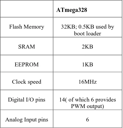
B. Arduino ATmega328
Arduino Atmega328 is used. The image of an Arduino board is shown in Figure 1(a) and the pin diagram is shown in Figure 1(b) which will help to know the detailed hardware configurations of the Arduino board used.
Arduino is an open-source electronics prototyping platform based on flexible, easy-to-use hardware and software. Arduino can programmed according to users own need. The power supply can be via USB or external power supply. The power source is selected with a jumper, a small piece of plastic that fits onto two of the three pins between the USB and power jacks. There is sufficient number of pins for
(a)
ISSN 2250-3153
www.ijsrp.org
(b)
Figure 1(a): Actual Arduino image, Figure 1(b): Arduino pin settings
ATmega328
Flash Memory 32KB; 0.5KB used by
boot loader
SRAM 2KB
EEPROM 1KB
Clock speed 16MHz
Digital I/O pins 14( of which 6 provides
PWM output)
[image:2.612.56.283.60.237.2]Analog Input pins 6
Table 1: Specifications for our Arduino
both analog and digital. Before programming is done on
Arduino, the board used has to be selected (AT mega 328) from the ‘tools’ option of Arduino software. Serial port
(COM1/COM2/COM3) in use has to be selected also from the ‘tools’ menu. The platform is then set for programming. After the desired code is written it has to be uploaded to the microcontroller of the Arduino and then Arduino is expected to work as desired.
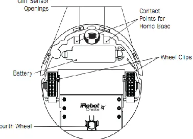
C. iROBOT CREATE
‘iROBOT CREATE’ is a robot manufactured by
‘ iROBOT’ that is based on the Roomba platform and was introduced in the year 2007.The iROBOT CREATE includes a cargo bay which houses a 25 pin port that can be used for digital and analog input and output. The CREATE also possesses a serial port through which sensor data can be read and motor
commands can be generated using the "iROBOT Roomba Open Interface protocol"(a MATLAB based function dedicated to control iROBOT CREATE).
In order to control the ‘iROBOT CREATE’ using MATLAB a toolbox named ‘iROBOT CREATE toolbox’ has to be used that is not present in MATLAB. The iROBOT CREATE simulator is a MATLAB toolbox designed to visualize the robot's movement in different environments. The user can control the robot manually, or by writing a program for autonomous behavior. The simulator is designed to accept autonomous programs written using the MATLAB Toolbox for the iROBOT CREATE (by Esposito and Barton) [7], thus allowing for seamless transitions between simulation and physical execution.
Figure 2(a)
Figure 2(b) Figure 2(c)
[image:2.612.320.545.253.704.2] [image:2.612.344.532.257.433.2] [image:2.612.65.271.275.490.2]ISSN 2250-3153
[image:3.612.313.558.52.201.2]www.ijsrp.org Figure 2 shows the detailed hardware of the iROBOT that we are
going to control using our MATLAB programming.
D. Bluetooth Adaptor Module (BAM)
Commands can be sent to the iROBOT either via wire or wireless medium (via Bluetooth or Wi-Fi or Serial Wired Communication). Here it is done wirelessly, by using a Bluetooth device connected to the iROBOT and then interfacing it with the computer’s Bluetooth. For this purpose a Bluetooth Adaptor Module or BAM is used. The Element Direct BAM (Bluetooth Adapter Module) enables wireless control of the iROBOT CREATE from any Windows, Mac or Linux computer, or any other Bluetooth enabled device. The BAM connects to the
CREATE's cargo port to CREATE a virtual serial port. The BAM is a wireless serial cable replacement that uses the Serial Port Profile (SPP) to provide a means to send and receive serial packets to the iROBOT CREATE mobile robot. The BAM allows the CREATE robot to be driven remotely with a PC hosted web server. It also allows user to run complicated algorithms on a host computer and communicate with the iROBOT in real time. The various specifications of the BAM is mentioned in Table 2 and Table 3.
Bluetooth Specifications
Device Name Element Serial
Available Services SPP
RF power Class 1 Bluetooth
Baud rate 57600
Data Bits 8
Stop Bits 1
Table 2: Specifications for our BAM
General Specifications
Operating Frequency 2.4GHz
Voltage 5V
Current 100 mA maximum
Internal Antenna Multilayer Chip, Peak gain
0.5dBi
Operating range 91 meters
Operating temperature 0 to 50 degree centigrade
[image:3.612.382.513.241.392.2]Size 55x55x16mm
Table 3: General Specifications for our BAM
Figure 3: Bluetooth Adaptor Module (BAM)
III. METHODOLOGY
The whole process can be divided into two parts. The first part being detection of the movements of the colored box using MATLAB image processing and the second being interfacing with the Arduino and the iROBOT CREATE to act accordingly.
A. Movement detection using MATLAB
Image acquisition is a crucial part for movement detection. To get the detail of the hardware device interfaced for imaging ‘imaqhwinfo’ command is used. Here ‘winvideo’ is a dedicated adapter for windows platform. Now it is possible that more than one imaging device is connected to the computer, to avoid this problem while taking snapshot from an imaging device its serial number is also mentioned. It is possible to take finite and infinite numbers of snapshot from the imaging device according to the requirement of the user. Now ‘BoundingBox’ algorithm is applied on the captured images.
The Bounding Box is a part of ‘regionprops’ function. The brief algorithm of ‘BoundingBox’ is explained below:
[image:3.612.62.251.247.384.2] [image:3.612.34.284.504.666.2]ISSN 2250-3153
www.ijsrp.org Run this image grabbing function inside a loop( while
loop is recommended)
From the required color index, perform image
subtracting function.
Apply median filter for noise cancelation and convert the image into black and white image as most of the image processing tool cannot be applied on color image.
Calculate the ‘regionprops’ of each of the component of
the image that is a function of MATLAB by which all details of the component of the image can be enlisted.
REGIONPROPS: Measure the properties of any particular image region.
STATS = REGIONPROPS (BW, PROPERTIES) measures a set of properties for each connected component (object) in the binary image BW, which must be a logical array, it can have any dimension.
STATS are an array of structures with length equal to the number of objects in BW, CC.NumObjects, or max (L(:)). The fields of the structure array denote different properties for each region, as specified by PROPERTIES.
PROPERTIES can be a comma-separated list of strings; a cell array containing strings; the string 'all'; or the string 'basic'.
Shape Measurements:
'Area, 'EulerNumber', 'Orientation', ‘BoundingBox’, 'Extent' 'Perimeter','Centroid', 'Extrema’,'PixelIdxList’,'ConvexArea'
'FilledArea',‘PixelList’,'ConvexHull’,'FilledImage’,'Solidity' 'SubarrayIdx' , ' Eccentricity',' MajorAxisLength',
'EquivDiameter' 'MinorAxisLength'.
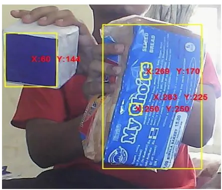
[image:4.612.334.556.50.240.2]In this project mainly three shape measuring function are used, they are bounding box, centroid, and area. Using the bounding box concept the red, blue or the green portions can be identified and at the same time the centroid of the detected portion can also be displayed.
Figure 4: Bounding box showing the centroid.
Now tracking the centroid of the bounded region, the remaining program is executed. The main procedure is as follows:
The difference or change in centroid of the object between two consecutive snapshots is noted.
When an individual holds the colored object in front of
the camera and as he gradually moves his hand from left to right(so does the centroid), his hands also move slightly up and down(due to shaking of hand, which is unintentional). So the change of centroid will be in both the axes (x and y), but movement in one particular direction is considered. For this reason one particular axis(x or y) where movement is greater is taken under consideration and it is regarded as the intentional movement of the user.
Now after recognizing the axis in which the movement
is intended, the direction of change is noted, i.e., whether it is positive or negative movement in that particular axis and a command corresponding to it is generated.
After these above two steps, the generated command is
fed to the input of an Arduino and the iROBOT.
B. Interfacing with Arduino and iROBOT
1) Arduino Interfacing: Arduino windows based software is used to program the microcontroller on the board. Arduino can be connected through Universal Serial Bus. In the software Interface firstly model name of the Arduino is selected. Embedded C program is used for programming the microcontroller. Arduino programming has a pre-defined pattern, there are three parts, declaring the variables, setup part (communicational command) and loop part. As per the name suggests variable declaring part initializes all the variables which are needed throughout the
program. Setup part consists of communication port
ISSN 2250-3153
www.ijsrp.org Then bounding box program is applied to detect the colored box
movement, and for a particular movement a particular LED glows (as a particular pin goes High). For this purpose two programs have to be executed. The first one is in the MATLAB and the second in Arduino.
In the MATLAB program the bounding box concept is used to detect red, blue or green component. Then for a particular movement in x and y axis a character (a command) is send to the Arduino board using ‘fprintf’. For example if the movement in x is positive then character ‘r’ is sent, meaning right. And if it is negative movement character ‘l’ can be sent, meaning left. Similarly for the y axis ‘f’ and ‘b’ for forward and backward movement can be sent respectively, One can send any character for any condition, according to his own choice
When from MATLAB the Arduino receives particular character via Universal Serial Bus, it is needed to be programmed to act according to a users need. Here there are four LEDS to four different Arduino pins. For four different box movements(right, left, up and down) MATLAB send the Arduino four different characters as commands and the programmed Arduino receives those commands and operates to set one out of four pins to HIGH and all the other three to LOW simultaneously. In this way movements of the box in a particular direction can be sensed by glowing a particular LED representing a definite direction.
2) iROBOT Interfacing: iROBOT is interfaced with computer wirelessly. For this purpose Bluetooth Adapter Manger (BAM) is connected to the cargo bay of the iROBOT.
After completing the Bluetooth setup the MATLAB program is executed. The iROBOT is accessed via Bluetooth.
The main idea of movement control of iROBOT is the same as that of glowing a LED tracking the box’s movement using Bounding Box technique. For forward and backward movement y axis change is considered and for the left and right turning x axis change is considered.
IV. DISCUSSIONS AND CONCLUSION
The main aim of the project was to detect the colored box’s movement and how that can be applied to control the movement of the iROBOT CREATEs. Since using MATLAB image processing red, green or blue color can be detected and MATLAB bounding box algorithm provided access to its centroid, it became easy to detect the hand movement of the person holding any of red, green or blue colored object in his hand and thereby controlling either an Arduino or iROBOT.
There are certain aspects of the paper that needs to be worked upon and improved. Those aspects include eliminating unwanted detection of color while execution of Bounding Box algorithm except the target object, multiple color detection other than red, green and blue .
The iROBOT CREATE can move left, right, front and backwards, but more detailed studies is to be done to rotate it in intermediate angles using the box movement more accurately.
In summary, this paper implies how hand movements can be implemented to control any robot using color detection technique. MATLAB provides easy methods for doing that. Moreover the interfacing between MATLAB and other external hardware devices such as Arduino and iROBOT, makes the work much easier.
ACKNOWLEDGMENT
This work was supported by ESL (www.eschoollearning.net), Kolkata.
REFERENCES
[1] Jason T. Isaacs, Daniel J. Klein, Joao P. Hespanha in
‘A Guided Internship For High School Students Using iROBOT CREATE’. Department of Electrical and Computer Engineering, University of California, Santa Barbara, CA 93106 USA(e-mail:fjtisaacs,djklein,[email protected]).
[2] V. Subburaman and S. Marcel. Fast Bounding Box estimation based face detection in ‘Workshop on Face Detection of the European Conference on Computer Vision (ECCV)’, 2010.
[3]http://nf.nci.org.au/facilities/software/Matlab/toolbox/images/regionpr ops.html
[4] http://www.mathworks.in/help/images/ref/regionprops.html
[5]http://arduino.cc/en/Tutorial/HomePage
[6]http://www.mathworks.in/help/images/index.html