Modeling and Simulation of Photovoltaic Cell Using
Matlab/Simulink
Nisha Sharma
*, Dr. Fahim Ansari
**, Pawan Kr. Panday
****
P.G. Student, Conrol & Instrumentation, BRCM College of Engineering & Technology, India
**
Head of EEE Department BRCM College of Engineering & Technology, India
***
Assistant professor EEE Department BRCM College of Engineering & Technology, India
Abstract- This paper presents modeling of Photovoltaic (PV) module using MATLAB/Simulink. The model is developed on the basis of mathematical model of the PV module. The PV module of VIKRAM SOLAR PANEL PV- ELDORA 230 is selected for the experimental and technical data to analyze the developed model. The objective of this paper is to develop a model to simulate the behavior of a photovoltaic cell. Both models are implemented in MATLAB/Simulink. To demonstrate the validity of the model the IV and PV curves results were compared with those provided by the manufacturer.
Index Terms- Photovoltaic (PV), PV cells, Modeling, Simulation, MATLAB/Simulink, IV curves.
I. INTRODUCTION
he entire world is facing a challenge to overcome the hurdle of energy crisis. The diminishing deposits of non renewable energy resources such as coal, natural gas, fossil fuels etc. have added to this worry. It is thus fairly evident that a need exist for developing alternative energy sources. The immediate need would be to vitiate the problems caused by depletion of oil and natural gas, while the long term need would be to develop means that can replace coal and fossil fuels. Rapid population growth and industrialization, demands for an increased amount of electrical energy[1]. Solar energy is a renewable, inexhaustible and ultimate source of energy. If used in a proper way, it has a capacity to fulfill numerous energy needs of the world. Solar cells convert solar energy into electrical energy. This phenomenon occurs in materials which have the property of capture photon and emit electrons. The main material used in the photovoltaic industry is silicon [2]. But there are many lines of research to find materials to replace or supplement to silicon to improve conversion efficiency, as for example [3, 4].
The main aim of this paper is to provide a reader with the fundamental knowledge on design and building the blocks of PV module based on the mathematical equations using MATLAB/ Simulink. The principle and operation of the PV cell and the fundamental characteristics of PV cell are discussed in chapter II. In chapter III mathematical model of the ideal PV cell and also the practical PV cell values are shown from VIKRAM SOLAR PANEL- ELDORA 230 .In chapter IV the different types of models are shown which are analyzed during this work. The simulation model developed using MATLAB/Simulink and the results obtained are presented and discussed in chapter 5.
II. OPERATION AND CHARACTERISTICS OF PV OR SOLAR CELLS
2.1Principle of Operation of Solar Cell:
Solar cell is basically a p-n junction fabricated in a thin wafer or layer of semiconductor. The electromagnetic radiation of solar
energy can be directly converted to electricity through photovoltaic effect. Being exposed to the sunlight, photons with
energy greater than the band-gap energy of the semiconductor are absorbed and create some electron-hole pairs proportional to
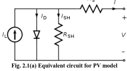
the incident irradiation. Under the influence of the internal electric fields of the p-n junction, these carriers are swept apart and create a photocurrent which is directly proportional to solar insolation [5]. The ideal solar cell, theoretically, can be modeled as a current source in anti-parallel with a diode (Fig.2.1 (a)). The direct current, generated when the cell is exposed to light, varies
linearly with solar radiation. An improvement of the model includes the effects of a shunt resistance and another in series [6].
Fig. 2.1(a) Equivalent circuit for PV model
According to [6] and based Fig. 2.1(a) photovoltaic panel its characteristic equation :
I = I ph – Id – Ish ….(1)
Being Iph, Id and Ish:
Iph= . ...(2)
Id=Is.( -1) ….(3)
Is=Isc.( -1) ….(4)
Vt= ....(5)
[image:1.612.334.552.418.541.2]reverse saturation current. RS and Rsh are inherent resistances in series and parallel associated with the cell. Q is the electron charge, K Boltzmann‟s constant and a, the ideality factor modified.
2.2 Characteristics of Solar Cell:
PV system naturally exhibits a nonlinear I-V and P-V characteristics which vary with the radiant intensity and cell temperature. Fig.2.1 (b) and Fig.2.1(c) respectively shows the equivalent circuit models of cell.
Fig. 2.1(b) I-V curve
The curve drawn (Fig. 2.1(b) and Fig.2.1(c)) shows how the voltage and current varies with Irradiation and Temperature of PV module. We can find out maximum power by finding out the Vmax and Imax. There are different methods of finding out
Maximum power of PV module i.e. Pmax and these are known as
MPP Techniques i.e Maximum Power Point Technique at that point we get Vmax and Imax.
Fig. 2.1(b) P-V curve
The fundamental parameters related to solar cell are short circuit current (Isc), open circuit voltage (Voc), maximum power point (MPP)[6].
Short Circuit Current is the current corresponds to the short circuit condition when the impedance is low and it is calculated when the voltage equals to zero.
I (at V=0) = Isc …..(6)
Open Circuit Voltage is the voltage when the open circuit occurs and there is no current passing through the cell. The Open circuit voltage is calculated when the voltage equals to zero. V (at I=0) = Voc ……(7)
Maximum Power Point is the operating point at which the power is maximum across the load.
Pm = VmIm …...(8)
where, Vm is the maximum voltage and Im is the maximum current.
Efficiency of solar cell is the ratio between the maximum power and the incident light power.
η = …….(9)
Pin is taken as the product of the solar irradiation of the incident light (G=λ/1000), measured in W/m2, with the surface area (Ac) of the solar cell in m2.
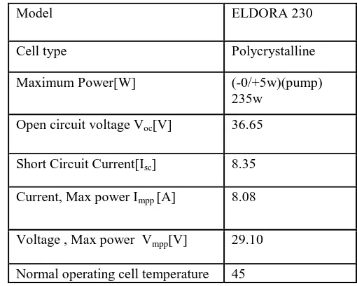
III. PHOTOVOLTAIC PANEL TO BE DEVELOPED In order to apply these concepts to developments of a solar cell model, the VIKRAM SOLAR PANEL PV- ELDORA 230 module has been chosen for modeling. This module has 50 series connected polycrystalline cells. The key specifications are shown in Table 1.
Table1. Key specifications of the VIKRAM SOLAR PV Panel
The performance of solar cell is normally evaluated under the standard test condition (STC), where an average solar spectrum at AM 1.5 is used, the irradiance is normalized to 1000W/m2, and the cell temperature is defined as 25 ºC.
IV. TYPES OF MODELS
The two models presented in this paper are part of a more complete study of models of cell or photovoltaic panels. The models that are analyzed and compared differ depending on if they are modeled with MATLAB/Simulink or with the support of some of their toolboxes. Below is a brief summary of each of the simulation forms analyzed in this work.
Model ELDORA 230
Cell type Polycrystalline
Maximum Power[W] (-0/+5w)(pump) 235w
Open circuit voltage Voc[V] 36.65
Short Circuit Current[Isc] 8.35
Current, Max power Impp [A] 8.08
Voltage , Max power Vmpp[V] 29.10
[image:2.612.50.282.183.347.2] [image:2.612.327.582.344.548.2]A. Matlab Programming
This model is made only in Matlab, based on mathematical equations that define the photovoltaic cell. From the work of Walker [7], Gonzalez [8] and Ahikiro [9] a function in Matlab [10] has been developed which calculates the current module from data of voltage, solar radiation and temperature. Setting the constant temperature or radiation, curves IV and PV will be obtained. From another script also calculates the maximum power point.
B. Matlab Tools
This section has taken into account two ways to represent the IV and PV curves. In the first form of representation, the graphic interface for curve fitting Cftool (Curve Fitting Toolbox) has been used. The International Journal on “Technical and Physical Problems of Engineering” (IJTPE), Iss. 10, Vol. 4, No. 1, Mar. 2012 47 starting point of this model is the manufacturer's datasheet, in which the IV and PV curves of the panel are represented. In this curve at least three coordinates (V, I) are known, (0, ISC), (Vmpp, Impp) and (VOC, 0). Manually more coordinates can be approximated to facilitate the representation. With these coordinates, the tool will provide an equation of a similar curve to the original one. In the second form, the model consists of two Matlab programs. The first serves for the presentation and data capture and calculations are made in the second one. These calculations are based on three functions of MATLAB: fsolve, fzero and lsqnonlin. In this case the data used were obtained experimentally from the panels analyzed. Data can be exchanged from one form of representation to another.
C. Basic Model in Simulink
This model is made based on [11,12]. It is a model like the one shown in section D, also based on mathematical Equation (1) but made with elements of Simulink. It is a basic model in which the values of Rs (0.001 Ω) and Rsh (1000 Ω) are assumed to be known.
D. Simulink Model with Tags
This is the usual way to model a PV cell that has been developed among other authors, by Villava [12]. It starts from the same equations as in section A, but it is developed in Simulink. Based on this kind of programming could also simulate the basic model of the previous section in this way. The model developed with tags, presented in this paper (Figures 4),
model in Section C is the basic model based on Equation (1). Therefore the results have to be the same. Fig. 4. Types of tags
Fig. 4
E. Model of Physical Component
This model is made from physical elements using Simscape. With those elements, electrical equivalent circuit diagram of the cell is performed.
F. Model of Advanced Component Library
This is the simplest model. It works with an element of SimElectronics, that is a toolbox dependent of Simscape. The element to model, Solar Cell, appears in the Source Library. Only, it is needed to enter the parameters that define the cell, provided by the manufacturer's data sheet.
G. Model According with Look Table Function
This model is created from experimental data of the panel that is going to be simulated. It is based on the element Look Table (2D). Lookup Tables library in Simulink which generates a vector of data, from the experimental data of irradiance, voltage and current. Then use the surface fitting tool.
V. MODEL BASED ON SIMULINK WITH TAGS
Figure 5.1. Simulink model with tags
From: Outputs the data type (or types) of the signal connected to the corresponding Goto block. Library: Signal Routing.
• Goto: Pass block input To/From blocks. Input can be of any type. Library: Signal Routing.
From/Goto combinations can be quite powerful in Simulink. These blocks are useful tools to structure a complex design which would otherwise have many crossing signal lines, a stylistic choice that can make a model harder to decipher. But,
From/Goto blocks can only be used with a local scope. They are basically nonfunctional, simply hiding a signal line from view. The model developed (Figure 5.1) is based on the equivalent circuit of solar cell (Fig.2.1) and its characteristic equation, Equation (1). Where current (I) obtained in the solar panel is defined by the following expression:
Figure 5.2 IV Curve results
The model developed is shown in Figure 5. In this model the irradiance (Ir) is a vector of value [200 400 600 800 1000]. It will be represented an IV characteristic curve for each irradiance value in the same graph, as shown in Figure 5.2. The same goes for the PV curve in Figure 5.3. If 50 cells are put in series a full panel simulation is obtained.
Figure 5.3 PV curves Result
VI. CONCLUSION
Since the field tests can be expensive and depend primarily on weather conditions it is very convenient to have simulation models to perform at any time. For this reason, in this paper, for the development of photovoltaic arrays the methods of modeling in MATLAB/SIMULINK have been analyzed. During analysis one of the method is selected and a model is developed on that. This model has been designed in Simulink with Tags. The blocks with tags makes the model more user-friendly. Such a
generalized PV model is easy to use for the implementation on Matlab/Simulink modeling and simulation platform.
Results presented in the paper clearly demonstrates, IV and PV characteristic curve similar to the graph that presents the manufacturer's data sheet of the solar panel. More similar the curve obtained, better the model will be.
ACKNOWLEDGMENT
The authors would like to acknowledge Dr. Fahim Ansari , Head of EEE department of BRCM college if Engineering and Technology for his valuable suggestions regarding Solar cell Model.
REFERENCES
[1] A. Zatirostami„Application of Photo Voltaic Systems in Production of Electricity‟, Australian Journal of Basic and Applied Sciences, 5(8): 655-658, 2011 ISSN 1991-8178.
[2] Dr.Mohamed Mokhtar Atteg , Eng. Marai Ali Khalifa, „ Photovoltaic Materials and Solar Cell Design‟, International Renewable Energy Congress November 5-7, 2010 – Sousse, Tunisia.
[3] A. Rostami, K. Abbasian, N. Gorji, „Efficiency Optimization in a Rainbow Quantum Dot Solar Cell‟, International Journal on Technical and Physical Problems of Engineering (IJTPE), Issue 7, Vol. 3, No. 2, pp. 106- 109, June 2011.
[4] M. Sojoudi, R. Madatov, T. Sojoudi, „Optimization of Efficiency of Solar Cells by Accelerated Electron ray to Have an Optimal and Constant Energy‟, International Journal on Technical and Physical Problems of Engineering (IJTPE), Issue 9, Vol. 3, No. 4, pp. 68-71, December 2011. [5] Kinal Kachhiya , Makarand Lokhande , Mukesh Patel ,
„MATLAB/Simulink Model of Solar PV Module and MPPT Algorithm‟, National conference on Recent trends in Engineering and technology, May 2011.
[6] S. Sheik Mohammed, „Modeling and Simulation of Photovoltaic module using MATLAB/Simulink‟, International Journal of Chemical and Environmental Engineering Volume 2, No.5, October 2011.
[7] G. Walker, “Evaluating MPPT Converter Topologies Using a Matlab PV Model”, Journal of Electrical and Electronics Engineering, Australia, Vol. 21, No. 1, pp. 49-56, 2001.
[8] F. Gonzaez-Longatt, “Model of Photovoltaic in MatlabTM”, 2nd Latin American Student Congress of Electrical Engineering and Computer Science (II CIBELEC 2005), Puerto la Cruz, Venezuela, April 2006. [9] A. Oi, “Design and Simulation of Photovoltaic Water Pumping System”,
Master Thesis, California Polytechnic State University, San Luis Obispo, CA, 2005.
[10] J.A. Ramos, I. Zamora, J.J. Campayo. „Modeling of Photovoltaic Module‟, International Conference on Renewable Energies and Power Quality (ICREPQ‟10) Granada, Spain, 23-25 March 2010.
[11] C. Osorio. Matlab-Simulink models, Mathworks. [12] http://ecee.colorado.edu/~ecen2060/matlab.
AUTHORS
First Author – Nisha Sharma –B.Tech(EEE), Persuing
M.Tech(Control and Instrumentation). , Email nisha.uptosky@gmail.com
Second Author – Dr. Fahim Ansari –Btech(EE),M.tech(EE) ,
Phd(Solar), Email fahim4002@yahoo.com
Third Author – Pawan Kr. Panday –Btech(EE), Mtech(Power