N A N O E X P R E S S
Open Access
Numerical study of a confined slot impinging jet
with nanofluids
Oronzio Manca
*†, Paolo Mesolella
†, Sergio Nardini
†, Daniele Ricci
†Abstract
Background:Heat transfer enhancement technology concerns with the aim of developing more efficient systems to satisfy the increasing demands of many applications in the fields of automotive, aerospace, electronic and process industry. A solution for obtaining efficient cooling systems is represented by the use of confined or unconfined impinging jets. Moreover, the possibility of increasing the thermal performances of the working fluids can be taken into account, and the introduction of nanoparticles in a base fluid can be considered.
Results:In this article, a numerical investigation on confined impinging slot jet working with a mixture of water and Al2O3nanoparticles is described. The flow is turbulent and a constant temperature is applied on the
impinging. A single-phase model approach has been adopted. Different geometric ratios, particle volume concentrations and Reynolds number have been considered to study the behavior of the system in terms of average and local Nusselt number, convective heat transfer coefficient and required pumping power profiles, temperature fields and stream function contours.
Conclusions:The dimensionless stream function contours show that the intensity and size of the vortex structures depend on the confining effects, given byH/W ratio, Reynolds number and particle concentrations. Furthermore, for increasing concentrations, nanofluids realize increasing fluid bulk temperature, as a result of the elevated thermal conductivity of mixtures. The local Nusselt number profiles show the highest values at the stagnation point, and the lowest at the end of the heated plate. The average Nusselt number increases for increasing particle concentrations and Reynolds numbers; moreover, the highest values are observed forH/W= 10, and a maximum increase of 18% is detected at a concentration equal to 6%. The required pumping power as well as Reynolds number increases and particle concentrations grow, which is almost 4.8 times greater than the values calculated in the case of base fluid.
List of symbols
Background
Heat transfer enhancement is very important in the industry, and several techniques are employed to realize this aim. Impinging jets, whether confined or uncon-fined, have been widely used for efficient cooling in industrial applications as a means of providing highly localized heat transfer coefficients, representing a possi-ble solution. Depending on the application, flow condi-tions can range from laminar to highly turbulent ones. Applications of impinging jets include drying of textiles, film and paper, cooling of gas turbine components and
the outer walls of combustors, freezing of tissue in cryo-surgery and manufacturing, material processing and electronic cooling. There are numerous articles dealing with this problem both numerically and experimentally as reported in the literature reviews on the subject [1-6]. Several studies have been developed on impinging air jets [1,2]. Recently, a greater attention has been dedi-cated to the impinging liquid jet since orders of magni-tude of the heat transfer rates are several times those of gas jets. Liquid jets have possible application to the cooling of heat engines [5,7], thermal control in electro-nic devices [8-10] and in the thermal treatment of metals and material processing [11-14].
In the application of jet impingements, circular or slot jets are the main jet configurations. For these two * Correspondence: [email protected]
†Contributed equally
Dipartimento di Ingegneria Aerospaziale e Meccanica, Seconda Università degli Studi di Napoli, Via Roma 29 - 81031 Aversa, Italy
configurations, flow and heat transfer mechanics are sig-nificantly different. It seems that greater research activ-ity on heat and mass transfer with circular impinging jets has been predominantly published [1-3,15,16]. How-ever, investigations on heat and mass transfer with slot jet impingement have attracted more attention recently. In fact, slot jet impingements offer many more beneficial features, such as higher cooling effectiveness, greater uniformity and more controllability, as underlined in [17]. For example, these factors allow for fulfillment of the increasing heat flux and decreasing dimensions in electronics packages [17-24]. The common types of impinging jets are with or without confinement. Con-fined impinging jets have the advantages of smaller space design, while unconfined impinging jets have an advantage of simple design and easy fabrication. The two types of impinging jets have their own merits, and they are both commonly used as the cooling solutions, and the literature reviews on the subject have been pro-vided in [2,3,6]. The effects of confinement on imping-ing jet heat transfer have been considered in [25-27]. Moreover, several studies show the importance of the subject and different cases have been investigated, such as confined slot-jet impingement on a moving plate [28], impinging jet on obliquely a flat surface [29], impinging jet on a porous medium [30] and slot jet impingement cooling on a semi-circular concave [31].
In order to obtain a heat transfer enhancement in jet impingement, different techniques have been employed, such as the insert of foams or fins [32]. These techni-ques determine a modification of the cooling system whereas the use of nanofluids in a coolant seems to be simpler in realizing a heat transfer enhancement [33]. However, nanofluids are to this day controversial in many areas such as inconsistencies in published data and disagreements on the heat transfer mechanisms, as observed by Gherasim et al. [34]. Various aspects of nanofluids have been covered in several reviews and some of these are given in [35-47].
The employment of nanofluids in impinging jets has been investigated recently by some researchers and, to the best of our knowledge, their investigations have been reported in [34,48-60]. The numerical investigation on hydrodynamic and thermal fields of Al2O3/water
nanofluid in a radial laminar flow cooling system carried out by Roy et al. [48] can be can be considered as the first article on an impinging jet. Those authors found that considerable heat transfer enhancement was observed up to 200% in the case of a nanofluid with 10% in nanoparticle volume concentration at a Reynolds number equal to 1200. However, a significant increase in wall shear stress was noticed increasing the nanopar-ticle volume concentration. The laminar-forced convec-tion flow of nanofluids between two coaxial and parallel
disks with central axial injection was investigated numerically considering temperature-dependent proper-ties by Palm et al. [51]. Results indicated a heat transfer benefit by adopting Al2O3/water nanofluid with a
volume fraction of nanoparticles of 4%. An increase of 25% was evaluated in terms of average wall heat transfer coefficient, when referred to the water. Moreover, the use of temperature-dependent properties determined for greater heat transfer predictions with corresponding decreases in wall shear stresses when compared to eva-luations employing constant properties. A numerical study on steady, laminar radial flow of a nanofluid in a simplified axi-symmetric configuration with axial cool-ant injection was performed by Roy et al. [52] for elec-tronic cooling applications. Also in this investigation increases in heat removal capabilities were detected with the use of nanofluids.
An experimental investigation in a confined and sub-merged impinging jet on a flat, horizontal and circular heated surface with nanofluid (Al2O3 dispersed in water)
was carried out by Nguyen et al. [56]. Experimental results were obtained for both laminar and turbulent flow regimes and they showed that, depending on the combination of nozzle-to-heated surface distance and particle volume fraction, the use of a nanofluid can determine a heat transfer enhancement in some cases, but an adverse effect on the convective heat transfer coefficient may occur in other cases. A circular confined and submerged jet impinging on a horizontal hot plate was numerically simulated by Vaziei and Abouali [57]. Water and 36-nm Al2O3-water nanofluid with various
particle volume fractions were considered as a working fluid for cooling the hot plate. Both laminar and turbu-lent impinging jets in various nozzle-to-plate distances and Reynolds numbers were simulated. The results showed that the use of Al2O3 nanoparticles in laminar
jets enhanced the heat transfer but for the turbulent jets Al2O3-water nanofluid had a lower performance for heat
removal compared with the base fluid. The heat transfer enhancement capabilities of Al2O3/water inside a
con-fined impinging jet cooling device was numerically stu-died by Gherasim et al. [34]. Results highlighted those limitations in the use of this nanofluid type in a radial flow configuration, due to the significant increase in the associated pumping power. Steady laminar incompressi-ble thermal alumina-water flow between parallel disks was simulated by Feng and Kleinstreuer [58]. The results indicated that the Nusselt number increases with higher nanoparticle volume fraction, smaller nanoparti-cle diameter, reduced disk-spacing and larger inlet Rey-nolds number. The laminar forced convective heat transfer features of Al2O3/water nanofluid in the
temperature-dependent properties [60]. Results showed the same trend given in the previous published works: the Nusselt number increases with the increases in Reynolds num-ber and nanoparticle volume fraction, though the increase in pressure drop is more significant with the increase of particle concentration. Furthermore, tem-perature-dependent thermo-physical properties of nano-fluids were found to have a marked bearing on the simulation results.
It seems that a slot-confined and submerged imping-ing jet on a flat surface with nanofluids has not been investigated in both laminar and turbulent flow regimes in spite of its importance in engineering applications such as electronic cooling and material processing.
In this article, a numerical investigation on turbulent flow on a slot-confined and submerged impinging jet on an isothermal flat surface is carried out. The results are given to evaluate the fluid dynamic and thermal features of the considered geometry with Al2O3/water
as the working nanofluid adopting the single phase model.
Methods
Geometrical model
A computational thermo-fluid dynamic analysis of a two-dimensional model, Figure 1a, which regards the impinging jet on a heated wall with nanofluids, is con-sidered in order to evaluate the thermal and fluid-dynamic performances, and study the velocity and temperature fields. The two-dimensional model has a length Lequal to 310 mm while the height H ranges from 24.8 to 124 mm and the jet orifice width W is 6.2 mm. A constant temperature value of 343 K is applied on the impingement bottom surface. Different values of H/W ratio, equal to 4, 6, 8, 10, 15 and 20, are considered. The working fluid is water or a mixture of water andg-Al2O3 nanoparticles with a
dia-meter of 38 nm, at different volume fractions equal to 1, 4 and 6%.
Physical properties of nanofluids
The working fluid is water or a mixture of water and
g-Al2O3 nanoparticles with a diameter of 38 nm, at
a)
[image:3.595.59.541.369.712.2]b)
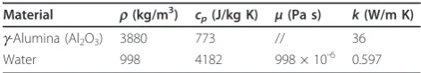
different volume fractions equal to 1, 4 and 6%. In Table 1, the values of density, specific heat, dynamic viscosity and thermal conductivity, given by Rohsenow et al. [61], are reported for water and g-Al2O3. The
presence of nanoparticles and their concentrations influence the mixture properties. A single-phase model was adopted, and the following equations were used for computing the thermal and physical properties of the considered nanofluids [62-65], given in Table 2. Density was evaluated using the classical formula developed for conventional solid-liquid mixtures, while the specific heat values were obtained by assuming the thermal equilibrium between particles and surrounding fluid [62,63].
Density: nf = −(1 ) bf +p (1)
Specific heat: cpnf = −(1 )cpbf +cpp (2)
Nanofluids may be considered as Newtonian fluids for low volume fractions, e.g., up to 10%, and for small tem-perature increases. In this way, for the viscosity as well as for thermal conductivity, formulas given by [64,65] were adopted:
Dynamic viscosity: nf =bf(1232+7 3. +1) (3)
Thermal conductivity: knf =kbf( .4 972+2 72. +1) (4)
However, it is well known that the evaluation of these properties by various research groups differs from each other because of the numerical and experimental approaches and processes adopted [64,65].
Mathematical description and governing equations
Steady-state, turbulent, incompressible, single-phase, and constant properties flow conditions are considered in the present analysis. The governing equations of conti-nuity, momentum and energy are solved in rectangular coordinates:
Continuity: ∂
∂xi
(
u)
= i 0 (5)
Mom.: ∂
∂ ( )= − ∂∂ + ∂∂ ∂ ∂ + ∂ ∂ − ∂ ∂ ⎛ ⎝ ⎜
x u u
P x x u x u x u x
j i j i j i j j i ij i j
2
3 ⎜⎜ ⎞ ⎠ ⎟⎟ ⎡ ⎣ ⎢ ⎢ ⎤ ⎦ ⎥ ⎥+ ∂∂ − ′ ′ ⎛ ⎝ ⎜ ⎞⎠⎟
xj u ui j
________ (6)
Energy: t
t e ∂ ∂ ⎡⎣ ( + )⎤⎦ = ∂ ∂ + ⎛ ⎝ ⎜ ⎞ ⎠ ⎟∂∂ +
x u E P x
c Pr T x u i i j p j i ij
( ) fff
⎡ ⎣ ⎢ ⎢ ⎤ ⎦ ⎥ ⎥ (7)
where E is the total energy, E=c Tp − P +u2 2 and (τij)eff is the deviatoric stress tensor, defined as
( )ij j
i i j i j ij u x u x u x
eff = eff eff
∂ ∂ + ∂∂ ⎛
⎝
⎜⎜ ⎞⎠⎟⎟ −23 ∂∂ (8)
The k-ε standard model with enhanced wall treat-mentis assumed. The transport equations are as follows [66]: ∂ ∂( )+ ∂∂ ( )= ∂ ∂ + ⎛ ⎝ ⎜ ⎞ ⎠ ⎟∂∂ ⎡ ⎣ ⎢ ⎢ ⎤ ⎦ ⎥ ⎥+( + )−
t k x ku x
k
x G G
i i j t k i
k b −YM+S (9)
∂ ∂( )+ ∂∂ ( )= ∂∂ + ⎛ ⎝ ⎜ ⎞ ⎠ ⎟∂∂ ⎡ ⎣ ⎢ ⎢ ⎤ ⎦ ⎥ ⎥+ +
t xi ui xj x C k G C
t i
1 k 3
G C
k S
b
( )− 2 +
2
(10)
whereGk is the production of turbulent kinetic energy
due to mean velocity gradients, Gbrepresents the
gen-eration of the turbulent kinetic energy due to buoyancy whileYM is referred to the fluctuation rates related to the overall dissipated turbulent thermal energy. In parti-cular,Gkmay be expressed by
G u u u
x
i j j i
k = − ′ ′ ∂ ∂
(11)
where C1ε and C2ε are constants; while the term
C v
u
3 =tanh defines the dependence rate of ε on
buoyancy; sk andserepresent the turbulent Prandtl numbers based on kandε, respectively; while SkandSε are further generation terms. The turbulent viscosity is defined by
t = C k2
(12)
whereCμis a constant. The model constant values are the following:
[image:4.595.55.291.689.730.2]C1ε = 1.44, C2ε = 1.92, Cμ = 0.09,sk = 1.0 andsε = 1.3.
Table 1 Material properties at a temperature of 293 K
Material r(kg/m3) c
p(J/kg K) μ(Pa s) k(W/m K)
g-Alumina (Al2O3) 3880 773 // 36
Water 998 4182 998 × 10-6 0.597
Table 2 Properties of nanofluids,single-phase model
r(kg/m3) cp(J/kg K) μ(Pa s) k(W/m K)
0% 998.2 4182 998 × 10-6 0.597
1% 1027 4148 1083 × 10-6 0.614
4% 1113 4046 1486 × 10-6 0.667
The enhanced wall treatmentapproach has been con-sidered. The assigned boundary conditions are
- Inlet jet section: uniform velocity and temperature profile;
- Outlet section: pressure outlet;
- Bottom wall: velocity components equal to zero and constant temperature;
- Upper wall: velocity components equal to zero and adiabatic condition.
The dimensionless parameters considered here are
Re=u WJ
(13)
Nu qW
T T
= −
(
)
H J f
(14)
= −
−
(
TT TT)
J
H J
(15)
where ujis the jet velocity, W is the jet width, q is the impingement surface heat flux,TH andTJ represent
the temperature of the impingement surface and the jet temperature, respectively.
Numerical procedure
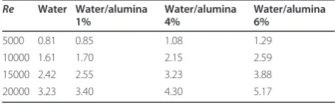
The governing equations of continuity, momentum and energy, reported in the previous section, are solved by the finite volume method by means of FLUENT code [67]. A steady-state solution and a segregated method are chosen to solve the governing equations, which are linearized implicitly with respect to dependent variables of the equation. A second-order upwind scheme is cho-sen for energy and momentum equations. The SIMPLE coupling is chosen as scheme to couple pressure and velocity. The convergence criteria of 10-5for the resi-duals of the velocity components and of 10-8 for the residuals of the energy are assumed. It is assumed that the incoming flow is turbulent at ambient temperature and pressure. Different inlet uniform velocities, corre-sponding to Reynolds numbers ranging from 5000 to
20000, were considered and they are reported in Table 3. Furthermore, the inlet turbulence intensity value is set to 2%.
Theenhanced wall treatment functions are activated to increase the model accuracy in the near-wall region. It is a two-layermethod with enhanced functions. The domain is divided into two regions, the near-wall region and the core ones, according to the turbulent Reynolds number, based on the distance-to-wall termy.
Rey = y k
[image:5.595.301.539.86.287.2] (16)
Table 3 Inlet velocities (m/s) Re Water Water/alumina
1%
Water/alumina 4%
Water/alumina 6%
5000 0.81 0.85 1.08 1.29
10000 1.61 1.70 2.15 2.59
15000 2.42 2.55 3.23 3.88
20000 3.23 3.40 4.30 5.17
[image:5.595.305.539.446.703.2]Figure 2Analysis of grid independence in terms of Nusselt number,H/W= 6,R= 5000 and= 0%.
[image:5.595.55.291.658.732.2]The core region, forRey> 200, is solved by means of the standard k-εmodel, while in the other region the Wolfstein model is applied [68].
Along the solid walls, no slip condition is employed, whereas a velocity inlet is given for the jet orifice and pressure conditions are set for the outlet sections.
Four different grid distributions are tested on the model with H/W ratio equal to 6 at Re = 5000, with water (= 0%) as working fluid, to ensure that the cal-culated results are grid independent. The four grids have 4950 (90 × 55), 19800 (180 × 110), 79200 (360 × 220), and 316800 (720 × 440) nodes, respectively. The grid mesh is structured in each case with grid adoption fory+ = 1 at adjacent wall region and a sketch is shown in Figure 1b. For the adiabatic wall and the bottom sur-face, nodes are distributed by means of an exponential relation (n= 0.9), to have a fine mesh near the impinge-ment region, where an equi-spatial distribution is
chosen. On the vertical ones, a bi-exponential (n= 0.8) distribution is considered.
Comparing the third- and fourth-mesh configurations, in terms of average and stagnation point Nusselt num-ber, results are very close, and the relative errors are very little, as reported in Figure 2. As a result, the third grid case has been adopted because it ensured a good compatibility between the machine computational time and the accuracy requirements.
Results are validated by comparing the obtained numerical data with the experimental and numerical ones, given in [28,69,70]. Figure 3 presents the compari-son in terms of average Nusselt number profiles, for the cases, characterized by Re= 11000,H/W= 6,TJ = 373
K and TH = 338 K. It is observed that the numerical
results, obtained in this work, fit very well with the experimental ones given in [5,6] both near the stagna-tion point region and at the side one.
a)
b)
c)
[image:6.595.57.542.88.455.2]d)
a)
b)
c)
[image:7.595.56.541.90.453.2]d)
Figure 5Temperature fields.(a)H/W= 10,Re= 10000 and= 0%; (b)H/W= 10,Re= 10000 and= 4%;(c)H/W= 4,Re= 10000 and= 4%;(d)H/W= 10,Re= 20000 and= 4%.
[image:7.595.59.539.484.711.2]Results and discussion
A computational thermo-fluid dynamic analysis of a two-dimensional model, regarding a confined impinging jet on a heated wall with nanofluids, is considered to evaluate the thermal and fluid-dynamic performances and study the velocity and temperature fields. Different inlet velocities are considered to ensure a turbulent regime, and the working fluids are water and mixtures of water andg-Al2O3 at different volume fractions,
trea-ted by a single-phase model approach. The range of Reynolds numbers, geometric ratio and volume fractions are given below:
• Reynolds number, Re: 5000, 10000, 15000 and 20000;
•H/Wratio: 4, 6, 8, 10, 15 and 20;
•particle concentrations, : 0, 1, 4 and 6%.
Results are presented in terms of average and local Nusselt number profiles, as a function of Reynolds num-ber, H/Wratio and particle concentrations; moreover, dimensionless temperature fields and stream function contours are provided.
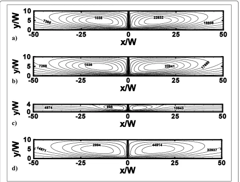
Figures 4 and 5 depict the stream lines contours and the temperature fields, respectively, for the representative
Figure 7Profiles ofqw/q0wratio alongx/W:(a)H/W= 4,= 0%,Re= 5000, 10000, 15000 and 20000;(b)H/W= 4,Re= 5000,= 0, 1, 4 and
cases withH/W= 4 and 10, atRe= 10000 and 20000 and = 0 and 4%. According to Figure 4, two counter-rotating vortex structures are generated as the jet impinges on the bottom surface and only one stagnation point, where velo-city and temperature gradients are very high, is observed. This is due to the jet entrainment and confining effects of the upper adiabatic surfaces. Vortex intensity and size depend onH/Wratio, factors such as the confining effects, Reynolds number, and particle concentrations. It can be seen in Figure 4a, b, atRe= 10000,H/W= 10 and= 0 and 4%, the introduction of particles leads to a little smoother eddies with a low intensity increase, because the nanofluid viscosity is higher than water. AsH/Wratio decreases from 10 to 4, atRe= 10000 and= 4%, vortices are less strong and smaller as they extinguish atx/W
values equal to about -30 and 30, as pointed out in Figure 4b, c. AsReincreases, the separation area near the inlet section becomes larger while the fluid stream results to be more compressed towards the impingement surface, as observed in Figure 4d.
The temperature fields, depicted in Figure 5, follow the stream line patterns. For increasing concentrations, nanoparticles produce an increase of fluid bulk tempera-ture, because of the elevated thermal conductivity of mixtures. Near the impingement surface, temperature grows and tends to decrease for increasingx/Wvalues. For larger Reynolds numbers, the efficiency of heat transfer increases.
[image:9.595.59.540.283.708.2]The variation of local Nusselt number along the impingement plate for Re = 20000, H/W = 4 and=
6% and for Re= 5000,H/W = 6 and different concen-trations, is shown in Figure 6a, b, respectively. It is observed that the highest values ofNux are evaluated at the stagnation point for all the considered cases; their values are 214 and 239 for H/W = 4 and H/W = 10, respectively. For lowH/Wvalues, local Nusselt number decreases more quickly than high H/W ratios. At the end of the plate, for any considered H/W,Nux reaches similar values equal to about 25, as observed in Figure 6a. In Figure 6b, it is shown how the variation of nano-fluid concentration affects the heat transfer. Higher heat transfer enhancements are observed for= 4, 6%, espe-cially, near the impingement location. This does not happen only for H/W = 4 as can be understood from the average Nusselt number value trends, reported later, in comparison with otherH/Wratios.
In Figure 7, the variation of localqw/q0wratio is shown. Theqw/q0wvalue represents the local ratio between the local total heat flux and total heat flux at stagnation point
a)
b)
[image:10.595.59.540.88.504.2]c)
d)
Figure 9Average convective heat transfer coefficient profiles as function ofRe,= 0, 1, 4 and 6%:(a)H/W= 4;(b)H/W= 6;(c)H/W= 8;(d)H/W= 10.
[image:10.595.305.537.539.746.2]for any case. The maximum value is reached at the stagna-tion point of any considered case. AsReincreases,qw/q0w ratio increases. Difference in terms ofqw/q0wis more sig-nificant passing fromRe= 5000 to 10000 than the other consideredRe. In fact, atx/W= 4, there is a difference of 0.12 in terms ofqw/q0wwhile in the other cases, the largest difference is 0.9. The heat transfer augmentation is more significant near the stagnation point than in correspon-dence with the end of the impinged plate. In Figure 7b, it is observed as the nanofluid concentration has very little influence onqw/q0w. The effects ofH/Ware underlined in Figure 7c: near the stagnation point,qw/q0w ratio has almost the same value for allH/W. Fromx/W= 4 curves
spread out andqw/q0wincreases asH/Wincreases. This affects the results in terms of average Nusselt number, cal-culated at differentH/Wratios.
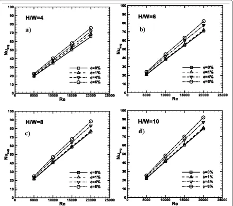
The average Nusselt number profiles as function of
Re are depicted in Figure 8 forH/W = 4, 6, 8, and 10. Profiles increase as Reincreases for all the considered cases. It is observed that asincreasesNuavgbecomes
higher for a fixed value of Re. Passing from = 0% to = 1%, a significant increase ofNuavg, only forH/W=
[image:11.595.58.541.267.700.2]4 configuration is noted, where it passes from 35 to 37 at Re = 15000 or 65 to 69 for Re = 20000. For the other cases, a significant heat transfer enhancement is found for the highest values; in fact in these cases,
passing from = 0% to = 1%, the maximum enhancement is found to be equal to 1.22 times forH/ W= 10 at Re= 20000.
The heat transfer enhancement is evident, also obser-ving the average heat transfer coefficient profiles, described in Figure 9. Results are given for different Re,
H/Wratios and concentrations. The maximum values of
havg are calculated for the highest values of Re, H/W
and concentrations considered. In fact, for H/W= 10 and Re = 20000, it results that havg is equal to about
7600, 8000, 9400 and 10500 W/m2K, as depicted in
Figure 9d, while, atH/W = 4 andRe = 20000,havg are
equal to about 6200, 6800, 7700, and 8600 W/m2K, for = 0, 1, 4, and 6%, respectively.
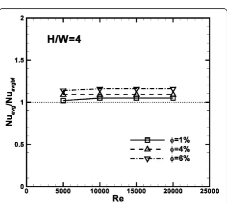
Figure 10 shows the average Nusselt number profiles, referred to the values calculated for the base fluid, as a function of Reynolds number for particle concentrations equal to 1, 4 and 6% atH/Wratio of 4. It is observed that the ratioNuavg/Nuavg, bfis greater than one for all the
[image:12.595.63.539.89.300.2]configurations analyzed and rises slightly for increasing Reynolds numbers and concentrations; in fact, the high-est value of 1.18 is detected atRe= 20000 and= 6%.
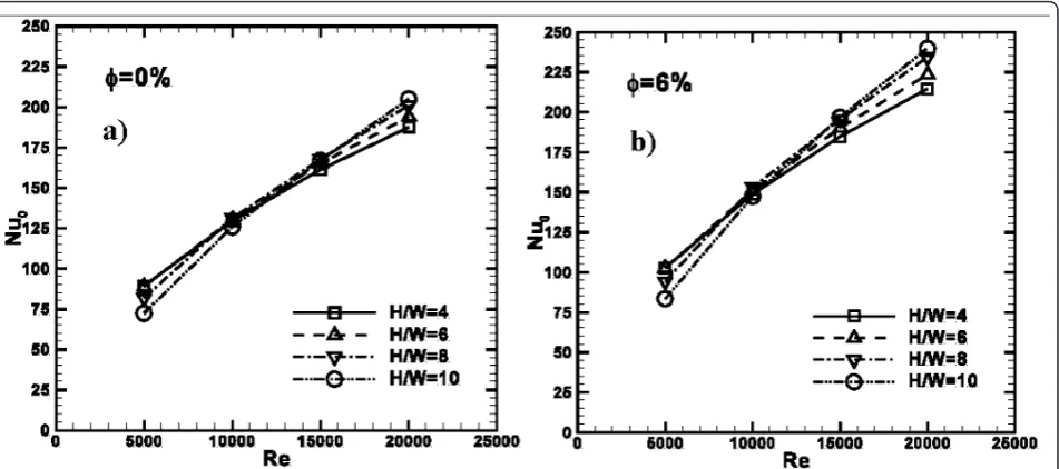
Figure 13Average Nusselt number profiles as a function ofRefor differentH/Wratios:(a)= 0%;(b)= 6%.
[image:12.595.59.537.505.712.2]The results in terms of local Nusselt numbers, calcu-lated for the stagnation point, are depicted in Figure 11. They are provided as a function of Reynolds num-bers and given for different concentrations for different
H/W ratios, equal to 4, 6, 8, and 10. It is shown that profiles increase almost linearly with increasing Rey-nolds numbers for all the considered concentrations and H/W ratios. Moreover, the Nu0 values are the highest for = 6% for all the considered Reynolds numbers. For example, comparing the results for = 1, 4, and 6%, with the base fluid ones, an increase in values of 2.7, 10.8, and 16.2% are detected for H/W= 4 at Re = 20000, respectively. Moreover, Nu0 values
[image:13.595.57.291.88.298.2]rises as H/Wincreases forRe > 10000, as observed in Figure 11b, c, d.
In fact, Figure 12 shows thatNu0is maximum in
corre-spondence withH/W= 4 forRe< 10000 andH/W= 10 for higher Reynolds numbers for all the concentrations. For= 0%, atRe= 5000Nu0values are about 70, 81, 86,
[image:13.595.59.541.308.754.2]and 87, while atRe= 20000,Nu0= 195, 197, 200, and
Figure 14Average Nusselt number profiles as a function ofH/
WforRe= 5000 and 20000,= 0 and 6%.
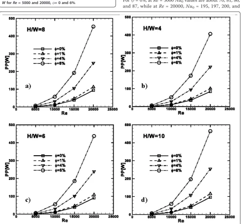
Figure 15Profiles of the required pumping power as a function ofRe, for= 0, 1, 4 and 6%:(a)H/W= 4;(b)H/W= 6;(c)H/W= 8;(d)
205, forH/W= 4, 6, 8, and 10, respectively. The results for= 6% are depicted in Figure 12b; it is shown that at
Re= 5000 the maximum value of the stagnation point Nusselt number is about 102, 100, 93, and 82, forH/W= 4, 6, 8, and 10, respectively. For the same geometrical configurations, at Re= 20000,Nu0 values are equal to
215, 225, 235, and 240.
Results in terms of average Nusselt numbers are shown in Figure 13, for differentH/Wratios and = 0, 6%. The profiles increase linearly asReincreases as well as H/W ratio. In fact, the highest values of Nuavg are
detected forH/W = 10 while the minimum ones forH/ W= 4. Moreover, average Nusselt numbers increase as increases; thus, Nuavg values are equal to 42 and 79
[image:14.595.302.535.262.728.2]for water, as depicted in Figure 13a, while for= 6%, they are equal to 48 and 92, as pointed out by Figure 12b, atRe= 10000 and 20000, respectively.
Figure 14 confirms that the configurations withH/W
= 10 exhibit the maximum values of the average Nusselt numbers for all the considered Reynolds numbers and concentrations. In fact, atRe= 5000 and 20000, the pro-files increase as H/W rises until H/W = 10, and then they decrease forH/W= 15 and 20.
The pumping power is defined as PP =VΔP, and its profiles are shown in Figure 15, for all the considered
H/W values, concentrations and as a function of Reynolds number. The required power has a square dependence on Re. It increases as H/W and particle concentration increase. For example, as observed in Fig-ure 15a, atH/W = 4, for water PP = 15 and 90 W atRe
= 10000 and 20000, respectively, while for= 6% PP = 50 and 410 W. At the same Re, for H/W = 10, PP is equal to 18 W, as underlined in Figure 15d, and 98 W for water, and 58 and 470 W for= 6%, respectively.
The pumping power ratio, referred to the base fluid values, is described in Figure 16. It is observed that the ratio does not seem to be dependent onRe, and PP/PPbfratio
increases as concentration increases, as expected. In fact, at
Re= 15000, the required pumping power is 1.2, 2.6 and 4.8 times greater than the values calculated in case of water.
Conclusions
A numerical analysis of a two-dimensional model on a confined impinging jet with nanofluids has been carried out to evaluate the thermal and fluid-dynamic perfor-mances and study the velocity and temperature fields.
Table 4 List of symbols
Symbol Quantity SI Unit
cp Specific heat J/kg K
H Channel height m
h Heat transfer coefficient W/m2K
k Turbulent kinetic energy J
L Channel length m
Nu Nusselt number Equation 11
P Pressure Pa
PP Required pumping power W
Pr =ν/a Prandtl number
q Impingement surface heat flux W/m2
Re Reynolds number Equation 10
T Temperature K
u Velocity component m/s
V Volume flow rate m3/s
W Jet width m
x,y Spatial coordinates m
Greek symbols
δ Kronecher delta function
ε Rate of dissipated turbulent thermal energy
Nanoparticle concentration
l Thermal conductivity W/mK
μ Dynamic viscosity Pa s
r Density kg/m3
s Turbulent Prandtl number
τ Wall shear stress kg/m
ν Kinematic viscosity m2/s
Subscripts
0 Stagnation point
a Ambient
avg Average
bf Base fluid
f Fluid
H Heated
J Jet
nf Nanofluid
p Particle
t Turbulent
[image:14.595.57.289.503.703.2]The bottom impinged wall is heated at a constant tem-perature and different fluid velocities are considered in the range 5000-20000. The base fluid is water and dif-ferent volume concentrations of Al2O3nanoparticles are
taken into account by adopting a single-phase model approach. Furthermore, differentH/Wratios have been studied. The dimensionless stream function contours showed that the vortex intensity and size depend onH/ W ratio, such as on the confining effects, Reynolds number and particle concentrations. Furthermore, for increasing concentrations, nanofluids produce an increase of fluid bulk temperature, because of the ele-vated thermal conductivity of mixtures. The local Nus-selt number profiles present the highest values at the stagnation point and the lowest at the end of the heated plate. The highest values of the average Nusselt num-bers increase as the particle concentrations and Rey-nolds numbers increase and the highest values are observed forH/W= 10. A maximum increase of 18% is detected at = 6%. The required pumping power increases as well as Reynolds number, and particle con-centrations grow, which is almost 4.8 times greater than the values calculated in the case of water. For list of symbols please see Table 4.
Acknowledgements
This study was supported by SUN Grant Initiative of 2008 grant and by MIUR with Articolo D.M. 593/2000 Grandi Laboratori“EliosLab”.
Authors’contributions
All the authors have made substantial contributions in order to write this work. PM and DR developed the numerical model, ran the simulation and acquired data. The analysis and the interpretation of data have been carried out together with OM and SN. All the authors have been involved in drafting the manuscript and revising it critically and OM and SN have given final approval of the version to be published.
Competing interests
The authors declare that they have no competing interests.
Received: 14 December 2010 Accepted: 1 March 2011 Published: 1 March 2011
References
1. Martin H:Heat and mass transfer between impinging gas jets and solid surface.Adv Heat Transfer1977,13:1-60.
2. Downs SJ, James EH:Jet impingement heat transfer-a literature survey. Tech. Rep. 1987-HT-35, ASME.
3. Jambunathan K, Lai E, Moss M, Button B:A review of heat transfer data for single circular jet impingement.Int J Heat Fluid Flow1992,13:106-115. 4. Viskanta R:Heat transfer to impinging isothermal gas and flame jets.Exp
Thermal Fluid Sci1993,6:111-134.
5. Webb B, Ma CF:Single-phase liquid jet impingement heat transfer.Adv Heat Transfer1995,26:105-117.
6. Tesar V, Travnicek Z:Increasing heat and/or mass transfer rates in impinging jets.J Vis2005,8:91-98.
7. Ma CF, Bergles AE:Convective heat transfer on a small vertical heated surface in an impingement circular liquid jet.InHeat Transfer Science and Technology.Edited by: Wang BX. New York: Hemisphere; 1990:193-200. 8. Ma CF:Fundamental research on extremely small size liquid jet
impingement heat transfer.Proceedings of the 3rd International Thermal Energy Congress: 28 June-1 August 1997; Kitakyushu, Japan1997, 195-202.
9. Jiji LM, Dagan Z:Experiment investigation of single phase multi-jet impingement cooling of an array of microelectronic heat sources.In Cooling Technology for Electronic Equipment.Edited by: Aung W. New York: Hemisphere; 1988:332-352.
10. Punch J, Walsh E, Grimes R, Jeffers N, Kearney D:Jets and rotary flows for single-phase liquid cooling: an overview of some recent
experimental findings.Proceedings of the 11th International Conference on Thermal, Mechanical and Multi-Physics Simulation, and Experiments in Microelectronics and Microsystems, EuroSimE 2010: 26-28 April 2010; Bordeaux2010, 5464505.
11. Kohing FC:Waterwall: water cooling system.Iron-Steel Eng1985,62:30-36. 12. Ma CF, Yu J, Lei DH, Gan YP, Tsou FK, Auracher H:Transient jet
impingement boiling heat transfer on hot surfaces.InMultiphase Flow and Heat Transfer-Second International Symposium.Edited by: Chen XJ et al. New York: Hemisphere; 1990:349-357.
13. Viskanta R:Heat transfer in material processing.InHandbook of Heat Transfer..3 edition. Edited by: Rohsenow WM, Hartnett JP, Cho YI. New York: McGraw-Hill; 1998:.
14. Schuettenberg S, Krause F, Hunkel M, Zoch HW, Fritsching U:Quenching with fluid jets.Mater Werkst2010,40:408-413.
15. Liu Z, Lienhard VJH, Lombara JS:Convective heat transfer by impingement of circular liquid jets.J Heat Transfer1991,113:571-582. 16. Ma CF, Zhao YH, Masuoka T, Gomi T:Analytical study on impingement
heat transfer with single-phase free-surface circular liquid jets.J Thermal Sci1996,5:271-277.
17. Chen YC, Ma CF, Qin M, Li YX:Theoretical study on impingement heat transfer with single-phase free-surface slot jets.Int J Heat Mass Transfer 2005,48:3381-3386.
18. Zhuang Y, Ma CF, Qin M:Experimental study on local heat transfer with liquid impingement flow in two-dimensional micro-channels.Int J Heat Mass Transfer1997,40:4055-4059.
19. Lin ZH, Chou YJ, Hung YH:Heat transfer behaviors of a confined slot jet impingement.Int J Heat Mass Transfer1997,40:1095-1107.
20. Chiriac VA, Ortega A:A numerical study of the unsteady flow and heat transfer in a transitional confined slot jet impinging on an isothermal surface.Int J Heat Mass Transfer2002,45:1237-1248.
21. Park TH, Choi HG, Yoo JY, Kim SJ:Streamline upwind numerical simulation of two-dimensional confined impinging slot jets.Int J Heat Mass Transfer2003,46:251-262.
22. Sahoo D, Sharif MAR:Numerical modeling of slot-jet impingement cooling of a constant heat flux surface confined by a parallel wall.Int J Thermal Sci2004,43:877-887.
23. Lee HG, Yoon HS, Ha MY:A numerical investigation on the fluid flow and heat transfer in the confined impinging slot jet in the low Reynolds number region for different channel heights.Int J Heat Mass Transfer 2008,51:4055-4059.
24. Sivasamy A, Selladurai V, Kanna PR:Jet impingement cooling of a constant heat flux horizontal surface in a confined porous medium: mixed convection regime.Int J Heat Mass Transfer2010,53:5847-5855. 25. Lytle D, Webb B:Air jet impingement heat transfer at low nozzle-plate
spacings.Int J Heat Mass Transfer1994,37:1687-1697.
26. Behnia M, Parneix S, Shabany Y, Durbin PA:Numerical study of turbulent heat transfer in confined and unconfined impinging jets.Int J Heat Mass Transfer1999,20:1-9.
27. Choo KS, Kim SJ:Comparison of thermal characteristics of confined and unconfined impinging jets.Int J Heat Mass Transfer2010,53:3366-3371. 28. Sharif MAR, Banerjee A:Numerical analysis of heat transfer due to
confined slot-jet impingement on a moving plate.Appl Thermal Eng 2009,29:532-540.
29. Ibuki K, Umeda T, Fujimoto H, Takuda H:Heat transfer characteristics of a planar water jet impinging normally or obliquely on a flat surface at relatively low Reynolds numbers.Exp Thermal Fluid Sci2009,33:1226-1234. 30. Dórea FT, de Lemos MJS:Simulation of laminar impinging jet on a
porous medium with a thermal non-equilibrium model.Int J Heat Mass Transfer2010,53:5089-5101.
31. Yang YT, Wei TC, Wang YH:Numerical study of turbulent slot jet impingement cooling on a semi-circular concave.Int J Heat Mass Transfer 2011,54:482-489.
33. Choi SUS:Enhancing thermal conductivity of fluids with nanoparticles, developments and applications of non-Newtonian flows.ASME FED1995,
231:99-105.
34. Gherasim I, Roy G, Nguyen CT, Vo-Ngoc D:Heat transfer enhancement and pumping power in confined radial flows using nanoparticle suspensions (nanofluids).Int J Thermal Sci2011,50:369-377. 35. Das SK, Choi SUS, Patel HE:Heat transfer in nanofluids-a review.Heat
Transfer Eng2006,27:3-19.
36. Buongiorno J:Convective transport in nanofluids.J Heat Transfer2006,
128:240-250.
37. Daungthongsuk W, Wongwises S:A critical review of convective heat transfer of nanofluids.Renew Sustain Energy Rev2007,11:797-817. 38. Trisaksri V, Wongwises S:Critical review of heat transfer characteristics of
nanofluids.Renew Sustain Energy Rev2007,11:512-523.
39. Yu W, France DM, Routbort JL, Choi SUS:Review and comparison of nanofluid thermal conductivity and heat Transfer enhancements.Heat Transfer Eng2008,29:432-460.
40. Keblinski P, Prasher R, Eapen J:Thermal conductance of nanofluids: is the controversy over?J Nanoparticle Res2008,10:1089-1097.
41. Kakaç S, Pramuanjaroenkij A:Review of convective heat transfer enhancement with nanofluids.Int J Heat Mass Transfer2009,52:3187-3196. 42. Choi SUS:Nanofluids: from vision to reality through research.J Heat
Transfer2009,131:1-9.
43. Buongiorno J,et al:A benchmark study on the thermal conductivity of nanofluids.J Appl Phys2009,106:1-9.
44. Özerinç S, Kakaç S, Yazıcıoğlu AG:Enhanced thermal conductivity of nanofluids: a state-of-the-art review.Microfluid Nanofluid2010,8:145-170. 45. Wang L, Fan J:Nanofluids research: key issues.Nanoscale Res Lett2010,
5:1241-1252.
46. Godson L, Raja B, Lal DM, Wongwises S:Enhancement of heat transfer using nanofluids-an overview.Renew Sustain Energy Rev2010,14:629-641. 47. Venerus D,et al:Viscosity measurements on colloidal dispersions
(nanofluids) for heat transfer applications.Appl Rheol2010,20:445-462. 48. Roy G, Nguyen CT, Lajoie P:Numerical investigation of laminar flow and
heat transfer in a radial flow cooling system with the use of nanofluids. Superlattices Microstruct2004,35:497-511.
49. Maiga S, Palm SJ, Nguyen CT, Roy G, Galanis N:Heat transfer
enhancement by using nanofluids in forced convection flows.Int J Heat Fluid Flow2005,26:530-546.
50. Roy G, Palm SJ, Nguyen CT:Heat transfer and fluid flow of nanofluids in laminar radial flow cooling systems.J Thermal Sci2005,14:362-367. 51. Palm SJ, Roy G, Nguyen CT:Heat transfer enhancement with the use of
nanofluids in radial flow cooling systems considering temperature-dependent properties.Appl Thermal Eng2006,26:2209-2218. 52. Roy G, Nguyen CT, Comeau M:Numerical investigation of electronic
component cooling enhancement using nanofluids in a radial flow cooling system.J Enhanc Heat Transfer2006,13:101-115.
53. Schoeppler M:Correspondence address diverging ink-jet technologies and applications.Proceedings of the International Conference on Digital Printing Technologies: 16-17 September 2006; Denver2006, 1-2. 54. Liu ZH, Qiu YH:Boiling heat transfer characteristics of nanofluids jet
impingement on a plate surface.Heat Mass Transfer2007,43:699-706. 55. Liu ZH, Qiu YH:The boiling heat transfer of water based nanofluid jet
impingement on a plate surface.J Shanghai Jiaotong Univ2007,
41:1658-1661.
56. Nguyen CT, Galanis N, Polidori G, Fohanno S, Popa CV, Le Bechec A:An experimental study of a confined and submerged impinging jet heat transfer using Al2O3-water nanofluid.Int J Thermal Sci2009,48:401-411. 57. Vaziei P, Abouali O:Numerical study of fluid flow and heat transfer for Al2O3-water nanofluid impinging jet.Proceedings of the 7th International Conference on Nanochannels, Microchannels and Minichannels 2009: 22-24 June 2009; Pohang2009, 977-984.
58. Feng Y, Kleinstreuer C:Nanofluid convective heat transfer in a parallel-disk system.Int J Heat Mass Transfer2010,53:4619-4628.
59. Yang YT, Lai FH:Numerical study of heat transfer enhancement with the use of nanofluids in radial flow cooling system.Int J Heat Mass Transfer 2010,53:5895-5904.
60. Yang YT, Lai FH:Numerical investigation of cooling performance with the use of Al2O3/water nanofluids in a radial flow system.Int J Thermal Sci 2011,50:61-72.
61. Rohsenow WM, Hartnett JP, Cho YI:Handbook of Heat Transfer.3 edition. New York: McGraw-Hill; 1998.
62. Pak BC, Cho YI:Hydrodynamic and heat transfer study of dispersed fluids with submicron metallic oxide particles.Exp Heat Transfer1998,
11:151-170.
63. Maiga SEB, Nguyen CT, Galanis N, Roy G:Heat transfer behaviours of nanofluids in a uniformly heated tube.Superlattices Microstruct2004,
35:543-557.
64. Maiga SEB, Cong Tam N, Galanis N, Roy G, Mare T, Coqueux M:Heat transfer enhancement in turbulent tube flow using Al2O3nanoparticle
suspension.Int J Numer Methods Heat Fluid Flow2006,16:275-292. 65. Palm SJ, Roy G, Nguyen CT:Heat transfer enhancement with the use of
nanofluids in radial flow cooling systems considering temperature dependent properties.Appl Thermal Eng2006,26:2209-2218.
66. Launder BE, Spalding DB:The numerical computation of turbulent flows. Comput Methods Appl Mech Eng1974,3:269-289.
67. FLUENT Computational Fluid Dynamic Code Version 6.3 User Guide, Fluent, Inc:[http://www.fluent.com].
68. Wolfstein M:The velocity and temperature distribution of one-dimensional flow with turbulence augmentation and pressure gradient. Int J Heat Mass Transfer1969,12:301-318.
69. Cadek FFA:Fundamental investigation of jet Impingement heat transfer. Ph.D ThesisUniversity of Cincinnati; 1968.
70. Gordon R, Akfirat JC:Heat transfer characteristics of impinging two-dimensional air jets.J Heat Transfer1966,88:101-108.
doi:10.1186/1556-276X-6-188
Cite this article as:Mancaet al.:Numerical study of a confined slot impinging jet with nanofluids.Nanoscale Research Letters20116:188.
Submit your manuscript to a
journal and benefi t from:
7 Convenient online submission 7 Rigorous peer review
7 Immediate publication on acceptance 7 Open access: articles freely available online 7 High visibility within the fi eld
7 Retaining the copyright to your article