http://dx.doi.org/10.4236/jsea.2014.79070
How to cite this paper: Lavrischeva, E., Stenyashin, A. and Kolesnyk, A. (2014) Object-Component Development of Applica-tion and Systems Theory and Practice. Journal of Software Engineering and Applications, 7, 756-769.
http://dx.doi.org/10.4236/jsea.2014.79070
Object-Component Development of
Application and Systems Theory and
Practice
Ekaterina Lavrischeva, Andrey Stenyashin, Andrii Kolesnyk
Institute of Software Systems of NAS, Kiev, Ukraine
Email: [email protected], [email protected], [email protected]
Received 9 June 2014; revised 4 July 2014; accepted 30 July 2014
Copyright © 2014 by authors and Scientific Research Publishing Inc.
This work is licensed under the Creative Commons Attribution International License (CC BY).
http://creativecommons.org/licenses/by/4.0/
Abstract
The Оbject-Componet Development (ОCD) is a variety of the compositional programmings, where a role of elements of assembling is warmed by objects, interfaces and components. For developing application systems, the theory of design of subject domain based on Frege object theory is deve l-oped, together with the presentation of their functions by methods and interfaces with formal a n-notations for saving them in libraries. Mathematical vehicle ОCDs are models, methods, algebra of operations of objective analysis and their configuring with the use of the component algebra of running, evolution and transformation of data types that are passed between objects through i n-terfaces. Row of the theoretical and applied aspects ОCD was realized in the instrumental-tech- nological complex (ІТC) as CASE-instruments of web-site http://sestudy.edu-ua.net. With their help the students can study, create, model, certify and accumulate or configure the objects and components into repository of ITC, and also assemble together from them in more complex a p-plied systems.
Keywords
Object, Reuses, Theory, Object Model, Component, Interface, Applied Systems, Exchanging, Interoperability, Operations, Evolution Systems
1.
Introduction
At the turn of 1980s Grady Booch suggested object-oriented approach that changed the way of software devel-opment process. At that point of time structured programming approach had reached the crisis of complexity. As
*
such, appearance of object-oriented programming (OOP) approach by Grady Booch was seen as a way out of the crisis of the application complexity. Many analysts and programmers were looking into this approach with skepticism by seeing it as fashion and not as competitive advantage. The main thing that OOP gives is reducing the complexity of software artifacts, the ability to add and remove objects without any difficulty, hereby solving some aspects of the crisis of complexity.
Since the Institute of Software Systems was formed, the department of the Software Engineering began stud-ying OOP approach for domain modeling and developing applied systems (AS). Applications based on objects are more robust and maintainable by easy adding or removing certain objects [1]-[3].
The theory and technology of producing compound systems from reusable software resources were developed over many years [1]-[7]. In a single conceptual framework, this technology combines theoretical object simula-tion and object model (OM) with object-funcsimula-tions and interfaces. At the same time, a large number of software reusable resources have been accumulated along with the development of component approach in terms of the components composition, yielding in object-component theory. This new development approach allows con-structing compound applications by using various kinds of systems, functional components and services. Some aspects of the theory focused on the interoperability of software resources and configuring these resources in software applications and AS.
This paper provides the basics of the improved theory of OOP analysis of the subject domain, modeling the objects in the domain with software components using component theory of isomorphic object transformation, adaptation and configuration into compound structure of the software application.
2.
Mathematical Modeling of Object Model of Domains
The object-component theory was built on base of OOP formalisms, Frege triangle and Von Neumann-Ber- nays-Gödel set theory. This gives a chance to create common mechanism to generalize the notion of object with the appropriate properties and characteristics. The object is defined on the object level analysis involving logical and mathematical concepts of representation, object function specification, Object Model (OM) [2] [3]-[7].
An object is considered as a set О = (О0, О1..., Оn), where О0 is the base object of domain. An object of
do-main O denotes a named part of the real world with a certain level of abstraction; it is described by Free triangle (Denotation, Sign, Concept) (Figure 1).
On this figure, each object O is presented as Oil= Oil(Nay, Deny,and Coin), where Nay, Deny, and Coin are a sign (name), denotation and the concept of object, respectively:
• The sign sets a name of a certain essence in the real world; • The denotation designates an essence by sign;
• The concept reflects semantics of the denotation, which is specified at levels of design of objects, bringing in the mathematical apparatus.
2.1. Levels of Logical and Mathematical Modeling of Domain
Design of domain model is performed at the four logical and mathematical levels of object definition (Figure 2): 1) Generalized level is used to determine the basic concepts of the given domain excluding their properties; 2) Structural level is used to determine the location of objects in the structure of the model and establish rela-tionships between these objects;
3) Characteristic level serves for setting the general concepts and specific features of objects;
4) Behavioral level determines the behavior and modification of objects based on events that they create in their interaction with each other.
Axiom 1. Domain area that is modeled from objects is an object itself. Axiom 2. Domain area that is modeled may be a part of another domain area.
When modeling an object from any given domain area, it has at least one property or characteristic, semantics and unique identification in a set of objects of that domain area and the set of properties (predicates) providing relationships between objects in the given domain area.
The property of the object is defined by a unary predicate that takes value of true for its external and internal features of the model.
I
III
II
Sign, WordDenotation,
Subject (reality) Concept, Idea
Designate
Express
Determine
Figure 1. Gottlob Frege triangle.
O0 O1 ... On
I. Generalized Level
Defines a set of objects
O1 O2 On
II. Structural Level
Defines hierarchy of objects
O0 O3 O3
O1 On
III. Characteristic Level
Defines a set of predicates for objects
O0
I11,I12
I01
In1,In2,In3
...
O1 On
IV. Behavioral Level
Defines a objects behavior
O0
I11,I12
I01
In1,In2,In3
...
Figure 2. Example of object-interface graph.
Relation is indicated by binary predicate over the set of objects and returns true on a given pair of objects. The main types of relationships are: the set—to the set, the element from the set—to an element of the set, an element of the set—to the set, the set—to an element of the set.
These relation types correspond to the following operations: generalization, specialization, aggregation, asso-ciation, details of classification and instantiation. The type of relation 3 and 4 are IS-A and PART-OF. They are used for structural ordering of pairs of objects.
2.2. Designing of Domain Models
Set-theoretic concept lies at the foundation of model design. On the first design level, domain objects are de-tected. Then these objects are structurally arranged on the base of binary relation [5].
On the generalized level, an object is regarded as mathematical concept according to Von Neumann-Ber- nays-Gödel set theory.
On this level of design, the domain area as a set of basic functions of objects is formed associated with de-composition or de-compositional changes in variable objects and components. It consists of a number of functions that cover the transformation of denotations and concepts in the object analysis and the objects which include changes associated with an increase or decrease in the number of objects.
The result of the generalized level is a set of objects О=
(
О О0, 1,,Оn)
, where О0 corresponds to the mod-eled domain area. The following is true for the O set:
(
0 &) (
i 0)
ii O O
On the structural design level, each object is presented as a set or a particular element of the set. In this case, the expression (1) is transformed into the following form:
(
0 &) (
0 &) (
)
&(
i j)
i j i j i j O O
∀ ∃ > ≥ ≠ ∈ (2)
Here, each object (except О0) is the set of elements or certain elements of the sets, so set-theoretic algebra
op-erations can be applied to them. This expression defines the PART-OF relation and instantiation. Thus, on these level classes, class instances and so on are defined. The properties of objects and relations are defined for these objects, together with classification, specification, etc.
On the characteristic level,each object corresponds to a concept. If О′ =
(
О О1, 2,,Оn)
is the set of ob-jects of domain, and P′ =(
P P1, 2,,Pr)
is a set of unary predicates related to the properties of objects in do-main, then the concept of object Оi is the set of statements that are based on predicate P', assuming truth for the corresponding object. This means concept Coni ={Pik} provided Pk(Оi)= true, where Pik is a statement for the object Оi according to the predicate Pk. According to these rules, the properties and characteristics of objects are determined within a given abstraction of IS-A for object concepts.Expression А = (O', P') defines the algebraic system of objects concepts O' and predicates P', intended for objects analysis and identifying domain features.
Axiom 3. Every object of domain area has at least one property or characteristic which defines the semantics and the unique identification of a plurality of domain objects.
Predicates P' contains following operations: 0-ary operations for constants, unary operations for the objects properties, binary operations to provide relationships between pairs of objects.
The behavioral level, defines the sequence of object states and their processes of transition or reflection from one state to another. The relations between objects are formed on the basis of binary predicates that are asso-ciated with the objects properties, and the level of relation detailing between the classes of objects.
The main objective of every level is to describe the internal and external characteristics of objects, which it is necessary for organization of connection between them.
The concept of a class is replaced by the notion of set. If the object is part of another object, it is determined by the set. However, not every object is an element of any other object (class). For example, an object that is re-sponsible for the whole of a particular OM is not a part of any other object in this OM. The definition of the ob-ject is formulated by: every obob-ject is with necessity a set or an element of a set.
The regular operations are executed over the set of objects: association, intersection, difference, combining, symmetric difference, Cartesian product. Specification of object in a given concept are class (a set of objects); an instance of a class (an object that is an element of a certain set), consolidated class (a set which is a direct sum of several other sets); crossing-class (a set that is a common part of other sets), aggregated class (a set which is a subset of the Cartesian product of several other sets).
Establishment of a particular domain model has an iterative nature and begins with the definition of domain as the start object. At each iteration, analytic functions that approximate the structure and properties of domain ob-jects are applied until the final model is built.
3. Domain Object Analysis
The modeling of objects is performed in the following system:
(
О I A Р′ ′ ′ ′, , ,)
Σ = ,
where О′ =
(
О О1, 2,,Оn)
is a set of objects, I is a set of interfaces of О'; A′ =(
A A1, 2,,An)
is a set of op- erations over elements of the set О; P=(
P P1, 2,,Pr)
is a set of predicates to define the properties of the ob- ject concepts (for example, Coni = (Pi1) = true/false). Each of the operations A' has a certain priority, arity andassociates with the appropriate valid descriptions (Nai, Deni, Coni) of object signs, denotations and concepts and the set of operations A' = {decds, decdn, comds, comdn, conexp, connar}. In other words, decds, decdn are de-composition; comds, comdn are compositionand conexp, connar are contraction.
Theorem 1. The set of operations A' of object algebra is a system of operations on the four-tiered representa-tion of the model of the object domain.
O, interfaces I and relations R between objects. Conditions of constructing the graph G: • The set of vertices O displays all domain objects one-to-one;
• For each vertex, there must be at least one interface Ik∈I and relation, owned by a set of relations R;
• There is at least one vertex that has the status of a “set of objects” and reflects the domain area in general with accordance to the axioms 1, 2.
3.1. Object Interface Graph
Built graph G is complemented by interface objects and structurally ordered to control the completeness and re-dundancy of graph elements and eliminate duplicate elements (Figure 3).
The set of objects—functions O is associated with a set of implementation methods on remote domain objects. During specification, the objects are linked through interface objects from the set I. It means vertices of the graph G belong to one of the two types—functional or local O and interfaces [8] [9].
In the graph, interface objects correspond to functions describing data exchanged between objects (Figure 4), methods of data transmission through RPC operators, RMI operations and conversion of some data not relevant in terms of their order of execution platforms and formats.
Graph G, set of domain objects and interfaces form the OM. That OM objects are represented with the general and individual properties and the external and internal characteristics. The check of object properties is per-formed by applying instantiation operations. Interface objects can be input (In) and output (Out) from the set of interfaces I = (In(Ok), Out(Ok)), i.e. the input interfaces In(Ok)and output interfaces Out(Ok).
To define the semantics of the object graph G, IDL interface language is used (proposed by OMG). OMG was first implemented in CORBA system, coupled with methods for constructing and developing shared objects [3] [4].
Input and output parameters, which are exchanged between functional objects, are described in the interface object. On Figure 4, objects О2 and О5 yield an interface object О2.5, which secures data exchange for
conduct-ing calculations. If types of passed parameters in the interface object are irrelevant (e.g., input parameter is in-teger and output is real), generative functions are created for the transformation inin-teger ↔ real [1]-[5].
Formal association operations of objects and interfaces are as follows:
( )
,
k k
O ∈O In O is a set of input (In) interface objects;
( )
,
k k
O ∈O Out O is a set of output (Out) interface objects.
The result of the interaction of two objects G is an intermediate object, whose set of input interfaces coincides with the set of input interfaces of the receiving object, and the set of output interfaces coincides with output in- terfaces of transmitting object: O Ok⋅ l =
(
Out O( ) ( )
k ,In Ol)
.
Axiom 4. The composition of objects O Ok⋅ l is correct if the transmitting object provides full service re-quired by the receiving object, i.e.
( )
( )
m k n l m n
I In O I Out O I I
∀ ∈ ⇒ ∃ ∈ ∧ = .
Objects may have several interfaces that inherit interfaces of other objects
(
Ok ←Ol)
, while providing ser-vice throughout the last set of output interfaces: Ok ←Ol ⇒Out O
( )
k ⊆Out O( )
l . Inherited object delegates all interfaces and has properties:Transitivity: ∀O1,2,3∈O O: 1←O O2, 2←O3⇒O1←O3
Reflectivity: ∀Ok∈ ⇒O Ok ←Ok .
IDL language is used for interface specifications (such as stub or skeleton). Interface options have the fol-lowing description: in—input parameter, out—output parameter, in out—compatible option.
Classes of objects. When objects are combined according to the general characteristics of classes in the OM, it has following form: OM = (Oclass, GС), where Oclass = {Oclassi} is a set of object classes for functions or methods with common properties; GС is an object graph that reflects connections and relationships between classes and instances.
Each class is represented as
{
, ,}
i i i i
O1
O2 O3 O4
O5 O6 O7 O8
Figure 3. The object graph G.
O1
O2 O3 O4
O25
O5 O6 O7 O8 O26 O47 O48
Local object
Interface object
Repozitory object
Figure 4. Example of object-interface graph G.
where Class Namei is the name of the class; Methi =
{
Methij}
is a set of its methods;{
}
i i
n
Field = Field is a
set of properties that determine the state of the class instances. Every Pfieldni∈Pfieldi has methods
i n
get Pfield and set Pfieldni for writing and reading values of
the corresponding properties as attributes and interfaces of OM and component models in which the objects me-thods are represented by software components.
The set of methods provided as:
{
} {
}
i i i i
n n
Imeth =Meth get Pfield set Pfield
which corresponds to the interface Ifunci consisting from the methods from Imethi.
3.2. Description of Object Interfaces
Formalism of description of the IDL interfaces is presented in OMG CORBA. In it, the interface mediators (stub, skeleton) contain the passed data definition between PL-objects as stub for a client and skeleton for the server and operations of data communication between objects.
DSL-specification of interface begins with interface keyword, followed by: the interface name, the type of parameters and operations of call of object declaration:
interface A {...} interface B {...} interface C, B, A {...}.
Parameters of operations in the interfaces: • Types of data;
• Constant;
• Attributes of parameters.
The data type declaration begins by keyword of type def, after which the base or constructed type and its identifier follows. Constant is some typed value or expression from constants. Data types and constants are de-scribed as fundamental types of data: integer, Boolean, string, float, char and so on.
The description of operations of data communication includes: • Name of interface operation;
• List of parameters (zero or more);
• Types of arguments and results, otherwise—void;
• Handling parameter or description of exceptional situation, etc.
The attributes of passed parameters begin with the keywords: in—in case of parameter dispatch from a client to the server; out—in case of dispatch of parameters-results from the server to the client; in out—in case of the parameter passing in both directions (from a client to the server and back).
The interface specification for one object can be inherited by another object and this description then becomes the base. Example is given below:
const long l = 2; interface A { void f (in float s [l]); }
interface B { const long l = 3 }
interface C: B, A { }.
Interface C uses an interface B and А. It means, that interface C inherits the declarations of data types from both B and A, which are external in relation to C. But the syntax and semantics remain unchanged. In obedience to the example, the operation of function f in interface C is inherited from A.
The interface inheritance mechanism consists of saving names of objects without resizing them. It concerns description of operations, which must have unique denotations.
The names of operations can be used dynamically during implementation of skeleton interface. The general structure of module description with interface in the IDL language is as follows: Request Operations
module CORBA { interface Request {
Status add-arg (in Identifier name in Flags arg flags );
Status invoke ( in Flags invoke flags ); // invocation flags Status send();
Status get response ( out Flags response flags ); // response flags };
};
A type is described in the TD class, which is passed through parameters of the RPC operators, RMI, as well as with WCF, .NET protocols, etc. TD is described in one of ООP languages (C#, V Basic, Pascal, and so on).
Input and output interfaces for the Р1 and Р2 programs (Figure 5) have different semantics, but identical
syn-tactic description in a certain PL. Data communication between these programs and Р3 is carried out through the
functions F1(.), F2(.) and the In and Out interfaces, which perform TD transformation of data passed between Р1,
Р3, and Р2, Р3.
The described formalism of interface is presented not only in the CORBA system, but also in IBM ОS, Mi-crosoft and so on. It is based on libraries with data type conversion utilities, which are used during integration of heterogeneous program resources (objects, components, services).
4. Transfer Object Model to Component Model
Figure 5. Chart of function calls between objects.
According to the formal definition of the domain model, it is a source of transformative shift from objects to components using formal mathematical tools of modeling: models and component interfaces, component-based applications, the component environment, internal and external component algebra construction [9]. This appa-ratus is used for formal development of component applications using reusable assets from different libraries with significant reduction in costs and improvement of the quality of future products [2] [3] and [7].
Component model emerges from generalized solutions to the nature of objects. The methods of objects are converted to the component architecture, structure, properties, and characteristics.
There are two approaches to solving the problem of integration of reusable components (RC):
1) Use of the interaction model through the intermediary module (stub, skeleton) using cross-language and intermediate interface [1] [2];
2) Description of the reusable component interface in the IDL language within, out, in out parameters to spe-cify the data values.
In the theoretical aspect, multilingual component integration is based on formal mappings (presented as a su-perposition of base mappings).
4.1. Multilingual RC Assembling Model
Let CSet = {Ci} a set of components written in multiple programming languages. During their interaction, components Ci are exchanging data. Each pair of components Ci and Cj may be equivalent provided they have the same semantic structure and type, or non-equivalent otherwise. In the latter case their conversion is required using functions represented by mappings:
: ,
: ,
: .
ij i j
ij i j
ij i j
FN N N
FT T T
FV V V
→ →
→
With FNij establishing correspondence between the names of variables, FTij describing the equivalent map-ping of data types, FVij implementing the necessary conversion of data values.
Problem of variables replacement FNij is solved by ordering variable names (for example, in the configuration description for the components in question). Mapping between data types FTij is based on the transformation of data types, each of which is represented by an abstract algebra and algebraic system T=
(
X,Ω)
, where X is a set of values that can make a change of this nature, and Ω is a set of operations over these variables. Reflec-tion FVij is applied in case types Ti and Tj are not equivalent (e.g., the conversion of an integer value to real) [3][5]-[8].
Conversion from the type Ti =
(
Xi,Ωi)
to the type Tj =(
Xj,Ωj)
is meant as a conversion, in which the semantic content of operations from Ωi is equivalent to content of operations from Ωj. These conversions are available for common data types in most programming languages as described by the ISO/IEC General Data Types (GDT) standard 11404-2007; it provides mechanisms for generating fundamental data types from general data types [5].dence between the set of actual parameters V =
{
v v1, 2,,vk}
of the object and set of formal parameters{
1, 2, , l}
F = f f f for components.
The problem of constructing data types using algebraic systems for basic data types used in various program languages and isomorphic mapping between algebraic systems are considered in great detail in [5] [9].
4.2. Implementation of Interfaces
Interface is based on transformation of irrelevant type of objects in different PLs, passed through mechanisms of formal and actual parameters. The data, related to general data types and fundamental data types can correspond to the request parameters of other objects. They may be incompatible between themselves because of the differ-ing platforms, number of parameters sent, and varydiffer-ing compiler implementations of data types; therefore, they require the proper transformation [1] [2] and [9].
Different programming languages do not have a common implementation of fundamental data types and gen-eral data types, which are described in ISO/IEC 11404 standard.
Fundamental types are:
• Simple data types (real, integer, char, etc.); • Structural data types (array, record, vector, etc.); • Complex data types (set, table, sequence, etc.).
They are used by all programming languages and are implemented by translators. General data types are:
• Primitive data types (character, integer, real, complex number, etc.); • Aggregate data types (enumeration, pointer, set, bag, sequence, etc.);
• Generated data types (which emerge as a product of data type generator from one or several data types); Reusable components (reuse, artifact, object, component, service, etc.) are described in a programming lan-guage using one of the standard WSDL, Grid or IDL interfaces. They are saved in the RC repository and inter-face repository.
For data type transformation from one PL into other, three libraries are developed: • GDT library;
• Library for reflection functions GDT↔FDT;
• Library for functions for data transformation PLі ↔ PLj;
• Intermediate libraries for functions and routines for transforming standard data types within a certain envi-ronment (CTS, CRL, FCL.Net).
4.3. Algebras Modification of Component Applications
The system is assembled from reusable components by modifying or adding their interfaces and/or implementa-tions [2]-[5].
The general component algebra includes external, internal and evolutional algebras:
{
ϕ ϕ ϕ1, 2, 3} {
CSet CESet, , 1} {
CSet CESet, , 2} {
CSet CESet, , 3}
Σ = = Ω Ω Ω
where ϕ1 is the external component algebra, ϕ2 is the internal component algebra, ϕ3 is the evolution component
algebra. They are listed below:
1). External component algebra: ϕ1=
{
CSet CESet, ,Ω1}
,where C Set is a set of components C, CE Set is the environment Е with set of components С and interfaces Int;
{
}
1 CE CE CE CE1, 2, 3, 4
Ω = represents algebra operations: CE1—operations of component processing, CE2—in-
itialization operations, CE3=CE1CE2—assembling operations, CE4=CE1\C—operation for extracting
component С from its environment, C2 –CE2 =C2⊕
(
CE C1\ 1)
—substitution operation.2). Internal component algebra ϕ2 =
{
CSet CESet, ,Ω2}
,implementations for these components, Ω =2
{
AddImp AddInt ReplInt ReplImp, , ,}
, where Add Imp denotes theoperation of adding an implementation; add Int is the operation for adding an interface. ReplImp is the operation of the substitution of a component implementation, ReplInt is the substitution of a component interface.
3). Component Evolution Algebra. The basis of the components evolution algebra is Reuse Component. Methods of transformation are divided into two types: methods that change the functionality and behavior of the components and methods that are associated with non-functional changes. The first type includes changes in the interface (changes in interface signatures, adding a new interface) and the implementation (changing algo-rithms and logic, replacing and adding realizations) and others. The second type includes changes related to non-functional characteristics of the application (reliability, efficiency and mobility), languages and execution platforms [5].
Component evolution algebra is ϕ3=
{
CSet CESet, ,Ω3}
, where Ω =3{
Оrefac,OReing,ORever}
is a set of com- ponent evolution operations; Оrefacis the refactoring operation, OReingis the reengineering operation, ORever is the reverse engineering operation for a certain component.Component refactoring model is as follows: МRefac=
{
ОRefас,{
CSet={
NewCompn}
}
}
,where ОRefac=
{
AddImp AddNImp ReplImp AddInt, , ,}
is the refactoring operation, the pair (CSet, ОRefac) is anelement of the evolution component algebra.
Components of evolution algebras are built on base of the semantics terms and requirements on features re- factoring implementation Refac
(
,)
CSet Ref
Σ = , where CSet = {Cn} is a set of components, and
{
, , ,}
Ref = AddImp AddInt RelImp AddInt is a set of refactoring operations. AddImp adds a new implementation
of the existing interface; NewComp=
(
AddImp OldC NewCIm NewCInO( , ,)
is the operation of adding anewcomponent, NewCInt=OldCInNewCInOs is the operation of adding output interfaces for a new implemen- tation, NewCImp=OldCIm
{
NewCImp}
is the operation of adding a new implementation.Theorem 2. Algebra component refactoring Σrefac=
(
CSet Ref,)
is complete and consistent.
Component reengineering model is as follows:
{
,{
{
n}
}
}
Reing Reing
М = O CSet= NewComp ,
where OReing =
{
rewrite restruc adop conver, , ,}
are reengineering operations, the pair (CSet, OReing) is an ele-ment of evolution component algebra.Reengineering algebra components ΣReing =
(
CSet Reing,)
are used in case of component integrity violation or changes in their functionality.Axiom 5. For ∃OldCInt′∈OldCInI there exists an adding operation of input interfaces and corresponding functionality.
This operation is associative and commutative and observes integrity of the component.
Operation AddImp denotes adding a new implementation of the input interface, which is not included in the set of component interfaces: NewC=AdNIm OldC NewImp NewCInt
(
, ,)
.These operations are associative and commutative. The integrity of the component is retained.
Operation ReplIm is the replacement of an existing implementation by a new one without changing the input interface: NewC=ReplIm OldC NewCImp NewCInt OldCImp OldCInt
(
, , , ,)
.Lemma 1. Operation of replacing the existing implementation with a new one given terms and semantics, mentioned above, preserves the integrity of the component.
Operation AddInt is adding a new input interface for an existing implementation.
Lemma 2. Operation of adding a new input interface for an existing implementation given terms and seman-tics, mentioned above, preserves the integrity of the component.
Reverse engineering model is as follows:
{
,{
{
n}
}
}
Rever ReverМ = O CSet= NewComp ,
where ORever =
{
restruc conver,}
, the pair (C Set, ORеver) is an element of evolution component algebra.(
,)
Rever
CSet Rever
Σ = .
is that its operations are not completely defined, but rather partially. It is because the reverse engineering means complete alteration of the program system using components.
Overall, the component algebra ∑Refac, ∑Reign, ∑River, as well as models MRefac, МReing and МRever constitute the formal apparatus of evolution algebra from models, operations and methods for the evolution of the components.
5. Development of Applied Systems with Interactions
Interoperability is the ability of components or systems to interact with each other and exchange common data. Formally, interoperability model is understood as the representation of relationship parameters between dif-ferent elements of software or informational systems. This model reflects the relationship system and the de-signing process for software product development. The relationships may be described with mathematical means, such as abstract algebras, standard OSI, interoperability theory and so on [9]-[19].
Interaction model is designed to share information between different components and systems in different en-vironments. Interaction means links relations between two or more component objects. In the foundation of this interaction, there are messages sent by processes between applications, systems and environments. In the com-munications, the interface is defined in IDL or other language (APL, SIDL, etc.). In general, the interface is a mechanism for interoperability of applications for modern heterogeneous environments that support the devel-opment of applications and systems [10]-[14].
The interaction model describes relationship between the components and the application through the trans-mitted parameters. The model Мinterhas the following representation:
{
, ,}
inter pro sys env
М = М М М ,
where Мpro=
{
C Int Pr, ,}
is the application model, C is an object component, Int is an interface, Pr is the data transfer protocol; Мsys ={
AS Int Pr, ,}
is the system model; Мenv ={
Envir Int Pr, ,}
is the environment model, where Int, Pr contain set of external interfaces and calls for data transfer between applications over network.The basic parameters of the interaction model Мinterare application, interface and message.
Iterative cooperation models are implemented in the ITC. Examples of pairs of systems include Visual Stu-dio↔Eclipse, CORBA↔VS.Net, and IBM VSphere ↔ Eclipse. Their cooperation is secured by the specific mechanisms in the modern system environments [12]-[18].
Implementation of the Interoperability Model
The applied models for system interconnection via Eclipse IDE have the following implementation in the ITC
[12] [13]:
• Visual Studio.NET, Eclipse implement interaction of software systems in C# and Java programming lan-guages according to the description of their interfaces and stubs/skeletons, which help restructure transmitted data.
• CORBA, Java, MS.Net support connections between heterogeneous programs in the Eclipse repository and processing the transmitted data.
• IBM VSphere, Eclipse support merging software systems built from heterogeneous components and two- way data transmission.
The basic parameters for the interoperability model Мinter are program, interface and message or protocol.
6.
Functions and Structure of
the ITC Web Site
Our web site (http://sestudy.edu-ua.net) ITC was developed as a collection of tools for technology of object- components development programs systems in Software Engineering.
This ITC are including various Case-tools and means of the support of processes: developing programs, sys-tems, objects, reusable components and services; assembling software systems and their families from ready re-peated use components. The program systems are created on their basis by methods of modeling, generation, assembling and configuration. Realization task ITC are included interoperability of systems, ontological model-ing techniques of object domains such as software lifecycle of standards ISO/IEC 12207 and ISO/IEC 11404- General Data Types, computer geometry and etc. [14]-[18].
vari-ous aspects of industry-compliant of Software Engineering, In order to gradually and consistently implement this strategy within the ITC, we utilized the Internet-based methods and modern programming systems that support different aspects of software development based on such Case-tools:
• Protégé system to describe of model domain ontology’s;
• Eclipse as a tool to embed different programming and system components into the ITC by using its plug-in; • Microsoft Visual Studio.Net as a multifunctional tool to organize development of the new systems by team,
including developing software via Internet using various programming languages (C#, Lava, Basic) and cloud computing frameworks, such as Azure, Sky Driven, Amazon, etc.;
• CORBA system that has a universal object request broker providing interoperability between programs, written in different languages by using stub/skeleton mechanisms;
• Eclipse-DSL and Microsoft DSL Tools with a graphical user interface for designing systems, domains, ap-plications, and software product families.
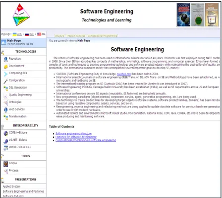
Basic system Case-instruments of support of technology of development of the program systems and their families from reuses are been by the programs of realization of some technological functions, presented on the site main page (Figure 6).
[image:12.595.89.538.301.699.2]The main page of the web site features a list of sections concerning Software Engineering: TECHNOLOGIES, INTEROPERABILITY, TOOLS, PRESENTATIONS AND LEARNING.
Each section contains subsections with keywords that specify the names of the keywords, divided into the main categories, are as following:
TECHNOLOGIES: Component repository; Component development; Assembling reuses: Component con-fguration; DSL generation; Quality engineering; Onto logies;
Web services; Data type’s transformation.
INTEROPERABILITY: CORBA↔ Eclipse: VS.NET ↔ Eclipse; Visual Basic ↔Visual C++. TOOLS: Eclipse, Protégé, CORBA.
PRESENTATIONS: Applied systems; Software and program factories; Software industry systems. EDUCATION: C# and MS.NET framework; Java; Software Engineering.
All sections and subsections include standardized pages, such as an overall theoretical description, that illu-strates the concerned topic (developed with one of the workbench programming environments), a thorough de-scription of the example, and so on. Each page displaying an article on one of the topics of the complex is built using the same template that contains the following main components:
1) The unified header contains the site banner and the title. 2) The current location string.
3) The main menu includes the language panel and links for navigation.
4) The navigation panel, which contains links to various subsections of the current section. 5) The content of the section that includes information about the site authors and developers.
During learning with chosen product lines for their inclusion into ITC complex, the following main criteria were taken into account (with the order their priority, from the most important):
1) Relevance of the topic in question develops the software by engineering discipline, as well as its applica-bility for solving real world problems.
2) Theoretical basis supporting the technology in complex ITC.
3) Relations between the technology and techniques behind other product lines.
4) Simplicity and accessibility of both theoretical and applied aspects of the technology for a sufficiently wide audience, including students and lecturers of Ukrainian universities.
For realization AS from components are used operations of components algebra ІТC of next operations: link AS (A, In, С)—assembling components A, In, С;
config SAS (Al1, Bl1, Cl1 (InidlA, InidlB, InidlC))—configuring, A, B, C;
Interconect AS (A, B, C, InA, InB, InC)—co-operation union, A, B, C with their interfaces; redevelop AS (InA, InB)—alteration of types of data A, B;
make away AS (A)—to remove component A in AS; Add AS (A, C)—to add A, С to AS;
Insert F ⇒AS—to insert F from AS and so on.
Its actions are filled with new operations in ІТC, related to the management of variability, choice of prepared components, collection of them in the complex structures of the program systems, by replacements of unneces-sary artifacts and estimation of quality of components and AS from them.
By this task for disciplines of Software Engineering learning of the students KNU and MIPT, they create dif-ferent artifacts of advanced and graduate studies, placing them into repository ІТC and providing assembling components in the new structures AS. In the complement of the ІТC come in experimental factory of the pro-grams, developed by students for implementation on her of facilities of the Java teaching, C#, Basic VS.Net and the bases of SE disciplines on the textbook of Software Engineering. It is needed to tell about development by students of software support of co-operation of the systems between itself and web-services in complex ІТC
[17]-[19].
Acknowledgem
ents
CASE-tools in question are developed by the students and graduates in their advanced and graduate studies by placing them into the ІТC repository and providing assembling components in the new AS structures. Together with the ІТC, comes an experimental factory of the programs, developed by students to assist in their studies on Java, C#, Basic, VS.Net and the basics of SE disciplines. Software support of co-operation between the systems and web-services in the ІТC was developed by the students A. Оstrovski, I. Radetskiy, as well.
References
[1] Lavrischeva, K.M. (2009) Compositional Programming: Theory and Practice. Cybernetics and Systems Analysis, 45, 845-853.
[2] Grischenko, V. (2007) Object-Component Designing Method for Software Systems. In: Problems in Programming, Vol. 2, Akademperiodika, Kiev, 113-125. (in Ukrainian)
[3] Lavrischeva, E. and Grischenko, V. (2009) Assembly Programming. Basics of Software Industry. 2nd Edition, Nauko-va Dumka, Kiev, 371 p. (in Russian)
[4] Lavrischeva, K. (2010) Formal Fundamentals of Component Interoperability in Programming. Cybernetics and
Sys-tems Analysis, 46, 639-652. (in Russian)
[5] Lavrischeva, K.M. and Stenyashin, A. (2012) Approach to Transforming General Data Types According to ISO/IEC
11404 Standard for Use in Heterogeneous Environments. 2nd International Conference on High Performance Compu-ting, Kyiv, Ukraine, 8-10 October 2012, 227-234. (in Russian)
[6] Lavrischeva, K., Kolesnik, A. and Stenyashin, A. (2013) Object-Component Design of Software Systems. Theoretical and Applied Problems. Visnyk Kiev National University (KNU) of Taras Shevchenko, Series Phys.-Math. Sciences, Special issue, 103-118. (in Ukrainian)
[7] Kolesnyk, A. (2013) Models and Methods Development of System Families of Variant Program Systems. Abstract of
Ph.D. Dissertation, KNU, Kiev, 22 p. (in Ukrainian)
[8] Lavrischeva, E. (2006) Programming Methods. Theory, Engineering, Practice. Naukova Dumka, Kiev, 451 p. (in Rus-sian)
[9] Lavrischeva, E. (2011) Interaction Models of Programs, Systems, and Operational Environments. In: Problems in
Pro-gramming, Vol. 3, Akademperiodika, Kiev, 13-24. (in Ukrainian)
[10] Ostrovski, A. (2011) Approach to Interconnection Support between Java and MS.NET Programming Environments. In:
Problems in Programming, Vol. 2, Akademperiodika, Kiev, 37-44. (in Russian)
[11] Radetskyi, I. (2011) One of Approaches to Maintenance Interconnection Environments Visual Studio and Eclipse. In:
Problems in Programming, Vol. 2, Akademperiodika, Kiev, 45-52. (in Ukrainian)
[12] Lavrischeva, E., Ostrovski, A. and Radetskyi, I. (2012) Approach to E-Learning Fundamental Aspects of Software En-gineering. 8th International Conference ICTERI-2012 ICT in Education, Research and Industrial Applications, Kher-son, 6-10 June 2012, 121-130.
[13] Lavrischeva, E. and Ostrovski, A. (2013) General Disciplines and Tools for E-Learning Software Engineering. 9th
In-ternational Conference ICTERI-2013 ICT in Education, Research and Industrial Applications, Kherson, 19-22 June
2013, 212-229.
[14] Lavrischeva, K., Aronov, A. and Dzubenko, A. (2013) A Programs Factory—A Conception of Knowledge
Representa-tion of Scientific Artifacts from Standpoint of Software Engineering. Computer and Information Science, Canadian
Center of Science and Education, 6, 21-28.
[15] Lavrischeva, E. and Ostrovski, A. (2013) New Theoretical Aspects of Software Engineering for Development Applica-tions and E-Learning. Journal of Software Engineering and Applications, 6, 34-40.
http://dx.doi.org/10.4236/jsea.2013.69A004
[16] Slabospickaya, O. (2014) Feature Model of Software Product Line Enhancing to Enable Product Adaptability. In:
Bul-letin of University of Kiev, Series: Physics & Mathematics, Special Issue, Kiev, 151-158. (in Ukrainian)
[17] Slabospitskaya, O. and Kolesnyk, A. (2012) The Model for Enhanced Variability Management Process in Software Product Line. In: Mayr, H.C., Kop, C., Liddle, S. and Ginige, A., Eds., Information Systems: Methods, Models and
Ap-plications, Revised Selected Papers of 4th International United Information Systems Conference (UNISCON 2012),
Yalta, 162-171.
[18] Lavrischeva, E., Zinkovich, V., Kolesnik, A., et al. (2012) Instrumental and Technological Complex for Development and Learning Design Patterns of Software Systems. State Intellectual Property Service of Ukraine, Copyright Registra-tion Certificate No. 45292, 103 p. (in Ukrainian)
[19] Lavrischeva, E.M. (2013) Software Engineering Computer Systems. Papadigms, Technologies, CASE-Tools. Naukova