© 2018, IRJET | Impact Factor value: 6.171 | ISO 9001:2008 Certified Journal | Page 263
Adaptive Technique for Transformer Fault Analysis
Gaurav D. Mitkar
1, Dhammaratna B. Waghmare
21
PG Scholar, Electrical Engineering Department, Shri Sai College of Engineering & Technology, Bhadrawati
2Head of Department, Electrical Engineering Department, Shri Sai College of Engineering & Technology,
Bhadrawati, Maharashtra, India
---***---Abstract -
A power transformer is one in every of theforemost vital units in power networks; therefore, fault diagnosing of transformers is kind of vital. During this projected approach, the frequency-response analysis, deemed as an appropriate diagnostic methodology for electrical of a power transformer, is utilized to form a choice over a defective section. To take care of band frequency responses of every section, an artificial spectral analysis is projected, that augments low- and medium-frequency elements, and equalizes the frequency intervals of a ensuing combined curve by a log-frequency interpolation. What is more, for discriminating a defective section through computing overall amounts of deviation with different phases, the two well-known criteria and three projected criteria area unit examined with experiment knowledge.
Also the wavelet transform could be a powerful tool within the analysis of the power transformer device transient phenomena due to its ability to extract data from the transient signals at the same time in each the time and frequency domain. This technique presents a completely unique technique for correct discrimination between an indoor fault and a magnetizing influx current within the power transformer by combining wavelet transforms with threshold logic for spectral energy calibration of transient signals. The wavelet transform is first of all applied to decompose the differential current signals of the power transformer device into a series of elaborate ripple elements. The spectral energies of the ripple elements area unit calculated for threshold logic based mostly fault arrangement planning. The simulated results conferred clearly show that the planned technique will accurately discriminate between an indoor faults like primary aspect fault and secondary aspect faults. The planned technique then compared with quick Fourier transform analysis approach. That each techniques used in MATLAB Simulink package for analysis of electrical device fault analysis.
Key Words: Transformer fault analysis, wavelet transform, threshold logic.
The demand for a reliable provide of current for the exigency of recent world in every and each field has enhanced significantly requiring nearly a no-fault operation of power systems. Power transformers square measure a category of terribly dear and important parts of electrical power systems. The crucial objective to mitigate the frequency and length of unwanted outages associated with power electrical
device puts a high pointed demand on power electrical device protecting relays to work immaculately and freakishly. The high pointed demand includes the necessities of reliability related to no false tripping, and operative speed with short fault detection and clearing time.
Protection of enormous power transformers could be a terribly difficult drawback in installation relaying. The protecting system embody devices that acknowledge the existence of a fault, indicates its location and sophistication, find another abnormal fault like operative conditions and starts the inceptive steps of gap of circuit breakers to disconnect the faulty instrumentation of the facility system. Recent development within the field of digital natural philosophy and signal process created it doable to make micro chip primarily based relays which give a viable various to the mechanical device and solid state relays. micro chip primarily based relays use package for decoding signals and implementing logic. With the arrival of micro chip numerous digital algorithms are developed and with success enforced for power electrical device protection.
There are issues that are peculiar to electrical device, that don't seem to be encountered in alternative things of power grid. one among the most important downside is that the massive magnetizing influx current, whose magnitude is as high as internal fault current and should cause false tripping of the breaker. A typical differential relay operational on the idea of measure and analysis of currents at either side of the electrical device can’t avoid the trip signal throughout influx condition.
The protection of power electrical device has become a difficult job because of the somewhat similar development ascertained throughout influx and internal fault prevalence. conjointly the kind of faults and its locations varies plenty as single – part to ground fault, 2 part to ground fault, 3 part to ground fault, put down flip fault, external line to line fault etc. There are issues that are peculiar to electrical device, that don't seem to be encountered in alternative things of power grid. One among the most important issues is that the massive magnetizing influx current, whose magnitude is as high as internal fault current and should cause false tripping of the breaker.
© 2018, IRJET | Impact Factor value: 6.171 | ISO 9001:2008 Certified Journal | Page 264
2. Proposed Methodology
Fig -3: Generalized block diagram of propose approach Figure 3 show the block diagram of proposed approach. Explanation of block is as follow:
2.1. put power supply: This is the power supply for transformer which is fed to transformer primary side. In proposed approach three phase generator or alternator rated at 600 MVA, phase to phase voltage of 153 KV, base voltage 34.5 kv is used to supply transformer which is on testing condition.
2.2. Fault simulator: In proposed approach fault takes place at both primary side and secondary side winding of transformer. There are total three types of transformer winding faults was simulated. These faults are phase to phase winding fault, phase to ground winding fault, and three phase short circuit winding fault. These three types of fault takes place in both primary and secondary side of transformer on each phase of transformer. The detail of each fault are as follows:
2.2.1. Phase to phase winding fault: If any one conductor of primary side or secondary side of winding of transformer connect with another phase of primary or secondary winding due to the insulator failure between two phases or due to temperature effect then such type of faults are called as phase to phase winding fault.
2.2.2. Phase to ground fault: If any one of conductor of primary or secondary side winding short or touch with body of transformer or transformer core due to insulator failure then such fault is called as phase to ground winding fault. 2.2.3. Three phase winding fault or short circuit: If three phase of winding of primary or secondary side short circuit with each other due to temperature rise of transformer or insulator failure of transformer winding during excessive overloading condition.
Table-1: Fault type and fault simulated in proposed approach using MATLAB fault simulator
Sr
No Name of fault Condition of faults on primary side or secondary side 1 Phase to phase winding
fault AB, BC & AC
2 Phase to Ground winding
fault AG, BG, CG
3 Three phase short circuit ABC or ABCG
Table-2: Transformer model specification of proposed approach
Transformer parameter Specification
MVA Rating 50 MVA
Primary winding voltage 10 KV Secondary winding voltage 440 V Primary winding connection Delta
Secondary winding
connection Star with solid grounded
Frequency 50Hz
Primary & secondary
winding resistance 0.02 Pu
Primary & secondary
winding inductance 0.08 pu
[image:2.595.305.566.273.488.2]Magnetizing resistance Rm 500 pu Magnetizing inductance Lm 500 pu
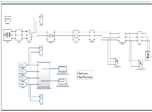
Fig -4: Main matlab simulation model of project implementation
[image:2.595.308.575.519.716.2]© 2018, IRJET | Impact Factor value: 6.171 | ISO 9001:2008 Certified Journal | Page 265 This project implementation will be done using MATLAB
Simulink software. The major blocks will be design in MATLAB 2015 simulink as follows:
Simulation of power system using simpower system toolbox.
Simulation of transformer using sim power system toolbox.
Simulation of fault analysis system for transformer using simpower system toolbox.
Simulation of frequency analysis system for fault analysis using DSP (Digital Signal Processing) toolbox.
Simulation of different fault in transformer for analysis.
Simulate transformer parameter (voltage, current, impedance, frequency) sensing unit using generalized blocks in MATLAB.
Simulation of wavelet transform based multi-resolution analysis and spectral energy calibration subsystem using DSP toolbox, wavelet transform toolbox and general mathematics toolbox.
[image:3.595.31.566.65.785.2] Simulation of Fast Fourier transform toolbox using DSP toolbox.
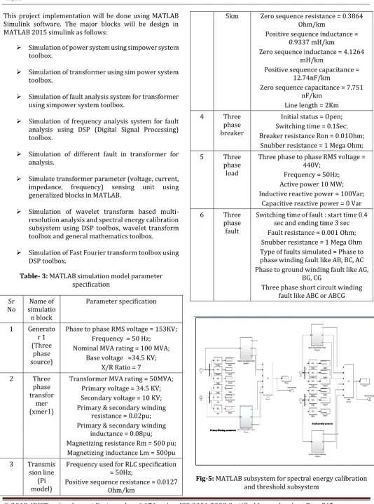
Table- 3: MATLAB simulation model parameter specification
Sr
No simulatioName of n block
Parameter specification
1 Generato
r 1 (Three
phase source)
Phase to phase RMS voltage = 153KV; Frequency = 50 Hz;
Nominal MVA rating = 100 MVA; Base voltage =34.5 KV;
X/R Ratio = 7
2 Three
phase transfor
mer (xmer1)
Transformer MVA rating = 50MVA; Primary voltage = 34.5 KV; Secondary voltage = 10 KV; Primary & secondary winding
resistance = 0.02pu; Primary & secondary winding
inductance = 0.08pu;
Magnetizing resistance Rm = 500 pu; Magnetizing inductance Lm = 500pu
3 Transmis
sion line (Pi model)
Frequency used for RLC specification = 50Hz;
Positive sequence resistance = 0.0127 Ohm/km
5km Zero sequence resistance = 0.3864 Ohm/km
Positive sequence inductance = 0.9337 mH/km
Zero sequence inductance = 4.1264 mH/km
Positive sequence capacitance = 12.74nF/km
Zero sequence capacitance = 7.751 nF/km
Line length = 2Km
4 Three
phase breaker
Initial status = Open; Switching time = 0.1Sec; Breaker resistance Ron = 0.01Ohm;
Snubber resistance = 1 Mega Ohm;
5 Three
phase load
Three phase to phase RMS voltage = 440V;
Frequency = 50Hz; Active power 10 MW; Inductive reactive power = 100Var;
Capacitive reactive power = 0 Var
6 Three
phase fault
Switching time of fault : start time 0.4 sec and ending time 3 sec Fault resistance = 0.001 Ohm; Snubber resistance = 1 Mega Ohm Type of faults simulated = Phase to phase winding fault like AB, BC, AC Phase to ground winding fault like AG,
BG, CG
Three phase short circuit winding fault like ABC or ABCG
© 2018, IRJET | Impact Factor value: 6.171 | ISO 9001:2008 Certified Journal | Page 266 Figure 5 shows the spectral energy calibration subsystem in
which three phase primary and secondary voltage and current (rms) utilized for calibration of detail and approximate coordinator of primary side and secondary side three phase voltage and current i.e. total 12 parameters are input for that system. From primary side three phase current and three phase voltage while from secondary side three phase secondary voltage and current fed to wavelet multi-resolution analysis filtering bank. In which HAAR mother wavelet used for multi-resolution analysis on each primary and secondary phase voltage and current. Multi-resolution analysis take place upto 4 level. That is we get detail 1, detail 2, detail 3, detail 4 and Approximate A4 for each three phase primary and secondary current and voltage signal shown in figure 7. Then after approximate signal of each three phase voltage and current of primary side and secondary side fed to spectral energy calibration subsystem shown in figure 6. Then spectral energy of each phase current and voltage both primary and secondary side compare with normal condition spectral energy. For voltage phases, if spectral energy of actual phase voltage is less than set threshold value then it consider as fault case on that individual phase due to primary side or secondary side fault (direct fault or fault reflect from other side of transformer). For current phases, if spectral energy of actual current phase is greater that set threshold value of spectral energy which set during normal condition of transformer then it consider as fault condition.
Fig-6: Wavelet multi-resolution analysis for spectral energy calibration subsystem using MATLAB Simulink If anyone phase spectral energy below for voltage phases or above for current phases of transformer then that time comparison subsystem provide answer 1 otherwise provide answer 0. If anyone phase answer becomes 1 then it consider as fault condition on that side of transformer. The logic answer generated by using OR gate. If anyone phase answer becomes 1 then OR gate answer also 1. OR gate employ on both side transformer voltage and current subsystem.
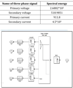
Table-4: Spectral energy threshold values
Name of three phase signal Spectral energy
Primary voltage 2.6882*105
Secondary voltage 518.9851
Primary current 911.8
Secondary current 4.5*105
[image:4.595.37.284.408.597.2]Fig-7: wavelet multi-resolution analysis on phase A
Figure 8 shows the subsystem for comparisons of spectral energy of each phase (primary side and secondary side) voltage and currents in which greater than or less than equal to blocks are used and connect each block with spectral energy constant value which calibrate at normal condition of transformer operation.
[image:4.595.312.557.525.701.2]© 2018, IRJET | Impact Factor value: 6.171 | ISO 9001:2008 Certified Journal | Page 267 4.1. RESULTS FROM FFT ANALYSIS
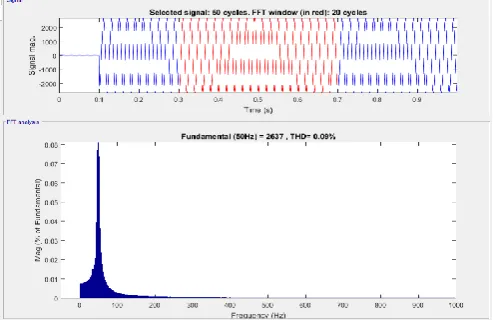
Fig-9: FFT analysis of phase A current signal of transformer primary side when phase to phase winding
[image:5.595.36.284.116.299.2]fault occurs at transformer primary side
Fig-10: FFT analysis of phase B voltage signal of transformer secondary side when phase to phase (AB)
winding fault occurs at transformer primary side
[image:5.595.310.559.284.449.2]Fig-11: FFT analysis of phase A current signal of transformer primary side during normal condition
Fig-12: FFT analysis of phase B current signal of transformer secondary side during normal condition
Fig-13: FFT analysis of phase A voltage signal of transformer secondary side during short circuit occurs in
secondary side of transformer
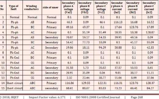
Figure 9 to figure 13 shows the FFT windows for three phase voltage and currents for different fault conditions. Using powergui block in power system FFT analysis done on primary side three phase voltage and current. Also secondary side three phase voltage and current signal employ to FFT analysis for different fault conditions. In this window we calibrate total harmonics distortion of three phase voltage and current for primary side and secondary side.
[image:5.595.38.286.353.516.2] [image:5.595.36.284.570.736.2]© 2018, IRJET | Impact Factor value: 6.171 | ISO 9001:2008 Certified Journal | Page 268 Table-5: FFT Analysis on primary side of transformer
Sr
No Type of fault conductorsWinding side of xmer
Primary phase A voltage
(Va1)
Primary phase B voltage
(Vb1)
Primary phase C voltage (Vc1)
Primary phase A current (Ia1)
Primary phase B current (Ib1)
Primary phase C current (IC1)
1 Normal Normal Normal 0.1 0.1 0.09 0.1 0.1 0.09
2 Ph-ph AB Primary 116.04 16.66 16.51 33.07 42.76 0.09
3 Ph-ph BC Primary 17.76 124.2 17.84 0.1 31.61 40.85
4 Ph-ph AC Primary 18.54 18.37 129.06 42.45 0.1 32.7
5 Ph-ph AB Secondary 33.4 36.62 0.09 24.26 35.06 56.91
6 Ph-ph BC Secondary 0.1 34.74 40.62 55.13 23.77 34.41
7 Ph-ph AC Secondary 30.08 0.1 35.39 36.7 60.45 25.24
8 Ph-Gnd AG Primary 0.11 0.1 0.1 0.1 0.1 0.09
9 Ph-Gnd BG Primary 0.1 0.1 0.09 0.1 0.1 0.09
10 Ph-Gnd CG Primary 0.1 0.11 0.1 0.1 0.1 0.1
11 Ph-Gnd AG Secondary 27.5 10.45 8.62 27.42 34.76 0.09
12 Ph-Gnd BG Secondary 9.02 28.21 11.12 0.1 25.71 32.76
13 Ph-Gnd CG Secondary 11.05 8.99 28.06 35.39 0.1 27.77
14 circuit Short ABC Primary 116.04 124.2 129.06 37.86 36.37 35.99
15 circuit Short ABC Secondary 49.31 46.56 57.3 36.77 35.01 34.37
Table-6: FFT Analysis on secondary side of transformer
Sr
No Type of fault conductorsWinding side of xmer
Secondery phase A voltage
(Va2)
Secondary phase B voltage
(Vb2)
Secondary phase C voltage (Vc2)
Secondar y phase A
current (Ia2)
Secondary phase B current (Ib2)
Secondary phase C current (Ic2)
1 Normal Normal Normal 0.1 0.09 0.1 0.1 0.1 0.09
2 Ph-ph AB Primary 46.3 0.09 46.4 116.13 16.68 16.52
3 Ph-ph BC Primary 49.16 49.37 0.1 17.64 123.76 17.89
4 Ph-ph AC Primary 0.1 51.19 51.49 18.55 18.38 128.87
5 Ph-ph AB Secondary 70.07 19.17 14.55 39.91 49.16 0.09
6 Ph-ph BC Secondary 16.42 77.73 18.89 0.1 41.17 55.09
7 Ph-ph AC Secondary 19.06 18.11 94.29 50.88 0.1 42.35
8 Ph-Gnd AG Primary 0.1 0.09 0.1 0.1 0.1 0.09
9 Ph-Gnd BG Primary 0.1 0.09 0.1 0.1 0.1 0.09
10 Ph-Gnd CG Primary 0.1 0.09 0.1 0.1 0.1 0.09
11 Ph-Gnd AG Secondary 31.58 1.73 20.82 37.57 10.53 8.61
12 Ph-Gnd BG Secondary 20.91 31.09 0.06 9.01 38.17 11.11
13 Ph-Gnd CG secondary 2.32 22.44 38.77 11.06 8.99 37.96
14 Short circuit ABC Primary 116.86 129.55 122.31 116.31 123.76 128.37
[image:6.595.39.561.466.793.2]© 2018, IRJET | Impact Factor value: 6.171 | ISO 9001:2008 Certified Journal | Page 269 4.2. Results from spectral energy based subsystem
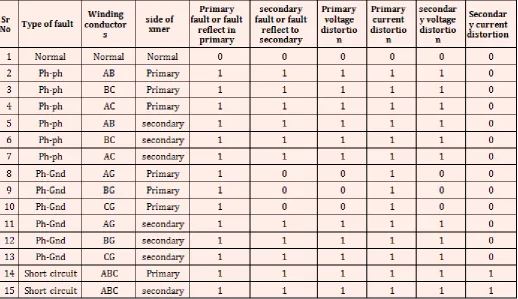
Table- 7: Spectral energy based analysis and classification of fault occurs in transformer
Sr
No Type of fault
Winding conductor
s
side of xmer
Primary fault or fault
reflect in primary
secondary fault or fault
reflect to secondary
Primary voltage distortio
n
Primary current distortio
n
secondar y voltage distortio
n
Secondar y current distortion
1 Normal Normal Normal 0 0 0 0 0 0
2 Ph-ph AB Primary 1 1 1 1 1 0
3 Ph-ph BC Primary 1 1 1 1 1 0
4 Ph-ph AC Primary 1 1 1 1 1 0
5 Ph-ph AB secondary 1 1 1 1 1 0
6 Ph-ph BC secondary 1 1 1 1 1 0
7 Ph-ph AC secondary 1 1 1 1 1 0
8 Ph-Gnd AG Primary 1 0 0 1 0 0
9 Ph-Gnd BG Primary 1 0 0 1 0 0
10 Ph-Gnd CG Primary 1 0 0 1 0 0
11 Ph-Gnd AG secondary 1 1 1 1 1 0
12 Ph-Gnd BG secondary 1 1 1 1 1 0
13 Ph-Gnd CG secondary 1 1 1 1 1 0
14 Short circuit ABC Primary 1 1 1 1 1 1
15 Short circuit ABC secondary 1 1 1 1 1 1
Table 7 shows the result from spectral energy subsystem in which different fault takes place at primary side and secondary side of transformer. Phase to phase winding fault, phase to ground fault and short circuit winding fault simulated in transformer then fed to spectral energy subsystem. Then decision provided by spectral energy subsystem is presented in table 7.
In this proposed approach, the frequency-response analysis, deemed as a suitable diagnostic method for electrical faults of a transformer, is employed to make a decision over a defective phase.
The wavelet decomposition breaks up the signals into both time and frequency, allowing for a more complete and efficient description of each phase current and accurate fault detection
The required calculations are very simple, it is only necessary to perform a wavelet decomposition at level 5 for HAAR mother wavelet.
Also the wavelet transform is a powerful tool in the analysis of the power transformer transient phenomena because of its ability to extract information from the transient signals
simultaneously in both the time and frequency domain. Then after energy of signal calibrate for both normal as well as for fault condition. Then compare energy signal of fault case with normal condition for each phase of transformer primary and secondary side.
Based on energy calibration and comparison of each phase fault condition was analyzed and identified.
But FFT analysis is less effective method than proposed spectral energy based method for fault analysis.
As a possible extension to this work, it would be quite useful to analyze all the possible neural network architectures and to provide a comparative analysis on each of the architectures and their performance characteristics. The possible neural network architectures that can be analyzed apart from back propagation neural networks are radial basis neural network (RBF) and support vector machines (SVM) networks
.
© 2018, IRJET | Impact Factor value: 6.171 | ISO 9001:2008 Certified Journal | Page 270
REFERENCES
[1] Shah, M. B., & Parmar, M. S. (2017). TRANSFORMER PROTECTION USING ARTIFICIAL NEURAL NETWORK.
[2] Kim, J. W., Park, B., Jeong, S. C., Kim, S. W., & Park, P. (2005). Fault diagnosis of a power transformer using an improved frequency-response analysis. IEEE Transactions on Power Delivery, 20(1), 169-178
[4] Wiszniewski, A., & Kasztenny, B. (1995). A multi-criteria differential transformer relay based on fuzzy logic. IEEE Transactions on Power Delivery, 10(4), 1786-1792
[5] Kasztenny, B., Rosolowski, E., Izykowski, J., Saha, M. M., & Hillstrom, B. (1998). Fuzzy logic controller for on-load transformer tap changer. IEEE Transactions on Power Delivery, 13(1), 164-170.
[6] Eissa, M. M. (2005). A novel digital directional transformer protection technique based on wavelet packet. IEEE Transactions on Power Delivery, 20(3), 1830-1836
[7] Kim, J. W., Park, B., Jeong, S. C., Kim, S. W., & Park, P. (2005). Fault diagnosis of a power transformer using an improved frequency-response analysis. IEEE Transactions on Power Delivery, 20(1), 169-178
[8] Wu, T., Tu, G., Bo, Z. Q., & Klimek, A. (2007, November). Fuzzy set theory and fault tree analysis based method suitable for fault diagnosis of power transformer. In Intelligent Systems Applications to Power Systems, 2007. ISAP 2007. International Conference on (pp. 1-5). IEEE.
[9] Naresh, R., Sharma, V., & Vashisth, M. (2008). An integrated neural fuzzy approach for fault diagnosis of transformers. IEEE transactions on power delivery, 23(4), 2017-2024.
[10] Saleh, S. A., & Rahman, M. A. (2005). Modeling and protection of a three-phase power transformer using wavelet packet transform. IEEE Transactions on Power Delivery, 20(2), 1273-1282.
[11] Saleh, S. A., & Rahman, M. A. (2005). Modeling and protection of a three-phase power transformer using wavelet packet transform. IEEE Transactions on Power Delivery, 20(2), 1273-1282.
[12] Liu, Z., Aoran, X., Li, L., & Yi, Z. (2012, September). Inrush current on transformer differential protection affect the analysis and discussion. In Electricity Distribution (CICED), 2012 China International Conference on (pp. 1-3). IEEE.
[13] Liu, Z., Aoran, X., Li, L., & Yi, Z. (2012, September). Inrush current on transformer differential protection
affect the analysis and discussion. In Electricity Distribution (CICED), 2012 China International Conference on (pp. 1-3). IEEE.
[14] Hamilton, R. (2013). Analysis of transformer inrush current and comparison of harmonic restraint methods in transformer protection. IEEE Transactions on Industry Applications, 49(4), 1890-1899.
[15] Kumar, S., & Sreeram, V. (2013, April). Elimination of DC component and identification of inrush current using harmonic analysis for power transformer protection. In TENCON Spring Conference, 2013 IEEE (pp. 151-155). IEEE.
[16] Ahmed, M. R., Geliel, M. A., & Khalil, A. (2013, June). Power transformer fault diagnosis using fuzzy logic technique based on dissolved gas analysis. In Control & Automation (MED), 2013 21st Mediterranean Conference on (pp. 584-589). IEEE.