2018 3rd International Conference on Information Technology and Industrial Automation (ICITIA 2018) ISBN: 978-1-60595-607-7
Simulation Analysis of Centroid Offset of
Electric Drive Bulldozer Based on Recur Dyn
Lun Li, Bofeng Du, Ji Shun Li, Shusheng Chen, Fang Yang
and Dianxing Qi
ABSTRACT
Based on Recur Dyn software, the virtual prototype of D320E electric drive crawler-type bulldozer is built. The dynamic simulation analysis under two different straight-line working conditions of dry sand and clay pavement is carried out. The research results show that the variation law of the mass center of bulldozer with the working resistance under different working conditions. The working stability of the bulldozer can be improved through the reasonable layout of the mass center of bulldozer, which provides a reference for the optimal design of the bulldozer.1
INTRODUCTION
With the development of modern electric drive technology, electric drive technology has made certain progress in construction machinery[1]. But at present, only the D7E bulldozer developed by Caterpillar Company in the United States is on the market[2-3]. The domestic electric bulldozer is still in its infancy. Electric drive construction machinery is an important direction of future development of construction machinery due to its characteristics of flexible layout, simple structure, easy control and wide range of speed change[4].
In the simulation research of the bulldozer crawler chassis, domestic and foreign scholars have done a lot of related types of research. Zhou C K[5] et al. tilted the 10
1
Lun Li, Ji-shun Li, Fang Yang, Henan Key Laboratory for Machinery Design and Transmission System, Henan University of Science and Technology, Luoyang, China Bo-feng Du, School of Mechatronics Engineering, Henan University of Science and Technology, Luoyang, China
degree slope of the tracked vehicle and simulated and compared the dynamics through the soft and hard ground steering process; Zhang Y[6] et al. used the multi-body dynamics simulation software Recur Dyn's tracked vehicle subsystem Track (LM) to establish a multi-body dynamics model of the crawler bulldozer, and simulated the performance of the drive system. Xi-shu WANG[7] et al. carried out simulation research on the force between the drive sprocket, the roller and the track shoe, and provided a theoretical basis for the improved design of the crawler walking device; Zhi-ming Zhang[8] et al. completed the dynamics and kinematics simulation analysis of the bulldozer working device model; Kai CHENG[9] carried out simulation analysis on the walking mechanism of the bulldozer, and proposed structural improvement and optimization measures and extended the service life of the crawler walking system. In order to facilitate the development of electric drive construction machinery and improve the research efficiency[10], this paper takes the D320E electric drive crawler bulldozer as an example to carry out the three-dimensional modeling based on the Track (LM) module of Recur Dyn, a multi-body dynamic analysis software, and also analyzes the change of the whole machine's mass center deviation with the working resistance under different ground conditions. Based on the above research, the dynamic performance of the electric drive bulldozer is obtained, which provides support for the research and development of the electric drive bulldozer[11].
DYNAMIC MODELING
The three-dimensional model of electric bulldozer directly imported into Recur Dyn software which is built in CATIA software. The simplified model of bulldozer is built in Recur Dyn software, which includes car body, shovel, running system and end drive. The main technical parameters of D320E electric drive bulldozer are shown in TABLEI. Taking the wheel center of the right drive wheel of the bulldozer is as the coordinate origin, the forward direction of the bulldozer is the X direction, the vertical ground direction is the Y direction, and the right direction of the vertical vehicle body is the Z direction, which conforms to the right hand rule.
Vehicle Body Model
Because the internal structure of the bulldozer has no effect on its simulation, and the bulldozer itself has many parts, if not simplified, it will increase the workload of Recur Dyn software calculation and affect the efficiency of simulation
TABLE I. MAIN TECHNICAL PARAMERTERS OF D320E ELECTRIC DRIVE BULLDOZER.
parameter Total Weight
(kg)
Gauge (mm)
Wheelbase (mm)
Track shoe width (mm)
Centroid position (mm)
Figure 1. Vehicle body model.
Figure 2. Walking system model.
calculation. Therefore, to remove some of the structure, including the engine, motor, generator, brake box, hydraulic system and cab and other solid models, only need to apply mass and inertia parameters on the relevant parts of the virtual prototype, simplify the model as shown in Figure 1.
Walking System Model
The walking system comprises the driving wheel, the guide wheel, the supporting wheel, the supporting pulley, the crawler, the walking frame and the tensioning device. In addition to the walking frame, the dynamic model of the walking system can be directly established by the Track (LM) module in RecurDyn, and the constraints among the components can be automatically generated, which is convenient for modeling[12]. The carriage is first built in the three-dimensional software and then imported into the simulation software. The walking system model is shown in Figure 2
Blade Model
[image:3.612.197.398.226.324.2]corresponding hydraulic system, so the blade and the corresponding hydraulic system can be simplified. The simplified blade model is shown in Figure 3.
End Drive Model
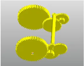
The end drive is an important part of the electric drive bulldozer. It mainly consists of the meshing of three pairs of gears. The pinion drives the big gear to reduces the speed and increases the torque. The power of the first-order pinion is given by the motor. Finally, it is coaxially transmitted through the end gear and the driving wheel. The model established by the Gear module is shown in Figure 4.
[image:4.612.111.481.248.547.2] [image:4.612.117.260.248.369.2]
Figure 3. Blade model. Figure 4. End drive model.
Figure 5. Whole model of electric drive bulldozer. Figure 8. A dynamic in the simulation process of dry sand pavement.
Pavement Model
[image:4.612.333.476.254.367.2]Whole Model of Electric Drive Bulldozer
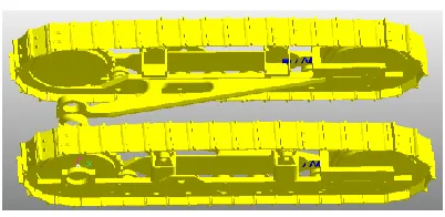
In Recur Dyn, each model is joined together in the form of constraints to make its movement principle and form consistent with the actual work of the bulldozer. The constraints used mainly include rotary pair, fixed hinge, translation pair, ball joint, etc. The vehicle dynamics model is as shown in Figure 5.
SIMULATION ANALYSIS OF WORKING CONDITION
[image:5.612.116.482.308.436.2]The electric drive bulldozer studied in this paper is simulated in two kinds of pavement conditions, both of which are carried out under linear bulldozing conditions. But they have different walking conditions and different bulldozing resistance. When working conditions are analyzed on clay pavement, the working
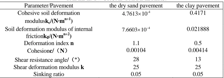
TABLE II. TWOROAD PARAMETERS.
Parameter/Pavement the dry sand pavement the clay pavement
Cohesive soil deformation
moduluskc/(N∙mn+1)
-4
4.7613 10 0.4171
Soil deformation modulus of internal
frictionk∅/(N∙mn+2)
4
7.6603 10 0.021888
Deformation index n 1.1 0.5
Cohesionc/(N) 0.00104 0.00414
Shear resistance angle/(º) 28 13
Shear deformation modulus k 25 25
Sinking ratio 0.05 0.05
environment is bad. In order to improve the simulation efficiency while achieving a certain simulation accuracy, the following assumptions are made on the simulation analysis[13]:
1)Except for the track tensioning device and the two types of pavements are elastic components, the remaining components are rigid components, and the relevant stiffness coefficients are only set for the motion pairs between the components.
2) Remove parts that have no impact on the simulation, such as oil lines and pressure systems, and convert their quality into connected parts.
Simulation Analysis of Dry Sand Pavement
due to gravity; the 0.5-1s bulldozer gradually accelerates to a certain speed; the bulldozer runs at a constant speed for a period of 1-2s, and the spade gradually enters the soil; 2-12s blade set the depth of the soil to reach the full shovel, the speed has decreased; 12-12.5s bulldozer unloading the soil, stop the operation and the speed drops to zero. The applied drive function is an angular velocity function, and the function is as follows:
=STEP Time, 0.5, 0,1, 5100D STEP Time, 2, 0,12, 2746D STEP Time,12, 0,12.5, 2354D
The working resistance of bulldozer linear bulldozing operation is divided into three same horizontal direction and three same vertical direction. The bulldozer does not shove the soil at 0-2s, that is, the working resistance is zero; the shovel is lowered to a certain depth in 2-12s, and the shovel is full, at this time the resistance reaches from zero to maximum; blade unloading in 12-12.5s, that is, the working resistance is reduced from maximum to zero. The simulation functions of single horizontal direction resistance and single vertical resistance are respectively:
, 2, 0,12, 60707 ,12, 0,12.5, 60707
x
F STEP Time STEP Time ;
, 2, 0,12, 39892 ,12, 0,12.5, 39892
y
F STEP Time STEP Time 。
0 50 100 150 200 250 0 200 400 600 800 1000 1200 ce ntroi d offs et (mm )
working resistance (kN)
0 50 100 150 200 250 -50 -40 -30 -20 -10 0 10 Y-direc ti on ce ntroi d offs et (mm )
[image:6.612.119.486.375.527.2]working resistance (kN)
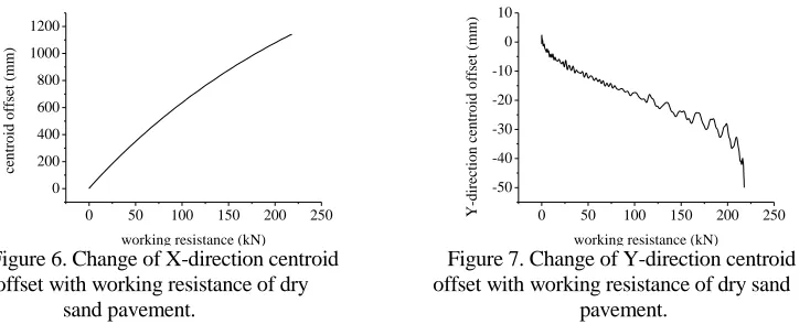
Figure 6. Change of X-direction centroid Figure 7. Change of Y-direction centroid offset with working resistance of dry offset with working resistance of dry sand
sand pavement. pavement.
As shown in Figure 6, the working resistance varies from 0 kN to 218 kN, and the X-direction centroid offset increases from 0 to 1141 mm. That is to say, with the working resistance increases, the forward shift of the center of gravity of the bulldozer is also increasing. It can be seen that with the increase of working resistance, the centroid offset increases, which leads to the phenomenon of bulldozer tail warping, and it is more and more obvious, and even the bulldozer can’t work normally. Figure 8 shows a dynamic in the simulation process of dry sand pavement. It can be seen that the crawler drive wheel has a tendency to sink, and it is very deep, that is, the whole machine has a tail-hanging phenomenon, and the centroid shifts forward, and the simulation The results are consistent.
As shown in Figure 7, the same working resistance varies from 0 to 218 kN, and the Y-direction negative centroid shift increases from 0 to 50 mm, that is, with the working resistance increases, the downward shift of the center of mass of the bulldozer is also increasing. It can be seen that as the working resistance increases, the height of the bulldozer's center of mass is getting lower and lower, which improves the working stability of the bulldozer. However, compared with the bulldozer's centroid offset in the X-direction, it has little effect on the stability of its operation.
In summary, the forward shift of the bulldozer's centroid (the X positive direction) has the greatest impact on the stability of the bulldozer, which is consistent with the actual situation. Under the condition of straight bulldozing work,
-20 0 20 40 60 80 100 120 140 160 0 200 400 600 800 ce n tro id o ff set (mm)
working resistance (kN)
-20 0 20 40 60 80 100 120 140 160 -60 -50 -40 -30 -20 -10 0 Y-direc ti on ce ntroi d offs et (mm )
[image:7.612.105.247.412.519.2]working resistance (kN)
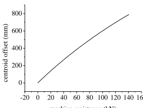
Figure 9. Change of X-direction centroid Figure 10. Change of Y-direction centroid offset with working resistance of clay offset with working resistance of clay
pavement. Pavement.
Simulation Analysis of Clay Pavement
Similarly, when the bulldozer is simulated in clay pavement environment, the processes and drive function set is the same as that on the dry sand pavement. Because of the different road conditions, the working resistance of bulldozers is different. The simulation functions of single horizontal resistance and single vertical resistance are as follows:
, 2, 0,12, 40030 ,12, 0,12.5, 40030
x
F STEP Time STEP Time ;
, 2, 0,12, 24433 ,12, 0,12.5, 24433
y
F STEP Time STEP Time 。
Similarly, in order to study and analyze the change of the center of mass of the bulldozer under clay pavement with the cutting depth, and the corresponding curves are extracted. Figure 9 shows the change of the forward displacement of the bulldozer's centroid with the working resistance during the bulldozing operation on clay pavement. Figure 10 shows the change of the downward displacement of the bulldozer's centroid with the working resistance during the bulldozing operation on clay pavement.
From the Figure 9 and Figure 10, the working resistance varies from 0 to 41 kN, the X-direction centroid offset increases from 0 to 788 mm, and the Y-negative centroid offset increases from 0 to 51 mm, that is, with the working resistance of the blade increases, the forward offset and downward offset of the bulldozer's center of mass are also getting larger and larger. It can be seen that the offset trend of center of mass of bulldozer on the clay pavement is the same as that on the dry sand pavement. But compared with the dry sand pavement, the change of center of mass deviation(including the X direction and the Y direction) of bulldozer under the clay pavement is not so obvious, which shows that the phenomenon of tail warping of bulldozer on the clay pavement is not obvious, which can also be seen in the simulation process. The reason for this phenomenon is that the soil composition of the dry sand pavement and the clay pavement is different, including soil gravity, moisture, cohesion and so on. In the shovel soil, the resistance of the shovel blade on the two pavement is quite different, that is to say, the cutting resistance of shovel blade on the dry sand pavement is larger, which leads to the working resistance on the dry sand pavement is also larger, and the phenomenon of tail warping is more obvious.
CONCLUSIONS
With the depth of cutting increases, that is, with the working resistance increases, the forward displacement of the bulldozer's center of mass becomes larger and larger, and the downward shift of the center of mass is also larger and larger. However, the forward displacement of the bulldozer's center of mass has a greater impact on the stability of the bulldozer. In order to avoid the phenomenon that the bulldozer is unstable and more and more serious and the reasonable arrangement of the center of gravity of the bulldozer can make the grounding pressure uniform, thus improving the working stability of the bulldozer.
ACKNOWLEDGMENTS
This work is supported by Luoyang Science and Technology Major Project (No. 2017(04)) and the Henan Province Science and Technology Major Project (N0.161100210900).
REFERENCES
1. Wen-jia LI, An-lin Wang, Xiao-tian LI, et al. Voltage Transformation Control Method for
Traction Dynamic Characteristic Match of Electric Drive Bulldozer[J].Journal of Tongji University ((Natural Science), 2015, 43(6):904-909.
2. Song-shan Shi, Tao LI, De-wen Kong. Research on Control Simulation of electric drive bulldozer
curve operation[J].construction machinery, 2012, 43(8):10-14.
3. Sekour M, Hartani K, Draou A, et al. Sensorless Fuzzy Direct Torque Control for High
Performance Electric Vehicle with Four In-Wheel Motors[J]. Journal of Electrical Engineering & Technology, 2013, 8(3):530-543.
4. Ye Zheng, Qun-zhang Tu, Ming Pan, et al. Modeling and motion simulation of electric drive
track bulldozer prototype[J].Equipment Manufacturing Technology, 2013(9):22-24.
5. Zhou C K, Huang Y Y, Ni L. The Dynamics Simulation of Tracked Vehicles on the Hard and
Soft Ground Based on the Recur Dyn[J]. Advanced Materials Research, 2013, 842:351-354.
6. Zhang Y, Cheng K, Zuo P, et al. Research on the simulation of the driving system of crawler
bulldozer[C].International Conference on Transportation, Mechanical, and Electrical Engineering. IEEE, 2011:703-706.
7. Xi-shu Wang, Yu-feng Shen. Dynamics simulation analysis of crawler walking mechanism of
caterpillar bulldozers based on ADAMS[J]. Journal of Shandong University of Technology (Natural Science Edition), 2012, 26(3):34-37.
8. Zhi-ming Zhang, Jin-yi Lian, Kai Cheng. Simulation and Optimization of Bulldozer Working
Device Based on Virtual Prototype[J]. Construction mechanization, 2015(7):38-41.
9. Kai Cheng, Xiao-long Xu, Yu-wen Han, et al. Simulation on walking mechanism of Crawler
wetland series bulldozers[J]. Chinese Journal of Construction Machinery, 2013, 11(4): 331-336.
10. Ke Huang, The Research of Electric drive system for High-power bulldozers[D].Chang'an
University, 2015.
11. Yao-juan Zhang, Kai Cheng. Simulation of Walking System of Crawler Bulldozer in Bulldozing
Steering Condition[J].Journal of Beihua University (Natural Science), 2015, 16(5):677-681.
12. Jun Wang, Da-gang Sun, Yong Song, et al. Analysis Of Shocking Characteristics for Rubber
Buffer On Crawler Tractor[J].Mechanical Design &Manufacture, 2015(2):19-20
13. 13Jian-chun Wang, Ji-ming Gao. Differential steering mechanism of crawler bulldozer[J].