5th International Scientific and Business Conference—Future Engineering 2019 ISBN: 978-1-60595-632-9
Naturally Parallel Measuring System Based
on FPGA Hardware
Jacek Długopolski
1and Maria Richert
2ABSTRACT
The FPGA (Field Programmable Gate Array) technology, usually a little unnoticeable, almost from the very beginning is developed simultaneously with the microprocessor technology. The possibility for the system designer or end user to influence the internal structure of the integrated circuit gives unattainable possibilities of building plastic and fully massively parallel systems that fit in almost one integrated circuit. This fact allows, among others for building fully parallel multi-point measuring systems. This manuscript presents the architecture proposal for such an FPGA-based exemplary multichannel measurement system and presents the results of its practical use to study the functioning of a tubular heat exchanger in automotive air-conditioning.
Keywords: FPGA, measurement, parallel, sensors, Air-conditioning.
1. INTRODUCTION
From the very beginning when we are dealing with new technologies and with various kinds of technical devices or we are trying to explore and understand complex systems occurring naturally in nature, then there is always a need to perform various measurements. Thanks to such measurements, we can, for example, determine the technical condition of the device or system, detect structural abnormalities or we can assess the effectiveness of its individual components [1-3]. A smaller problem is in the case, when we need to have measured a physical quantity only in a single point. Such a measurement, which of course takes a certain amount of time, will determine the value of the measured quantity over a given time interval. It is worse when we have to make a __________________
1
Faculty of Computer Science, Electronics and Telecommunications, AGH University of Science and Technology, 30 Mickiewicza Street, 30-059 Cracow, Poland
2
multipoint measurement of some physical quantity, e.g. on the surface of a working mechanical or electronic device. Performing measurements one by one at specific points in the device is a solution, but produces a significant phase error in the time domain. Obtained in this way measurements of the measured quantity at different points of the device are slightly offset from one another in time, which in some cases may lead to erroneous analyzes and conclusions. Therefore, it seems advisable to build multi-point measuring systems that perform independent measurements at all tested points simultaneously (in parallel) without phase shifts in the time domain.
The motivation for adopting and commissioning the solution described here, i.e. a multi-point measuring system that allows to perform many parallel measurements simultaneously at the same time (in this case temperature), was the need to examine the effectiveness of a proposed innovative tube-in-tube type of heat exchanger with torsion channels, intended for car air conditioning systems and implemented as part of the project INNOTECH—K3/IN3/2/225688/ NCBR/14. Car air conditioners operate by using different types of coolant [8-9] in combination with various heat dissipation components. The project concerns a new solution applied in car air conditioners with CO2 as a cooling medium. To build those air conditioners, aluminum alloys has been applied in the construction of their key components [4-7]. Assessment of the efficiency of such an exchanger requires determining the temperature on its surface at a given time simultaneously at many different points along its entire length. Performing individual measurements in a sequential manner one by one would not provide the right data for further analysis. The proposed measurement system is universal and could also be used in other diverse solutions of heat exchangers [10-18].
measurement of physical quantities. Similar approach was presented in 20. The author proposes a system that utilizes parallel multi-channel temperature measurements with digital temperature sensors operating on separate serial 1-Wire buses but the system allows only six digital temperature sensor and uses wireless Bluetooth module to communicate. In our approach, number of sensors depends only on the logical capacity of the FPGA chip and we uses 100 Mb/s Ethernet module for fast and reliable data acquisition. The use of FPGAs is also justified by the fact that they are used in CERN in collision detectors that require extreme detection speed 2122. It also means that in the future it will be very easy to use the concept of the FPGA based measuring device presented here to build very fast multichannel measuring systems. An interesting review of the use of FPGA chips for the construction of sensor systems has been presented in 23. In this article, however, the authors focused more on the construction and optimization of the sensors themselves than on the creation of multi-channel parallel measurement systems. For parallel multi-point temperature measurement, sometimes methods based on infrared radiation are also used. In the article 24, an interesting exemplary system for multipoint temperature measurement of the human body surface is shown. Unfortunately, these types of solutions require direct visibility of the tested object and the measured elements must be protected against reflecting external heat. Therefore, this approach is not appropriate for the applications described in this article.
2. THE CONCEPTION OF THE MEASURING SYSTEM
The details of dynamic processes in industry resulting from the operation of various types of technological solutions, or the essential details of similar dynamic processes occurring during scientific research, often elude researchers or operators of various types of devices and machines. The need for control and monitoring of physical quantities in processes of this type, such as temperature, humidity, pressure, radiation level and other, at many points of the device simultaneously, i.e. without any phase shifts in time—is often a big challenge for constructors and engineers. Especially if the state of the object or process is to be known in a given very short time.
In order for the designed measuring system to be universal and, depending on the needs, easy to adapt, it was decided to build it based on a programmable FPGA chip. The FPGA technology allows an individual end user to configure such a digital circuitry in accordance with its current needs. The FPGA technology allows an individual end user to configure such a digital chip in accordance with its current needs. Additionally, when the need arises, the configuration of the system can be changed any number of times. In other words, the end user influences the current internal logic structure of the integrated circuit. The FPGA chip, depending on the capacity, can consist of tens or hundreds of thousands of individual independent logical blocks, which can be configured and combined into more complex digital structures depending on the needs. This allows to create your own hardware integrated circuit architecture. The internal structure of the FPGA chip can be designed either by means of an electronic scheme or by means of one of the hardware description languages, e.g. VHDL or SystemVerilog. FPGA technology allows for fully hardware, multi-threaded and massively parallel implementation of control algorithms, communication and all other kinds of information processing algorithms. The problem of one computational thread in popular processors and one-chip controllers is only first of the problems. The second important drawback of using processors is the relatively small number of external communication pins they have. This forces the use of a single serial bus that supports multiple sensors by means of their individual addressing. Unfortunately, it additionally increases delays in obtaining data and increases the time phase shifts between the indications of individual sensors. Compared to microprocessors, FPGA chips are characterized by a very large number of useful communication input-output pins which can be used for independent and parallel control of many additional modules and measuring sensors. The advantage of a solution using an FPGA chip with respect to a microprocessor based solution is depicted schematically in Figure 1.
Sensor
Sensor
Sensor
Sensor
Micro Processor
Serial BUS
.. .
Sensor
Sensor
Sensor
Sensor
FPGA
.. .
Serial BUS
Serial BUS
Serial BUS
Serial BUS
S
eri
al
B
U
[image:4.612.205.405.499.569.2]S
Figure 1. Comparision of FPGA and microprocessor usage.
data. At any given time, the processor can communicate with only one sensor. On the right side, the method used in the solution proposed in this article is shown. Instead of the microprocessor, a reconfigurable integrated circuit FPGA was used. Each sensor is connected to other chip pins and thanks to this can use a separate and independent serial bus. In addition, each such sensor is operated by a separate independent part of the FPGA logic. Therefore, the FPGA chip acquires data from all sensors at the same time. Thanks to this, it is possible (within one system) to implement many parallel, simultaneous and independent measurement processes. The hardware (not software) solution proposed here, based on a programmable FPGA integrated circuit allows simultaneous (in the full sense of the word) reading data from all used sensors and making those data available through the network transciver to outside computers in the form of measurement vectors. Thanks to this, the data can then be stored safely and securely or it can be analyzed in real time by any computer connected to the network. Fig.2 shows the concepts of the presented solution.
[image:5.612.201.406.320.410.2]Sensor Sensor Sensor Sensor .. . Network Transceiver Single Sensor Control Unit Single Sensor Control Unit Single Sensor Control Unit Single Sensor Control Unit FPGA Serial BUS Serial BUS Serial BUS Serial BUS S h a p in g D a ta P a c k e ts U n it Network Services And Protocols Unit Communication Interface Communicatiom Protocol PC .. .
Figure 2. The concepts of the FGA configuration.
3. PRACTICAL IMPLEMENTATION OF THE PROPOSED MEASURING SYSTEM
[image:6.612.200.394.224.384.2]As an example of the application of the concept discussed above, a test stand was designed and implemented to compare the efficiency of tubular heat exchangers (type: pipe-in-pipe) for automotive air conditioning systems. The exchanger to be tested is shown schematically in Figure 3. A counter-current variant is used here, in which the cold coolant flows through the central exchanger tube and the hot coolant flows through the outer tube.
Figure 3. Heat exchanger scheme of coolants flow.
One of the research methods during the design of this type of systems was to measure the dynamics of the temperature distribution on the surface of the heat exchanger in order to check its effectiveness and throughput during operation. In order for such measurements to be possible, the model of the proposed solution was further elaborated by deciding on the types of individual components. This is shown in Figure 4.
DS18B20+ Temperature Sensor DS18B20+ Temperature Sensor DS18B20+ Temperature Sensor DS18B20+ Temperature Sensor .. . Ethernet Transceiver RTL 8201CL Single Sensor Control Unit Single Sensor Control Unit Single Sensor Control Unit Single Sensor Control Unit FPGA EP3C25 1-Wire BUS 1-Wire BUS 1-Wire BUS 1-Wire BUS S h a p in g D a ta P a c k e ts U n it Network Services And Protocols Unit Ethernet IP UDP MII Interface Ethernet PC .. .
Figure 4. FPGA based system detailed construction.
[image:6.612.185.406.537.633.2]To ensure simultaneous temperature measurement in many places of the exchanger, it was decided to use: digital temperature sensors DS18B20 + from MAXIM-DALLAS with temperature measurement range from -55 ° C to 125 ° C and the accuracy of 0.5% declared by the manufacturer. In many cases, a better solution is to use digital than analog sensors because of their initial calibration by the manufacturer. Of course, after proper adaptation, analog sensors can still be used in digital systems 25. In our solution, the temperature sensors were connected via the 1-Wire buses to the programmable FPGA EP3C25 Cyclone III logic chip from INTEL to enable their
ł
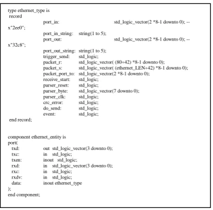
independent and parallel operation. In addition, the Realtek RTL8201CL Ethernet network module has been connected to the FPGA through the MII interface to enable constant and safe transmission of measured temperature values to an external computers. The UDP/IP protocols and broadcast packets were chosen to use.The use of a programmable FPGA chip in place of a processor allowed for easy handling of a large number of sensors. An additional advantage of this solution is the parallel operation of all twenty-two measuring lines, and therefore all measurements take place at the same time. The undoubted disadvantage of this solution is a rather complicated and long-lasting process of creating a configuration description for the FPGA chip. This process is in fact based on developing a logical structure for a dedicated integrated circuit, using the chosen hardware description language, in this case it was the VHDL language. For example, separate hardware components for temperature sensors were created as well as a hardware MII (Medium Independent Interface) protocol component for communication with the RTL8201CL chip. The headings and data types for these components are shown in Figure 5 and Figure 6.
Figure 5. VHDL temperature sensor component interface code.
type ds18b20_type is record
event: std_logic;
temperature_Xdot0: integer range 0 to 255; --czesc calkowita temperature_0dotX: integer range 0 to 15; --czesc ulamkowa temperature_string: string(1 to 7);
end record;
component ds18b20_entity is port(
i_clk: in std_logic; i_ds18b20_bit: inout std_logic; -- 1-Wire i_data: inout ds18b20_type );
Figure 6. VHDL Ethernet sensor component interface code.
The final effect of the built and commissioned controller for the measuring system is shown in Figure 7.
Figure 7. The FPGA controller.
As already mentioned, the DS18B20 + temperature sensors are connected to a controller based on a programmable FPGA Cyclone III system using a 1-Wire digital bus, while the RTL8201CL Ethernet system using a MII bus. In order to achieve the intended functionality of the system, a dedicated internal configuration for FPGA chip was developed using VHDL hardware description language, including implementation of:
type ethernet_type is record
port_in: std_logic_vector(2 *8-1 downto 0); -- x"2ee0";
port_in_string: string(1 to 5);
port_out: std_logic_vector(2 *8-1 downto 0); -- x"32c8";
port_out_string: string(1 to 5); trigger_send: std_logic;
packet_r: std_logic_vector( (80+42) *8-1 downto 0); packet_s: std_logic_vector( (ethernet_LEN+42) *8-1 downto 0); packet_port_to: std_logic_vector(2 *8-1 downto 0);
receive_start: std_logic; parser_reset: std_logic;
parser_byte: std_logic_vector(7 downto 0); parser_clk: std_logic;
crc_error: std_logic; do_send: std_logic; event: std_logic; end record;
component ethernet_entity is port(
txd: out std_logic_vector(3 downto 0); txc: in std_logic;
txen: inout std_logic;
rxd: in std_logic_vector(3 downto 0); rxc: in std_logic;
rxdv: in std_logic; data: inout ethernet_type );
[image:8.612.194.400.397.550.2] hardware 1-Wire communication algorithm for twenty two temperature sensors;
hardware algorithm for reading and processing data from sensors;
communication algorithm with the Ethernet network module via the MII
interface;
hardware version of the UDP/IP network protocol stack to the extent
necessary to obtain communication between the measuring device and PCs collecting data.
[image:9.612.178.415.252.433.2]The final effect of the constructed device is shown below in Figure 8.
Figure 8. The complete FPGA based device for multipoint temperaturemeasurement.
Figure 9. An exemplary screen of a running application.
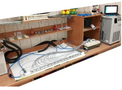
The application allows a real time observation of all measurements being performed, as well as to regularly save them to a text file in CSV format for later processing and analysis. In addition to the above, the application allows the occasional additional correction of temperature sensors indications and let user entering the name of the data file. Adding current measurements to the file can be done manually by pressing the SAVE button at any time, or you can also do it automatically by setting up the "Auto save" option and entering time after which the recording of current measurements will take place automatically. Each measurement vector is saved in a separate line of the text file. The line begins with the date and time of measurement, followed by twenty-two numbers representing measurements from subsequent sensors. The position of the measured value corresponds to the number placed on the temperature sensor from which this value originates. The running measuring station used for the experiments is depicted in Figure 10.
[image:10.612.197.399.510.659.2]The figure shows the running heat exchanger under test, to which probes with temperature sensors of the constructed measuring device were attached. On the surface of the external exchanger tube, the sensors were placed at a distance of 5.88 cm from each other. Constant input temperatures of hot and cold coolants are provided by the Lauda A100 and Lauda WKL 1000 aggregates. Figure 11 shows one of the average temperature distributions measured by the constructed device on the surface of the tested heat exchanger. The chart was generated using the WolframAlpha.
Figure 11. The average temperature distributions chart.
The temperature is marked on the OY axis and the distance from the hot coolant inlet is on the OX axis. Red points show average temperatures from dozens of measurements, and the blue continuous curve is an approximation of the obtained points using the polynomial of degree three model. As you can see the graph shows lower cooling efficiency of the central part of the tested exchanger.
4. SUMMARY
The concept of a multi-point measuring system presented in this article showed in practice the effectiveness and usefulness of FPGA technology for building fully parallel data processing systems. Deprived of phase shifts in the time domain measurements of the surface temperature of the heat exchanger made it possible to visualize its true and accurate heat dissipation characteristics. The presented device can be easily used for continuous monitoring of operating parameters of air conditioning systems in real time, allowing for example detection of sudden partial obstructions in the heat exchanger pipes. Such obstructions are very difficult to detect with other methods.
physical quantities than temperature, e.g. pressure, humidity, light, radiation, etc. In this case, it is enough to connect other digital sensors to the device and replace in the configuration of the FPGA chip the modules responsible for reading the measurements. FPGAs can meet the most demanding operating parameters, as evidenced, for example, by their intense use in CERN collision detectors. On the basis of the presented solution, it would be relatively simple to build a system that performs simultaneous and independent measurements of many different physical quantities, which would enable the detection of complex relationships between various parameters of a particular environment or device.
5. ACKNOWLEDGMENT
The work was supported by project: INNOTECH-K3/IN3/2/225688/NCBR/14.
BIBLIOGRAPHY
1. Mohammed, I., A.R. Abu Talib, M.T.H. Sultan, and S. Saadon. 2016. “Temperature and heat
flux measurement techniques for aeroengine fire test: a review”, IOP Conference Series:
Materials Science and Engineering, 152(1):1–11.
2. Abram, Ch., B. Fond, and F. Beyrau. 2018. “Temperature measurement techniques for gas
and liquid flows using thermographic phosphor tracer particles”, Progress in Energy and
Combustion Science, 64:93–156.
3. Duff, M. and J. Towey. 2010. “Two Ways to Measure Temperature Using Thermocouples
Feature Simplicity, Accuracy, and Flexibility”, Analog Dialogue, 44-10:1–6.
4. Miller, W.S., L. Zhuang, J. Bottema, A.J. Wittebrood, P. De Smet, A. Haszler, and A.
Vieregge. 2000. “Recent development in aluminium alloys for the automotive industry”,
Materials Science and Engineering: A, 280(1):37–49.
5. Sakurai, T. 2008. “The Latest Trends in Aluminum Alloy Sheets for Automotive Body
Panels”, Kobelco Technology Review, 28:22–28.
6. Hirsch, J.R. 2014. “Recent development in aluminium for automotive applications”,
Transactions of Nonferrous Metals Society of China, 24(7):1995–2002, DOI:
10.1016/S1003-6326(14)63305-7.
7. Leszczyńska-Madej, B., M. Richert, A. Wąsik, and A. Szafron. 2018. “Analysis of the
Microstructure and Selected Properties of the Aluminium Alloys Used in Automotive
Air-Conditioning Systems”, Metals, 8(1), 10:1–15, DOI: 10.3390/met8010010.
8. Hall-Geisler, K.: How Automotive Air Conditioning Works. Available from:
https://auto.howstuffworks.com/automotive-air-conditioning.htm [Accessed 30 April 2019].
9. Kuczek, Ł., M. Mroczkowski, and M. Richert. 2017. “CAD supportive in design of
multichannel pipe for automotive application”, Journal of Machine Construction and
Maintenance. Problemy Eksploatacji, 4:71–80.
10. Magadum, A., A. Pawar, R. Patil, and R. Phadtare. 2016. “Review of Experimental Analysis
of Parallel and Counter Flow Heat Exchanger”, International Journal of Engineering
11. Maheshwari, D.A. and K.M. Trivedi. 2015. “A Review on Experimental Investigation of
U-Tube Heat Exchanger using Plain U-Tube and Corrugated U-Tube”, International Journal of
Engineering Development and Research, 3(4):255–259.
12. Osueke, Ch.O., A.O. Onokwai, and A.O. Adeoye. 2015. “Experimental Investigation on the
Effect of Fluid Flow Rate on the Performance of a Parallel Flow Heat Exchanger”,
International Journal of Innovative Research in Advanced Engineering (IJIRAE), 2(6):2349–
2163.
13. Tapre, R.W., Dr. Jayant, and P. Kaware. 2015. “Review on Heat Transfer in Spiral Heat
Exchanger”, International Journal of Scientific and Research Publications, 5(6):1–5.
14. Ahire, S., P. Shelke, B. Shinde, and N. Totala. 2014. “Fabrication and Analysis of Counter
Flow Helical Coil Heat Exchanger”, International Journal of Engineering Trends and
Technology (IJETT), 15(5):2231–5381.
15. Mukeshkumar, P.C., J. Kuma, S. Suresh, and K. Praveen. 2012. “Experimental study on
parallel and counter flow configuration of a shell and helically coiled tube heat exchanger
using Al2O3/water nanofluid”, Journal of Materials and Environmental Science, 3(4):766–
775.
16. Hasan, M.I., A. Muhsin, A. Rageb, and M. Yaghoubi. 2012. “Investigation of a Counter Flow
Micro-channel Heat Exchanger Performance with Using Nanofluid as a Coolant”, Journal of
Electronics Cooling and Thermal Control, 2:35–43.
17. Kragh, J., J. Rose, T.R. Nielsen, and S. Svendsen. 2007. “New counter flow heat exchanger
designed for ventilation systems in cold climates”, Energy and Buildings, 39:1151–1158.
18. Gupta, P. and M.D. Atrey. 2000. “Performance evaluation of counter flow heat exchangers
considering the effect of heat in leak and longitudinal conduction for low-temperature
applications”, Cryogenics, 40(7):469–474.
19. Pantoli, L., M. Muttillo, T. de Rubeis, I. Nardi, V. Stornelli, and G. Ferri. 2017. “Digital
Multi-Probe Temperature Monitoring System for Long-Term on Field Measurements”,
Eurosensors Conference, Paris (France), 3–6 September 2017, Proceedings, 1(4), 596, DOI:
10.3390/proceedings1040596.
20. Wojtkowski, W. 2017. “Power semiconductor devices temperature monitoring system”,
Zeszyty Naukowe Wydziału Elektrotechniki i Automatyki Politechniki Gdańskiej, 54:232–236.
21. Musa, L. 2008. “FPGAs in high energy physics experiments at CERN”. 2008. International
Conference on Field Programmable Logic and Applications, Heidelberg (Germany), 8–10 September 2008. IEEE, DOI: 10.1109/FPL.2008.4629896.
22. Pernegger, H. 2015. “The Pixel Detector of the ATLAS experiment for LHC Run-2”, Journal
of Instrumentation, 10(15):C06012.
23. de la Piedra, A., A. Braeken, and A. Touhafi: “Sensor Based on FPGAs and Their
Applications: A Survey”, Sensors, 12(9):12235–12264.
24. Chen, J., J.-P. Wang, T.-Y. Shen, D.-X. Xiong, and L.-Q. Guo. 2017. “High Precision
Infrared Temperature Measurement System Based on Distance Compensation”, ITM Web of
Conferences, 12:03021, DOI: 10.1051/itmconf/20171203021.
25. Moghavvemi, M., K.E. Ng, C.Y. Soo, and S.Y. Tan. 2005. “A reliable and economically
feasible remote sensing system for temperature and relative humidity measurement”, Sensors