5th International Scientific and Business Conference—Future Engineering 2019 ISBN: 978-1-60595-632-9
Analysis of the Working Time of Assembly
Railway Pantograph
Katarzyna Łyp-Wrońska
1, Arkadiusz Wolski
1and Marzanna Książek
1ABSTRACT
Every single company seeks to ensure good quality products in parallel to the the most effective production processes in its manufacturing plant. To achieve those goals, the organization of the workplace is very important. It shall be maximally adapted to the production of a given product, thereby increasing employee productivity which provides an added value through saved time.
Thanks to the study of work processes time, it is possible to determine the workload of individual activities and its continuity. It could be realized by using the basic methods of working time analysis, e.g., time study, activity study, comparisons and estimations, and methods of time measurement (MTM).
The objective of the work was to analyse the assembly work time of selected subassemblies of the half-asymmetric railway pantograph and the proposal to reorganize the workplace and production technology. Every activity during subassemblies production steps were recorded on video. Then, all elementary movements were described through Methods Time Measurement (MTM) and the reorganization of the workplace was proposed.
Knowing the course of the process steps of each subassembly and by analysing all obtained results, the organization of the workplace could be modified to minimize the process time as much as possible.
_________________
1
INTRODUCTION
The main purpose of the production process is to manufacture the product in a way providing an economic effect which will be greater than the expenditure incurred, and therefore to generate a profit. It is connected with the quality of management and broadly understood optimization of the work time. Well-organized work, i.e. the production technology and the work station, allow using full advantage of the employee’s work. A poorly-organized job leads to inefficient use of the employee's working time and can cause him or her to be overwork, incommensurately with the activities performed.
Due to the fact that, during designing work processes, it is often not taken into account or does not realize that in on-going work processes there are some inconveniences and disturbances in its course which are going to lead to breaks and wasted time; therefore, it is necessary to carry out testing and measuring the time of a given work process. In this way, it is possible to locate at which stage of the process disturbances occur and how to eliminate them, leading to its optimization and increased work efficiency. Thanks to the study of the work process time, it is also possible to determine the workload for individual activities and its continuity.
LITERATURE REVIEW
Definitions explaining the workplace can be found in many publications. One of them says that the job station is the smallest indivisible and organizational unit where human work takes place, realizing a specific part of the varied work process. At the same time, it is an essential element of the company's organizational structure, understood as a system of organizational units and their cooperative relations [1].
The basic principles regarding the organization of the work station are as follows [2]:
Tools and materials shall be placed on a strictly defined and dedicated place.
To bring the materials to the place of its application, containers and trays,
which use gravity force shall be applied.
Discharging products from the workplace should take place using gravity
force wherever possible.
Tools, materials, and measuring instruments should be placed as close as
possible and in front of the employee.
Good lighting of the work station shall be provided.
The height of the bench and the seat should allow comfortable work in a
sitting and standing position.
Tools and materials should be arranged to ensure the best possible order of
The design and height of the seat should ensure the maintenance of the correct position of the body at work.
There are many methods of studying the work, depending on the type of the work performed and the purposefulness of the operations distributions to different degrees of integration [3]. Below, some of the most commonly used methods are given:
Timing is the method of measuring repetitive operations or their elements
(operation, activity, work movement) in order to determine, on the basis of a given number of measurements, the proper duration, and rational execution at a normal work rate [4]. To effectively perform the measurement of time consumption in the assembly process, using the timing method, qualified employees are required, equipped with the appropriate equipment, such as clocks with second measurements, self-measuring instruments, photo equipment, automatic apparatus for time testing work, and automatic control devices [5].
Working day photography - it is a continuous observation and measurement
of time consumed at the workplace, taking into account working time and breaks throughout the entire observation. It usually includes one work shift or part of it. The aim of the working day photography is to determine the extent of use of the working time and its actual consumption to develop norms, dividing them into activities related to the preparation and completion of the production task entrusted to the employee, direct performance of activities and service of the workplace, and satisfying the physiological needs of the employee [6].
Snapshots consist in determining the frequency of predetermined types of the
mileage of one or more types of the work systems by means of randomly short-term observations. Observations of people and means of labour can be made [7]. The method of snapshot observation is based on the probability theory. No time measurements are made. The percentage share of the duration of a given element in the working time of the entire observation period is determined, assuming that it is the ratio of the number of observations of this element to the number of all observations.
Comparison and estimation is the list of objects or activities to determine
differences or compliance. The purpose of the comparison is to determine the course that is closest to the considered route. On the other hand, estimation is based on an approximate determination of the quantitative data. The estimated data can always be measured later. In the estimation, the normative time of the task of the mileage is determined from the memory or experience [7].
Methods Time Measurement (MTM) allows on to analyse each manual work
RESEARCH METHOD
The MTM was developed by H. B. Maynard, I. L. Schwab and G. J. Stegemerten - employees of the "Methods Engineering Coucil" office in Pittsburgh (Pennsylvania). Works on the method began in 1940, and its full description was published in 1948. To determine the value of times of elementary movements, the film technique was first used, but some movements were also measured using a chronometer. Approximately 40,000 meters of film tape were analysed for the development of the final version of MTM [2].
The Elementary motion is the smallest element of a specific work movement [9]. On the other hand, the work movement is described in the literature as a component of activities performed by a human because of the tasks that lead to the intended purpose of the activity being analysed [9]. The authors of the method, based on many years of research on the elementary movements performed during manual assembling processes, determined the normative times for each. The value of this time depends on, among others, on the shape of the movement being carried out, its length, the difficulty encountered in making the movement, and sometimes on the weight of the object manipulated during the movement [10].
According to the definition of the MTM, it can be used only for manual work, to the extent that the duration of work depends only on an employee. Therefore, it must not be applied to works whose duration is limited and from the point of view of an employee independent of him (welding, soldering, painting, all kinds of machine work elements).
Methods Time Measurement has three variations, the use of which depends on the degree of the merge of elements and the type of production as follows [10]:
MTM-1 (interchangeably with the name MTM) - for the mass and
high-volume production, where the operation time ranges from 0.1 to 0.5 min;
MTM-2 - for the medium & small-volume production, where the operation
time ranges from 0.5 to 3.0 min; and,
MTM-3 - for the unit production and for specific works, where the operation
time ranges from 3.0 to 30.0 min.
This split results from the economical aspect of the profitability of applying a given method, depending on the degree of elements merge as well as how much we want to "divide" the process into components and on their basis determine the norms of times for individual operations.
work and organizing of workplaces, examining construction solutions of machines and devices from the point of view of production technology, and a service during operation, setting time standards, preparing time norms, and the development of objective measures of the work efficiency in positions [9]. The main advantage of this method includes the fact that it is a uniform basis for dimensioning work. In addition, it is characterized by a simple construction, high accuracy, and uniformity of the use of time standards. Compared with other methods, it eliminates the cumbersome assessment of the pace of work and allows one to draw up norms of time with any degree of integration [9]. On the other hand, the use of this method has its drawbacks. One of them is the fact that, in order to use this method properly, a lot of practically experienced employees in its use is required, as well as the fact that the time needed to compile the results is disproportionately large (usually counts 1 hour per 1 minute's operation) [10]. MTM requires intensive training and extensive time studies and is quite complicated; so many companies avoid using MTM [11].
The MTM has its own unit of the time - TMU (Time Measurement Unit). This is due to the fact that, during the development of the method, a film was recorded, where the recording speed was 16 frames per second, which in terms of one frame gives a value of 0.0625 seconds. The use of such a unit of measure was uncomfortable, so it was decided to create the TMU unit. The time value for one TMU at the film speed of 16 frames per second is 1.736 TMU. The following calculations result from that:
1 TMU = 0.0001 h (1.1)
1 TMU = 0.0006 min (1.2)
1 TMU = 0.036 sec (1.3)
In MTM-1, there are two general notions about movements - covered and covering movement. These are short names are to describe movements of one or two limbs simultaneously.
Covered movement, which is motion performed at the same time along with another move, has a lower value of time.
Covering movement, which is motion performed at the same time along with another move, has a greater value of time.
From the point of view of the total time of the operation, only longer time is significant - covering movement. Therefore, these movements are also called deterministic movements [2].
Time Measurement can be used in combination with other methods, e.g., DFA (Design for Assembly). The analysis of the motion study reduces production costs. It is best to design the analysis before building a workplace to avoid wrong decisions about standards [14]. This gives the possibility of, for example, creating a procedure, a manual, and a dictionary, as done in the automotive industry [15]. It can be also compared different methods and to choose the most favourable for a given company [16].
CASE STUDY
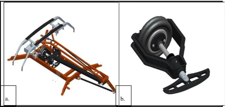
[image:6.612.112.486.374.551.2]The aim of the work was to analyse the assembly work time of the half-asymmetrical rail pantograph (see Figure 1) and the proposal to reorganize the work station and the production technology. The assembly process of the entire pantograph was recorded, and then 2 components were selected in order to perform the examination of the assembly operation time of these components. This article presents one assembly element - the Drive-Module Assembly (DMA). A comparative analysis of assembly operations according to the Methods Time Measurement and Timing was assumed. The scope of the tests covered the period from September 1 to November 15 of the same year.
Figure 1. a. Railway pantograph, b. Drive-Module Assembly (DMA).
Based on the recorded video, all activities performed by one employee during the assembly processes of the pantograph were registered. On the basis of the observations made in the previous period, during the recording, the employee performed work under normal conditions of the work environment and intensity of effort, and he had the appropriate level of the experience and skill in performing activities and worked according to the established method, according to literature recommendations [9]. On the basis of the film, the measured real time
was recorded. All major materials and components were weighed. The distance covered by employee and the dimensions of the work stations were measured. Then, the film was repeatedly played; and based on the MTM method, according to the norms of this methodology, all elementary movements made by the employee were described and the appropriate codes and times were assigned in the TMU unit to them. Later on, the results were compared with the time of the timing method. Next, when analysing the obtained results, it was proposed to reorganize the workstation and assembly method. Then, for the reorganized work station and the method of assembly, the elementary movements and times were described and codes assigned.
RESEARCH RESULTS
Tis subsection will present the values of time during performed DMA assembly operations according to norms of MTM elementary time, before proposed reorganization of working station and production technology as well as theoretical times that could be obtained after introducing changes in the organization of the assembly station and technology. The values given are values for covering movements, and covered movements were also included in the analysis but were omitted in the record, due to their shorter duration.
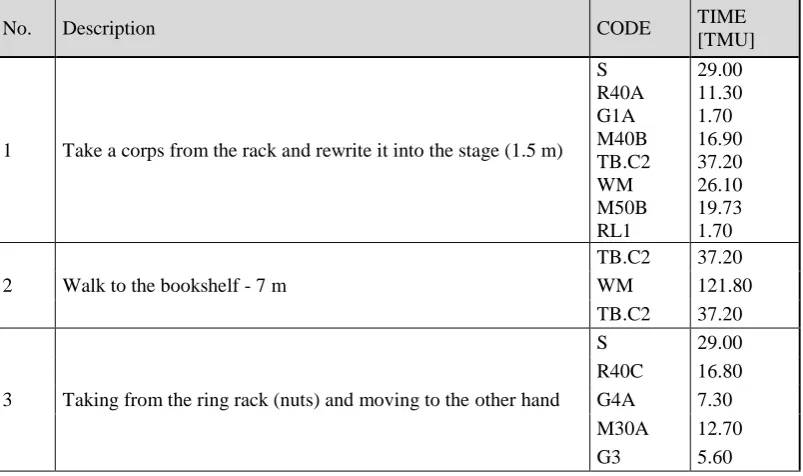
[image:7.612.98.500.441.679.2]During the analysis, the assembly process was divided into 153 operations (see Table I).
TABLE I. PART OF THE TIME MEASUREMENT RESULTS OF THE ASSEMBLY OPERATIONS OF DMA ACCORDING TO THE MTM.
No. Description CODE TIME
[TMU]
1 Take a corps from the rack and rewrite it into the stage (1.5 m) S R40A G1A M40B TB.C2 WM M50B RL1 29.00 11.30 1.70 16.90 37.20 26.10 19.73 1.70
2 Walk to the bookshelf - 7 m
TB.C2 37.20 WM 121.80 TB.C2 37.20
3 Taking from the ring rack (nuts) and moving to the other hand
S 29.00
…
124 Taking the nut from the table - M16 A2
R20A 7.80 G1B 3.50 G2 5.60 M30A 12.70 M30C 15.10 P1SSE 18.20 …
153 Putting the subassembly down to the intermediate position M60C 29.46 RL1 1.70
SUM
[TMU] 26483.33
[s] 953.40
[min] 15.89
Real time assembly (according to timing) [min] 16.02
Difference [min]
0.13
[%] 0.81
The chart below (see Figure 2) presents a Pareto Diagram showing the percentage of movements in relation to the total value of time expressed in minutes. All elementary movements according to MTM are listed: motions of the
upper limbs from Group 1, concise movements from Group 3 as the body, leg,
[image:8.612.95.500.83.326.2]and eye movements. The summary also contains the total time of movements from all three groups of elementary movements.
Figure 2. Pareto Diagram with the participation of individual movements in the DMA assembly process.
5.91
4.65
2.01
1.10
0.75 0.56 0.45
0.26 0.09 0.06 0.04
0% 20% 40% 60% 80% 100% 120% 0.00 1.00 2.00 3.00 4.00 5.00 6.00 7.00 TIME [min]
1 2 3 4 5 6 7 8 9 10 11
Movements from Group 3 represents walk, steps, and rotating the corps
movements; therefore, those movements are combined and grouped into one
collection named walking, and then referred to the total value of elementary
movements times from Group 3.
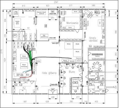
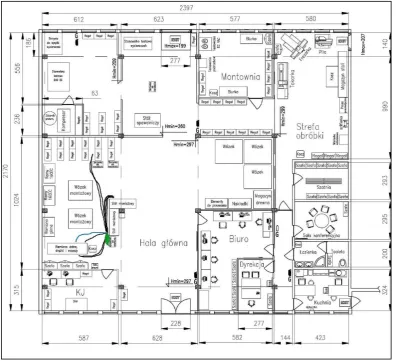
[image:9.612.98.487.251.604.2]To illustrate the distance the employee performs during the DMA assembly process, a Spaghetti Diagram (see Figure 3) was made on the basis of the recorded film. All of the paths of the road that the employee overcomes in order to collect material (black line) and tools (green line and red line) have been marked on the layout of the production hall.
During the analysis of elementary movements, it was noted that the employee used the material to cover the path 8 times between the assembly table and the shelves, 3 times the path between the shelves, and 5 times the path between the assembly table and the tool trolley.
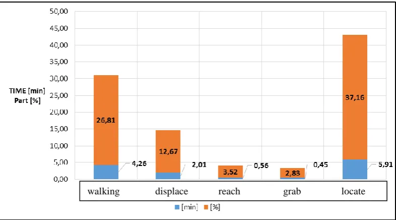
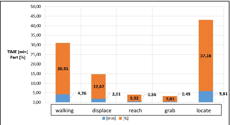
Figure 4 shows the temporal and percentage share of these elementary movements for which a change in the time value was expected after the reorganization. By changing the organization of the work station, placing all the materials needed on the stage, it was expected to reduce the time of elementary
movements, e.g., reach, grab, and move, because the movements were replaced
while retrieving materials from storage racks and again from the assembly table during assembly operations, making them only once when reaching, picking up, and moving the material from the cuvette set on the stage. By changing the order of movements, and the technologies of producing some materials, it was expected
[image:10.612.103.496.305.523.2]to obtain measurable results also in the case of movement to locate.
Figure 4.The participation of the most important movements in the DMA assembly process.
In order to shorten the operation time, after the analysis of the current working time, changes in the organization of the workplace and technology were proposed. It was assumed that each manufactured semi-finished product will have its own workstation, specially adapted to its production. All materials, lying in the litter boxes on the storage racks, should be placed on the production table in the coverage area, in front of the employee, in the litter boxes stacked in a row. All painted elements should be placed on the shelf behind the assembly table, in the place of the storage of painted lower arms, rods, and drives. Painted elements
should be protected against priming and painting, including protecting the holes from preparations getting inside. All elements that must be treated in the current process should be made according to the desired dimensions. They can also be machined at a different stage of production than assembly, so that the employee has a ready-made element for assembly.
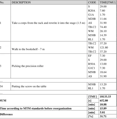
[image:11.612.100.500.232.641.2]After the changes were made, the working time analysis was performed again. During the analysis, the assembly process was divided into 138 operations (see Table II).
TABLE II. PART OF THE TIME MEASUREMENT RESULTS OF THE ASSEMBLY OPERATIONS OF DMA ACCORDING TO THE MTM AFTER REORGANIZATION.
No. DESCRIPTION CODE TIME[TMU]
1 Take a corps from the rack and rewrite it into the stage (1.5 m)
S 29.00 R20A 7.80 G1A 1.70 M20B 11.66 AS 31.90 TB.C2 74.40 WM 26.10 M30B 14.39 RL1 1.70
2
Walk to the bookshelf - 7 m
TB.C2 37.20 WM 121.80 TB.C2 37.20
3 Picking the precision roller
EF 7.30 S 29.00 R50A 13.00 G1C1 7.30 M50B 18.64 AS 31.90 …
34 Putting the screw on the table M30B 13.20 RL1 1.70 …
SUM
[TMU] 18133.33
[s] 652.80
[min] 10.88
Time according to MTM standards before reorganization [min] 15.89
Difference [min] 5.01
The total results given in the table are the values of time that can be obtained by running the manufacturing process according to the proposed changes. Then all of the operations were rewritten, the elementary movements were described, and the times were assigned to them. Times remaining in the process of non-normative activities were recorded. Results of times of individual elementary movements from Group 1, the total time of movements from Groups 2 and 3
collected in group named movements of the body, legs, and eyes and the time of
non-normative activities after reorganization.
From the Pareto Diagram (see Figure 5) prepared for new time values, it is
clear that still about 80% of the total assembly time consists of movements to
[image:12.612.100.486.291.518.2]locate, displace and move the body, legs, and eyes. This is due to the fact that the greatest time reduction was obtained for the set of movements from Groups 2 and 3.
Figure 5.Pareto Diagram with the participation of individual movements in the DMA assembly after reorganization.
After reorganization (orange line), the elementary movements of Group 1 represent 86.91% compared to 63.76% before the reorganization (blue line) (see Figure 6).
1 2 3 4 5 6 7 8 9 10 11
Figure 6. Comparison of the percentage share of individual groups of elementary movements before and after the reorganization.
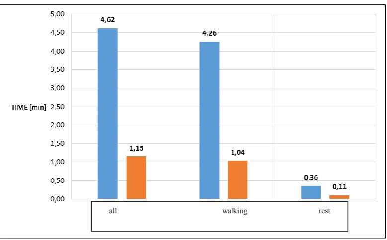
The graph in Figure 7 shows the share of movements from the walking group and the rest of elementary movements from Group 3 in relation to the total time of Group 3 movements after the process was reorganized.
Figure 7. Comparison of the percentage share of individual groups of elementary movements before after reorganization.
63.76
0.19
29.10 86.91
0.28
10.57
0.00 5.00 10.00 15.00 20.00 25.00 30.00 35.00 40.00 45.00 50.00 55.00 60.00 65.00 70.00 75.00 80.00 85.00 90.00 95.00
grupa 1 grupa 2 grupa 3
[%]
wartości obecne [%] wartości po reorganizacji [%]
all walking rest
[image:13.612.103.493.411.653.2]A new Spaghetti diagram (see Figure 8) showing the worker's movement during the assembly of the DMA after the changes was made – collecting material (black) and collecting tools (green).
Figure 9 presents a comparison of the percentage share of the most important elementary movements for which the value of time was expected to change. The chart contains the values of the times of the given movements before and after the reorganization.
Figure9. Comparison of the percentage share of the most important movements in the DMA assembly process before and after reorganization
Looking at this movement from the perspective of their percentage participation in the process after the reorganization, one can notice some larger
changes in these values. Traffic share of relocate increased by 6.75%, reach by
1.83%, grab by 5.98%, and locate by 18.14%, among others, thanks to the
reduction of the movement department, walk, side steps, and rotate the body with
a total value of 16.49%.
DISCUSSION AND CONCLUSION
When analysing all obtained results, one can come to the conclusion that, for each subassembly assembled in the production process, the railway pantograph should create separate work stations adapted to the production of only one semi-product. Time measurements made it possible to identify unnecessary operations that generated unnecessary time consumption. Knowing the course of each of these assembly processes, it was possible to modify the organization of the workstation so as to minimize the process time.
[image:15.612.101.494.167.381.2]The greatest reduction of time was achieved by transferring most of the materials needed for production from the storage rack to the cuvettes placed on the stage. First of all, it allowed reducing the time of elementary movements from Group 3. The employee did not have to move so much around the hall to collect materials during assembly operations. Most of them were at hand or near the work station, or on a shelf with painted elements, to which he was 3 meters away. The transfer of tools needed for assembly from a trolley located at the storage racks to one standing trolley on the right side of the stage also contributed to reducing the number of elementary movements from Group 3.
The assembly process was reduced by the time of movements from Group 3 by 3.47 minutes. Analysis of working time according to MTM also allowed us to identify activities performed during assembly, for which it was not possible to use it. These were activities related to the removal of materials and operations of applying glue to some combined elements. It is not advisable in the assembly processes that the worker would have to carry out a removal treatment. In the case of DMA it was only grinding the inner surface of the body sleeve to remove the layer of varnish and primer used during priming, thus to achieve the inner diameter of the sleeve allowing the placement of bearings within. These operations should be eliminated by securing the holes of painted elements before priming and painting with journals, and machining should be performed before the assembly operations, or it should be commissioned to another company on the basis of cooperation. It is possible to consider the option of purchasing rollers machined so that it can be easily place bearings on them without having to do any additional machining. Before the changes, the elementary movements of Group 1, i.e. the movements of the upper limbs, constituted only 63.76%. The application of changes was reflected in the values of individual elementary movements, which is best seen in the percentage of movements from Groups 1, 2, and 3 - 86.91%, and their share was increased by 23.15%.
It took about 48 man-hours to investigate and analyse the movements performed during the operation. Taking into account the sum of all assembly operations (before and after the reorganization amounting to 54.32 minutes), it turns out that it took 53.02 man-days to analyse the one minute assembly operation. This is consistent with data given in the literature [10]. However, despite such a long time needed to perform the analysis, choosing this method enabled the distribution of activities performed on elementary movements, the change of which was the basis for the reorganization of the work station and production technology.
In summary, the analysis gave the opportunity to optimize. However, from the perspective of this type of production, such analysis is very time-consuming. It is confirmed that MTM is best for mass production. In the future, for this company, it is more appropriate to use MTM-2 or MTM-3 with a greater degree of merge of movements.
REFERENCES
1. Jasiński, Z.1999. Zarządzanie pracą – organizowanie, planowanie, motywowanie, kontrola. Warszawa: Agencja Wydawnicza „Placet”.
2. Drążkiewicz, A. 1979. Metoda normatywów elementarnych MTM-1. Warszawa: Wydawnictwa Naukowo – Techniczne.
3. Di Gironimo G., Di Martino C., Lanzotti A., Marzano A., and Russo G. 2012. “Improving MTM-UAS to predetermine automotive maintenance times”, International Journal on Interactive Design and Manufacturing, 6(4):265-273.
4. Mreła, H. 1975. Technika organizowania pracy. Warszawa: Wiedza Powszechna.
5. Żurek, J., O. Ciszak, R. Cieślak, and M. Suszyński. 2007. „Badania czasu pracy w procesie montażu”, Technologia i Automatyzacja Montażu, 2-3:30-35.
6. Mreła, H.1979. Metody badania pracy. Warszawa: Państwowe Wydawnictwo Ekonomiczne. 7. Żurek, J., O. Ciszak, R. Cieślak, and M. Suszyński. 2006. „Metody badania czasu pracy w
procesach montażu”, Technologia i Automatyzacja Montażu 3:43-46.
8. Cakmakci, M. and M.K. Karasu. 2007. „Set-up time reduction process and integrated predetermined time system MTM-UAS: A study of application in a large size company of automobile industry”, International Journal of Advanced Manufacturing Technology, 33(3-4):334-344.
9. Strzelecki, T. 1983. Podstawy organizacji i normowania pracy. Warszawa: Państwowe Wydawnictwo Ekonomiczne.
10. Wołk, R. 1960. Techniczne normowanie czasów obróbki, cz. I – Podstawowe zasady normowania. Warszawa: Państwowe Wydawnictwa Techniczne.
11. Morlock, F., Kreggenfeld N., Louw L., Kreimeier D., and Kuhlenkötter B. 2017. “Teaching Methods-Time Measurement (MTM) for Workplace Design in Learning Factories”, Procedia Manufacturing, 9, 369-375.
12. Łyp-Wrońska, K. 2016. “World Class Manufacturing methodology as an example of problems solution in Quality Management System”, Key Engineering Materials, 682:342-349.
14. Choodoung, S. and U. Smutkupt. 2012. “Analysis Design for Assembly by MTM-2 (Methods Time Measurement-2) for Wood Joints in furniture”, Advanced Materials Research, 566:394-398.
15. Renu, R. at al, 2013, “Automated Navigation of Method Time Measurement Tables for Automotive Assembly Line Planning”, ASME 2013 International Design Engineering Technical Conferences and Computers and Information in Engineering Conference. Volume 4: 18th Design for Manufacturing and the Life Cycle Conference; 2013 ASME/IEEE International Conference on Mechatronic and Embedded Systems and Applications, Portland, Oregon, USA, August 4–7, 2013.