2018 International Conference on Computer, Communications and Mechatronics Engineering (CCME 2018) ISBN: 978-1-60595-611-4
Design and Testing Method of Geometric Tolerances for
Deep Stepped Hole
Chang-an HU
*National Institute of Measurement and Testing Technology, Chengdu, 610021, China
*Corresponding author
Keywords: Geometric tolerances, Deep stepped hole, Machining, Coaxiality error.
Abstract. Effective process checking tool is an important means to control the first pass rate and machining quality of large-size and high-precision parts in precision manufacturing. Its testing method and testing precision directly affect the reliability of precision manufacturing process system. Aiming at the problems of high machining and assembling precision, many machining parts and difficult detection of large-scale parts, the precision detection method for complex parts with high precision and deep step hole design characteristics was studied. Based on the drilling-expanding-rough boring-fine boring process, the control factors of coaxiality error and the machining errors caused by the weight of larger cutting tools in high-speed machining process are analyzed. The position relationship of the measured coaxial stepped holes is studied. A special measuring tool is designed to measure the coaxial machining error quickly and accurately. The corresponding process measuring method is given. The method is applied to the precise manufacturing process of this feature. The testing results are verified by a three-coordinate measuring instrument. The comparative study shows that the tool can effectively measure the coaxiality error of two holes in long distance, and visually display the size and position of the coaxiality error of two holes, effectively improving the efficiency of coaxiality error detection with two holes in long distance.
Introduction
Coaxality is a common location tolerance in geometric tolerances for machine parts inspection. According to the national standards, coaxiality refers to the different degrees of the axis of the tested parts to the reference axis. Various spindles and testing instruments can be used to test coaxiality.
Coaxiality is a position parameter which is difficult to measure. Large-scale boring and milling machines are generally used to process the structural features of large size and large hole spacing[1]. However, the diameter compensation is also needed when machining the inner and outer circles of the shafts with high precision[2]. Especially in the structure of large parts with small space where the coaxial holes are located and mass-produced. The accuracy and efficiency of two-hole coaxiality measurement is an important factor affecting the quality and efficiency of product production. Therefore, the necessary prerequisite for accurate machining of inner and outer circles of parts with deep and long stepped holes is to inspect them in the process of machining, and choose the corresponding compensation according to the measurement results, so as to adjust the follow-up processing. Because of the displacement gap of the large machine tool itself which compensates the weight of the parts, the measurement and compensation of the machining process is especially important for the precision machining process system of the large-size and high-precision conical shaft parts[3]. Therefore, the design of the measuring tool for form and position tolerance in the machining process around the validity and efficiency is widely used by engineers and technicians. General concern.
detection, the detection accuracy is very high, can reach 0.001 mm. It can be seen from this that the machine vision technology can meet the requirements of high precision inspection for mechanical parts. The traditional way to detect the line width is to detect two edges separately and calculate the linewidth. The traditional methods of subpixel line width detection include interpolation, fitting, etc. But these methods have some problems, such as low accuracy, or large amount of calculation, so it is difficult to meet the requirements of real-time online detection. Legendre orthogonal moments have been widely used because of the least redundancy of information and simple inverse transformation. Ghosal et al. [6] proposed a sub-pixel ideal step edge detection model based on orthogonal moments, and has been widely used. Muhammad et al. [7, 8] proposed a subpixel linewidth measurement method of Legendre orthogonal moments to measure the linewidth of 100 m standard granules in ampoules. Literature [9] discloses a kind of taper measuring device, which greatly improves the accuracy of measuring taper and reduces the measuring error by adding a positioning sleeve in the measuring device. However, because the technical scheme has a fixed measuring base plate, the measuring device can only be used in the final inspection of products and cannot be used as a process measuring tool. However, this method does not Accurate values of taper deviation can be obtained, which cannot be further measured through the feedback processing, and cannot play a role in compensating and guiding the processing. Develop a testing device which can be used in taper machining process, and get accurate testing results, can effectively guide the processing process, and improve processing efficiency.
Based on the above situation, according to the calculating formula of taper and roundness tolerance, this paper designs a taper measuring tool which can be conveniently applied to the machining process of large conical shaft parts. By modifying the measuring tool, the deviation value of actual taper and theoretical taper and the position of machining error can be accurately obtained, which can further guide the follow-up machining and improve the large-scale and high-precision machining. The forming rate and machining accuracy of the taper shaft parts can improve the production efficiency of high-precision products.
Sources of Problems
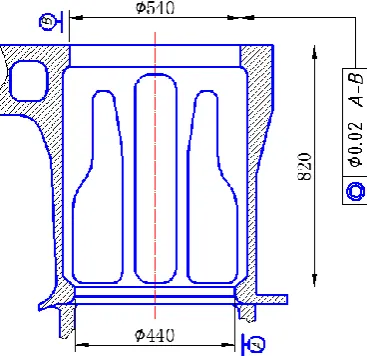
[image:2.595.205.389.527.705.2]The above situation is not uncommon in the manufacturing industry, just as the cylinder bore on the block of a large diesel engine, because of the installation of the cylinder liner, so the cylinder bore on the block is designed to be the upper and lower two ladder holes, and the axial distance between the two is larger, the coaxiality design index is 0.02, as shown in Figure 1.
Figure 1. Design requirements for coaxiality of stepped holes with large spacing on a part.
holes is small, but also not in a plane. In this case to achieve rapid measurement between processes is indeed a difficult problem. Therefore, the accuracy and efficiency of the gauge must be taken into consideration in its manufacturing process.
Design Principles of Fixture
In the appendix (1) to the national standard for shape and position tolerance, several coaxiality error detection schemes are recommended, one of which is a mechanical measuring tool scheme as shown in Figure 2. As can be seen from the diagram, the solid spindle at the left end of the measuring tool is inserted into a hole in the workpiece when it is in use, and a measuring lever is set at the right end of the measuring tool. The two ends of the lever are the probe contacting the hole under test and the anvil contacting a thousand (hundred) meters respectively. When the mandrel rotates a circle, a cross section of the hole is measured, which can be measured on one or more sections. The maximum difference between the maximum and the minimum readings of a micrometer (assuming several sections are measured) is the coaxiality error of two holes.
[image:3.595.78.517.281.380.2]
a) Coaxiality error b) Existing detection methods
Figure 2. Design requirements for coaxiality of stepped holes with large spacing on a part.
In the national standard, the coaxiality tolerance of the axis is defined as "the tolerance zone is the area within a cylindrical surface with a diameter of and the axis of the cylindrical surface is coaxial with the reference axis". It has the following three control elements: (1) the establishment of the reference axis; (2) the establishment of the axis of the object under test; (3) considering the actual work or assembly requirements for flexibility.
However, the existing universal testing tools can only be limited to the measurement of the shape and angle of the block, but cannot achieve a rapid and accurate measurement of coaxiality size of the upper and lower cylinder holes of the internal combustion engine block. If the upper and lower cylinder holes do not meet the predetermined standards, the engine block cannot operate reliably after assembly, and the subsequent correction of the hole position often occurs. A great deal of time is needed, which is an important factor affecting the overall processing efficiency and quality.
Design of Coaxality Gauge
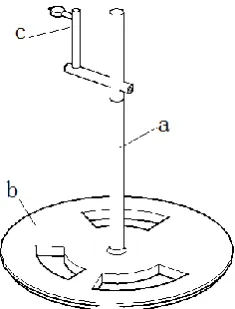
Figure 3. Coaxial measuring tool based on taper positioning principle.
The checking device comprises a checking concrete (a), one end of the checking concrete (a) is fixedly connected with a contact ring (b) through a bolt, and the other end is fixedly supported by a locking nut (c). The lower positioning plate is installed in one hole of the stepped hole, and the other is replaced by a dial. When the lower end plate rotates in one of the cylinder holes, the coaxiality error of the two cylinder holes can be quickly and accurately obtained by changing the dial pointer.
Measuring Method for Concentricity of Stepped Holes
As shown in Figure 1, the coaxality special checking tool includes a checking tool body, a contact ring and a bracket. In the structure diagram of the measuring tool, the lower structure is a contact ring, which is used to contact with one of the cylinder holes in the testing process. The middle structure is the measuring tool body. The two are connected and fixed together by threads, and the support frame is fixed at the upper end of the measuring tool body, which is used to fix dial gauge or scratch needle in the measuring process. When the coaxiality of the two cylinder holes of the engine block needs to be detected, the contact ring of the detection device is connected with one of the cylinder holes of the engine, the percentage is installed on the support frame, the dial contact needle is pressed with the other cylinder hole, the dial head reading is adjusted to a certain value, and then the dial contact ring is rotated so that the dial contact head is in the cylinder. The value is the coaxiality deviation of two cylinder holes. On the other hand, when the needle is mounted on the support frame, the same operation can be done by turning the needle one circle to draw the contour line on the inner surface of the hole. The specific measurement steps are as follows:
Preparation before Measurement:
The surface of the measuring tool and the part under test is cleaned to prevent foreign bodies from entering the contact surface, which results in the failure of the measuring tool to contact the surface of the part under test precisely and the accuracy of the measuring data.
Loading Card:
[image:5.595.194.402.447.583.2]Install the contact disc of the measuring tool in the small hole of the two step holes and ensure that it is fully in contact with the hole under test. Then adjust the dial gauge to the same height as the other hole. Install the dial gauge on the support. The dial gauge and the inner surface of the hole are in contact to ensure that the dial gauge pointer rotates one time and readjust the dial gauge. The zero point, as the zero reference point of the coaxial degree, is installed. The fixed profile and the stepped hole state are shown in Figure 4.
Figure 4. Assembly of coaxial gauges.
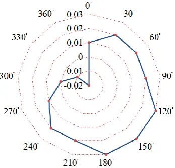
Coaxiality Measurement:
Figure 5. Coaxiality error curve obtained by measurement.
Conclusion
Equations Aiming at the problems of complex process, narrow space and inaccurate detection of coaxiality of long-distance stepped holes, a special testing tool for coaxiality was designed. The utility model relates to a quick measuring mechanism for processing the internal combustion engine block. The detection mechanism mainly includes the detection of specific, specific one end of the fixed contact ring, the other end is equipped with adjustable height of the support frame, can achieve the internal combustion engine block up and down cylinder bore coaxiality size of rapid and accurate measurement. The detection device can not only install a scratch needle for scratching measurement, but also install a dial meter to display specific coaxiality values, which is convenient and practical.
References
[1] Cai Ming. Research on process oriented tolerance design system based on CAD integration[A]. Chinese society of Mechanical Engineering .Proceedings of the 4~(th) International Conference on Frontiers of Design and Manufacturing[C]. Chinese society of Mechanical Engineering, 2000:6.
[2] Zhang Rui-sha, Kang Ruisheng, Cui Qing-chun. A new method of machining longer taper [J]. Machinery Design & Manufacture, 2006(03): 91-92.
[3] Wang Cui-biao, Liu Hong-wei, Gaowei. Application of profile modeling to turning parts of taper shaft on ordinary lathe [J]. Machinery Design & Manufacture, 2007(06): 109-110.
[4] Zhao Xingren. Design of new vertical coaxial cone inspection tool [J]. Tool technology, 2018, 52 (01): 141-142.
[5] H. Zenkouar, A. Nachit. Images compression using moments method of orthogonal polynomials[J]. Materials Science & Engineering B. 1997 (3).
[6] Nikolay Nazaryan, Claudio Campana, Saeid Moslehpour, Devdas Shetty. Application of a He3Ne infrared laser source for detection of geometrical dimensions of cracks and scratches on finished surfaces of metals[J]. Optics and Lasers in Engineering, 2013 (12).
[7] Muhammad Azmi Ayub,Azmi B. Mohamed,Abdul Halim Esa. In-line Inspection of Roundness Using Machine Vision[J]. Procedia Technology, 2014.