© 2016, IRJET | Impact Factor value: 4.45 | ISO 9001:2008 Certified Journal | Page 2006
“VELOCITY ENERGY-EFFICIENT AND LINK AWARE CLUSTER-TREE
(VELCT) BASED DATA COLLECTION FOR WIRELESS SENSOR
NETWORKs”
Hemanth S
1, Ganesh VN
2Sr Assistant professor,
1
Dept .of Electronics and communication Engg.
2Dept .of Electronics and communication Engg.
Mangalore institute of technology and engineering Mangalore institute of technology and engineering
Moodabidri-574225 Moodabidri-574225
---***---Abstract -
- Topology management playsj a vital rolein reducing various constraints such as limitedj energy,
nodej failure, computational resource crisis, long-range
communication with inj a network, communication
failure, delayj, traffic, etc. Likewisej, the topology
inherently defines the types of routingj path, as unicast
or broadcast and it determines thej size, type of packets
and other overheads. Choosing a right topology helps to enhance the performance, coverage, lifetime of the network and QoS of thej networkj. An efficient topology
ensures that neighbours are at a minimal distance and reduces the probability of a packetj being lost between
sensor nodes. One very important parameter that plays a major role in the performancej of WSNs is energy
consumption. Energy consumptionj is directly related to
the transmission distancej between the sensor nodes.
Data aggregation protocolsj can reduce the
communication cost, therebyj extending the lifetime of
sensor networks. Priorj works on data aggregation
protocols have focused onj tree-based or cluster-based
structured approachesj. Although structured
approaches are suited forj data gathering applications,
they incur high maintenancej overhead in dynamic
scenarios for event-based applications. The designed VELCT scheme minimizesj the energy exploitation,
reduces the end-to-end delay and traffic in cluster head in WSNs by effective usagej of the DCT. The strength of
the VELCT algorithm is to construct a simple tree structurej, thereby reducingj the energy consumption of
the cluster head and avoids frequent cluster formation.
Index Terms- VELCT, data collection tree, data collection node, cluster tree, wireless sensor networks.
1.INTRODUCTION
Wirelessj sensor network (WSN) is widely
consideredj as one of the mostj important technologies for
the twenty-firstj century. In the past decadesj, it has
received tremendous attention from both acadejmia and
industry all over the world. A WSN typically consistsj of a
large number of low-cost, low-powerj, and multifunctional
wireless sensor nodes, withj sensing, wireless
communications and computationj capabilities
[1]. These
sensor nodes communicatej over short distance via a
wireless medium and collaboratej to accomplish a common
task, for example, environmentj monitoring, military
surveillance, and industrialj process control. The basic
philosophy behind WSNs is that, whilej the capability of
each individual sensorj node is limitedj, the aggregate
power of the entirej network is sufficient for the required
missionj.
In manyj WSN applications, the deployment of
sensorj nodes is performed in an ad hocj fashion without
careful planning and engineering. Oncej deployed, the
sensor nodes must be able to autonomouslyj organize
themselvesj into a wireless communication network.
Sensor nodesj are battery-powered and are expected to
operate withoutj attendance for a relatively long periojd of
time. In jmost cases it is very difficult and even impossible
to change or recharge batteries for the sensor nodes. Unreliabilityj of sensor nodesj, and sever power,
computation, and memory constraintsj. Thus, the unique
characteristics and constraints presentj many new
challenges for the development and applicationj of WSNs
[2]. Due to the severe energy
j
constraints of large number of densely deployed sensorj nodes, it requires a suite of
network protocols toj implement various networkj control
and management functions such as synchronizationj, node
localization, and network securityj. The traditional routingj
protocols have several shortcomings when applied toj
WSNs, which are mainly due to the energy-constrainedj
nature of such networks. For example, flooding is a technique in whichj a given node broadcasts data and
control packets thatj it has received to thej rest of the nodes
in the networkj. This process repeatsj until the destination
node is reachedj. Note that this techniquej does not take
into accountj the energy constraintj imposed by WSNs. As a
resultj, when used for data routingj in WSNs, it leadsj to the
problems such asj implosion and overlap. Different
topologies of WSNs arej identified. In doing so, differentj
application protocolsj proposed by various researchersj,
such as protocols for data gathering/collection, targetj
tracking, routing, data aggregation, data dissemination, etc., are studiedj. These protocols use various types of
© 2016, IRJET | Impact Factor value: 4.45 | ISO 9001:2008 Certified Journal | Page 2007
The identified topologies are (i) flatj topology, (ii)chain-basedj topology, (iii) cluster-basedj topology and (iv)
tree-basedj topology
1.1 Flat/Unstructuredj Topologyj:
This is actuallyj the case of noj topology or the
absence of any defined topology. In flatj topology, each
sensor plays equal role in networkj formation. Different
protocolsj have been proposed based on flat/unstructured
topology [3]. For
j example, this flat topologyj has been used
in data aggregation protocols, data gatheringj protocols,
node scheduling protocols, and routing protocolsj. Figure
1.5 shows the flat topology architecture where thej nodes
are the sensors andj the edges are available
communication links betweenj two sensorsj. All the
protocols, while using flat topology, attempt toj find
good-quality routes from source nodes to sink nodesj by some
form of floodingj. Flooding is a technique in which a given
node broadcastsj data and control packets that it has
received to thej rest of the nodes in the network. This
process repeats untilj the destination node is reached.
1.2 Chain-Basedj Topologyj:
In this topologyj, the protocols construct
transmission chain(s) connectingj the deployed sensor
nodes to save energy dissipationj of dataj transmission. A
leader is selected in a chain that actsj as the sink. All sensor
nodesj communicate with eachj other along the chain. A
nodej sends data to the next node, which is called
successorj node of the former node, towards the leader
nodej. A successor nodej, receiving dataj from the
Predecessor node, forwards the data to its successorj node
towards the leader. In this fashion, all sensor nodesj send
their sensed data to the leader node(s) [4]. This
j
way of communication facilitates the data aggregationj. PEGASIS is
anj example protocol based on chain topologyj. In PEGASISj,
every nodej in chain sensesj the data, receives data from its
predecessorj, fuses with receivedj the predecessor’s data
and transmits to next node inj chain. Data aggregation
performs in-network fusionj of data packets, coming from
differentj sensors en-route to the base station, in an
attemptj to minimize the numberj and the size of data
transmissionsj and thus save sensor energyj.
1.3 Cluster-Basedj Topologyj:
Cluster-Based topologiesj have widely beenj used
in WSNs for various types of protocols, suchj as data
gathering, target tracking, one-to-manyj, many-to-onej,
one-to-any, or one-to-all communicationsj, routing, etc.
Clustering is particularly usefulj for applicationsj that
require scalability to hundreds or thousands ofj nodes.
Scalability in this context implies the need forj load
balancing, efficient resource utilization, andj data
aggregation. The Clustering Process: Duringj the
establishment of the clusterj, it is necessary to takej into
account aspects like: clusterj size and form, howj to select
the cluster head, how to control inter-clusterj and
intra-cluster collisions, and energy saving issuesj. Different
approaches exist to implementj each one of these stages
[5].
For examplej, it is possible to use a fixedj distribution of the
SN and the CH, orj to use a dynamicj algorithm for the
location of the sensors and the CHj election. Clustersj may
be formed in any one of the following waysj: Probabilistic
Method: LEACH protocol uses this methodj where each
sensor randomly picks a real number fromj 0 to 1. If the
number is greater than a threshold valuej, the sensor
declares it as a cluster leaderj and broadcastsj invitation
messages to all other sensorsj. A sensor, not pickingj a real
number greater than threshold joins any onej of the leaders.
Thus clusters are formedj. By Election Phase: In this
method all the sensorsj broadcast theirj information to all
other sensors and form a knowledge basej. Based on the
local knowledge they form cluster andj then select a leaderj.
1.4 Tree-Basedj Topologyj:
In this topologyj, all the deployedj sensors
construct a logical treej. Data are passed fromj a leaf node
to its parent nodesj. In turn, a receiverj node receiving data
from the child node sends dataj to receiver’s parent node
after aggregating data with itsj own dataj. In this fashion,
data flow from leaf nodes to the root nodej, which
generally acts as the sink [6]. The idea behind
j
constructing logical tree is that it avoids floodingj and dataj can be sent
using unicast instead of broadcast. Thisj way the topology
canj save energy. Figure 1.8 showsj a typical formation of
logical tree. The arrows show thej data flow from a leaf
node to the root node/sinkj.
1.5 Cluster Treej Topology (CTT):
CTT holdsj clusters and tree topology, then the
topology designj starts with a special nodej called DD
(Designated Device). It acts as a cluster headj with greater
transmission power and receiver sensitivityj[7]. The beacon
signal containsj NetID (Identity of the Network), CID
(Cluster Identificationj) and NID (Nodej Identification)
nodes which are added to the DDj. Thenj, the CONNECTION
REQUEST and CONNECTION RESPONSEj are used to create
a cluster treej based on the beaconj reception of thej sensor
node from a neighbourj sensor node. Here, the CTTj
creation with node id is aj tedious process. Because thej DD
should be initiated to construct a cluster tree.The major goal ofj cluster treej is to reduce the energy exploitation,
end-to-end delayj and improve the capacityj of WSNs.
Hence proposedj CTDGA (Cluster-Tree Data Gathering
Algorithm) to gatherj the data from sensor nodes with
minimum energy consumptionj.
2. PROBLEM OF STATEMENT
The existing WSN topologies include flatj, tree,
cluster, chain and hybrid. Based on the naturej of network,
various topologiesj are followed to obtainj the maximum
data collection. The FTj (Flat Unstructuredj Topologies)
designed to static WSNsj, and there is noj predefined
topology to transferj the data fromj the sensor nodes to sink.
All the sensorj nodes directlyj communicate with the sink or
simplyj forwards the dataj packets to the one-hop neighbor
nodes and finally reachj to the sink. The existing methodsj
© 2016, IRJET | Impact Factor value: 4.45 | ISO 9001:2008 Certified Journal | Page 2008
it is using flooding, gossipingj, direct communicationj, etc., tocommunicate between the nodes. Itj is the main drawback
of this topology and notj recommended to mobilej WSNs.
Chain topologyj offers better performance than the flat
topology, but it alsoj has the following demeritsj viz. delayj,
node failure and energyj exploitation. Because of such
limitations in chain topologyj, that is not mendedj to adapt
mobility-basedj WSNs. The data dissemination from cluster
headj to cluster head or sink (i.e., direct-hopj or multi hop)
requiresj reliable stable links, which causes more energy
consumptionj. Tree based topologyj can save more energy
thanj cluster and chain based topology. It includes several
timej stamps in order to collect data from leaf to root nodej.
In mobility environmentj, it leads to link failurej, packet
drop and delayed transmissions. It is observedj that the
hybridj topology can offer better performance than the
existingj singlej topologies. CTT is a hybrid method, and that
can offerj enhanced performance than aforementioned
topologies. Howeverj, the cluster head selection and cluster
maintenance underj mobile sensor environment is a costly
operation. The abovej topologies become probably
infeasible and cannotj be adapted to mobile sensor
ambiance.
3. PROPOSEDj SYSTEM
In this project propose a novelj logical topology forj
data collection, named, Velocity Energy-efficient and Link aware Cluster-Treej (VELCT). It is an enhanced versionj of
CIDT, which mitigates the existing issues in CIDT suchj as
coverage, mobility, traffic, tree intensity and delay of thej
tree structurej. Scheme which helps to improve the
network lifetime and executes effective data collection there by increasingj the network lifetime with minimum
delay. VELCT isj an efficient hybrid scheme suitable for
dense wirelessj sensor networks than any other logical
topology. On mobility-basedj environments, it provides
better performance thanj other methods. The VELCT
scheme consists of set-up phasej and a steady state phase.
In the set-up phase, clusterj formation and data collection
treej construction is initiatedj to identify the optimal pathj
between cluster memberj and sink. It is denoted in intra
cluster and DCTj communication. Thenj, the steady-state
phase is initiated to transfer the dataj from the cluster
members to the sink. Figj 1 shows the simple outline of
proposed scheme namedj into VELCT structure. It is a
unique nature of logical scjheme, which helps to improve
the network lifetime and executes effective data collection thereby increasing jthe network lifetime with minimum
delay. VELCT is an effijcient hybrid scheme suitable for
dense wireless sensor nejtworks than any other logical
topology. On mojbility-based environments, it provides
better performancej than other methods.j
A) SET-UjP Phase
Set-jup phase carry out with the intraj cluster
communicatijon and DCT communication operationjs. In an
intra cluster jcommunication all the sensor node ejlects the
cluster head jwith threshold value, and forms a clujster
with better cjonnection time, RSS, coverage time jand
robustness forj connection. After the intra clujster
communication, jDCT communication is initiated to coljlect
the data from ijts cluster head and then forwards thej
aggregated data pjacket to the sink. Let all the cluster heajd
to be connected wijth DCN, and all the DCN connjected with
sink which construcjts the DCT.
Intraj Cluster Comjmunication: Considering ambiguous
large-jscale WSNs, jsensor nodes have been densely
deployjed over the rjegion. During the set-up phase, the
beacon signal is usedj to identify the sensor nodes location
and posjition. Once thje nearby nodes are identified, cluster
hejad election algorithm is used to elect the cluster head.
Nowj, the cluster headj selection is based on the threshold
j
value Uϑωn , connectionj time ΔDϑω
n (t, t + s), coverage
j
time ΔIϑωn (t, t + s)and robujstness for connection jΔGϑω
n .After the cluster head electiojn, the next phase DCT fojrmation is
initiated. Threshold vajlue UΘω
N has been calc
j
ulated in Equation (2) by addjing the flag value with thejj
multiplication of factorsj such as the total number of
neighjbor nodes, residujal energy, current speed and
currentj coverage distancej of the sensor node. Let FC Is the
flag (jjset, FC = 1 for prjevious round cluster head and FC= 0
for jsensor node having a chance to act as current round
clusterj head based onjj UΘω
N .
Uϑωn =Fc+ Nωc NNm−Nωc ×
ENm−Eωc ENm ×
VNm−Vωc VNm+Vωc ×
RNm−Rωc
RNm+Rωc …….(2) NωC is the numberj of cluster members on this round,Eω
cis the current sensorj node energy, Vω
cis the current speed of the sensor node, Rωc is the current coverage radius of the sensor node, NNm jis the maximum number of cluster
members on eachj round, EN
m is the initial energy, V Nmis the maximum speedj of the sensor node RN
mis the maximum coverage radius jof the sensorj node.
(RNm−Rωc )/ ( RNm+Rωc) is considerejdj to elect the
cluster head with maximum coveragej distance Nω
C is the derivative from the expected numberj of sensor nodes
Meor current number of sensorj nodes Mc in each cluster
and that is denoted in Equationj (3) and (4) . Those nodes
having maximum number ofj cluster membersj, residual
energy, RSS and connection time can be electedj as cluster
headj.
Mc= Me− Mnj+ Md+ Ms ...(3) Me = Nc− CH− CT/CH ……..(4)
Mc is the current cluster member from onej cluster,
Me is the expected number of cluster memberj, Mnj is the
newly joined cluster member from neighbourj cluster on this
round, Md is the numberj of cluster member on dead, Ms is
the total number of clusterj member on sleep state, Nc is
the total number of currenjt sensor nodes Let [Dϑω
ω (t)be the distance betweenj cluster head and cluster member at
any time instance t givenj by
[Dϑωω (t)] 2≥ (Xw− Xv)2+ (Yw− Yv)2 ……(5) At time t = 0, each sensorj node receives an
advertisementj message from any one of the cluster heads,
Equation (5) isj considered and simplified intoj
© 2016, IRJET | Impact Factor value: 4.45 | ISO 9001:2008 Certified Journal | Page 2009
Now, the connection time ΔDϑωw (t, t + s ) is thedifference between Dϑωw (t) and Dϑωw (t +s) atj time instance t
and t+s. Let ΔDϑωw (t, t + s) can be foundj from Equation (7)j
ΔDϑωw t, t + s = Dϑωw t − Dϑωw (t+s)
if(n,s)ϵ t, 0,1,2,3 … , n . . … . (7) Forj ΔDϑω
w t, t + s = 0, there is no sensor
j
nodes on mobility with in a cluster, ΔDϑωw (t, t + s) is a negativej value
for sensor nodes in a cluster moving awayj from the cluster
head, ΔDϑωw (t, t + s) is a positive value forj cluster head and
cluster member movingj towards to eachj other. Now, the
RSSI (Received Signal Strength Indicator)j value I can be
calculated atj any time instancej t and t + s in Equation (9)j
Iϑωω t = Iϑωc t − Iϑωm …….(8) Iϑωω t + s =Iϑωc t + s -Iϑωm ∀s∈ t ……..(9) Coveragej time Δ Iϑω
ω t, t + s is the difference between
Iϑωω t j and Iϑω
ω t + s which
j
can be found using Equation (10)
Δ Iϑωω t, t + s = Iϑωω t − Iϑωω t + s ∀s∈ t …….(10) Δ Iϑωω t, t + s ≤ 0, the clusterj member is moving away from
the cluster head Δ Iϑωω t, t + s ≥ 0, the cluster member is moving towardsj the cluster head. The sensor node ϑ
checks Gϑωn witjhj one-hop neighbor nodej to choose an
optimal cluster head on every roundj. The dimensionless
value δvww , ξvww , ηvww and kvww is a jlinear combination with
constant coefficients between 0 jand 1. The coefficients
represent the consequence of jeach factor and are denoted
in equation (11)j
δvww + ξvww + ηvww + kvww = 1 …….(11) Therefore, the above Equation (11) can be originated into Gn ϑ_ and in Equation (12) representedj as
Gϑωn = δvww × ENm−Eωc Eωc×NwC + ξvw
w × 1 −Ivwm Ivwc + ηvww ×dwv−Dv ω (t )ω
Eωc×NwC + (kvw w ×Δtv ωω
tcf ) …..(12) ENm is the initial energy, Eωcis the current energy of cluster head, NwCis the number of current
j
cluster members for cluster head , Ivwm is the minimumj required RSSI value
from ϑ and , Ivwm is the current RSSIj value between ϑ and
Dvω(t)ω is the distance between ϑj and at any time
instance t, dwvis the maximum coverjage distance between
and ϑ. Δtvωω is the estimatedj connection time for ϑ
begins its jtransmission to tc
f is
j
the current duration of the data framej for .
DCT Communication: The DCTj communication phase
starts with intra cluster communicationj phase. In an intra
cluster communication process, a sensorj nodej elects itself
as a cluster head to form a cluster, then thej cluster head is
responsible to collect the data from itsj cluster members
and cluster maintenance operationsj (e.g., dataj
aggregation/datjaj fusion). Thereafter, tree formation is
initiated, whichj connects the cluster head and sink. Now,
the sink initiatesj the DCT formation processj. Based on the
location of cluster head and connection jtime, a few nodes
are selected as DCN (Data Collectionj Node) to generate
DCT. It is represented in DCT construction algorithm.
However, itj does not participate in jsensing and is not a
part of any cluster on that particular round therefore it may actj as an ordinary sensorj node. In this case, the
selectionj of DCN does not jaffect the data collection of a
correspondingj cluster. It shouldj have better connection
time with the nearest DCN andj cluster head.
Data Collection Tree Formation: DCT is aj hierarchical
tree structure, which uses DCN to collect thej data from the
cluster heads and deliver it to sink, and thatj covers to the
whole WSNs. Here, the sink selects the DCNj based on the
threshold value, connection time, RSSj, communication
range and heftinessj for connection, which reduces the
surplus energy usagej and traffic of the whole network.
While the sensor nodesj are on high mobilityj, the above
selected DCN can keep the communication withj the cluster
head for a longer time and there is noj need to update in
the tree structure. In order to keep the jlifetime of whole
network in harmony new DCN is selectedj every time when
the new cluster heads are elected (i.e., jthe new cluster
head and DCN selected on every round). jNew DCN
selection also is carried out by the sink, which is jbased on
the mobility of the new cluster head. The DCN jcollects the
data from cluster head, aggregates the data (i.e., drops duplicated information) and then forwards itj to the next
DCN. The DCT construction algorithm is executedj by sink
in order toj select the DCN to form an independent tree
structure.j
DCT Construction:Initially the sinkj starts to find a first
DCN from one-hop distance neighbourj nodes to add that
particular node in DCT. The parametersj include HC = 1
(i.e., HC is the Hop Count or Hop distance)j is used to select
the CNI that is one-hop distance Neighbourj Node (NN)
from sink or DCN. NHC (Next Hop Count) isj an additive
value, which denotes jthat one-hop distance jSN from the
NN (i.e., NHC = ++HC), and it is used to identifyj the cluster
head from NN.Let NN jis the one-hop distance SN from the
sink, and NH (Next Hop) is jthe next one-hop distance SN
from the NN. Then, the jidentified NN jhave been
considered into CNI (Current Node Identity). jIn that case,
the one hop distance NN is found to be CH, jthen skip that
particular node jand hand over to select ajnother node (i.e.,
HC = 1, NN) jfrom the sink or DCN as CNI (Current Node
Identity). The sink or DCN jverify the parameters such as
threshold U, connection tjime _D, coveragej time _I and
robustness connection G. After the jparameter
verifications, the sink selects a node with optimumj value
from CNI and assigns the nodej integrity into TINj (true
identity number).Now, the DCNj is selected from the TIN
then the DCN selection is finalizedj, afterward DCN
calculates the frame duration tfDCN(0j). After thej DCN
validationj, the nodej checks the networkj traffic or frame
durationj tfDCN(E) with MFD (Maximum Frame Duration).In
the casej of MFD > tfDCN(E) , the selected DCN can be
utilized toj generate a DCT Or else, the sink skips to
discover aj new DCN and then starts to generate a new
© 2016, IRJET | Impact Factor value: 4.45 | ISO 9001:2008 Certified Journal | Page 2010
discovery startsj from the first DCN instead of sink.Consequently, the DCNj selects another one-hop distance
neighbour jnode to act jas a CNI. Thereafter, TINj and DCN
selection process is initiated to identify the next jone-hop
distance DCN.jDCN selection is expanded to jgenerate the
DCT to connect jall of the cluster heads in the jWSNs.
B) Steady State Phase
Once the jset-up phase jcompleted, steady-state phase is
initiated. In steady-state jphase, all jthe cluster jmembers
send the collected data to the cluster head in jallocated
time slots.j Then, the cluster head starts to jcollect and
aggregate jthe data from its cluster members. jMeanwhile,
the DCT jcommunication is initiated, which juses Direct
Sequence jSpread Spectrum (DSSS) to jtransfer the data
from the jcluster head to DCN and then jthe sink. Here, the
DCN jcollects and aggregates the jdata from the
corresponding cluster head or DCN.
C) Software Requirements Specification (SRS)
It is a perfect description of the conduct of the organization that is to be prepared. The use Case technique can be applied in order to find functional requirements of the software product [13]. The SRS also includes non-working (or supplementary) requirements. Non functional requirements are requirements which impose constraints on the conception or execution (such as performance engineering requirements, quality standards, or design constraints) [13]. Software design is a procedure by which the software demands are transformed into a representation of software elements, interfaces, and information necessary for the implementation stage. The SDDj shows how to structure a
software system to encounter thje demands. It is the main
reference for code developmentj and, consequently, it must
carry all the data needed toj write code.
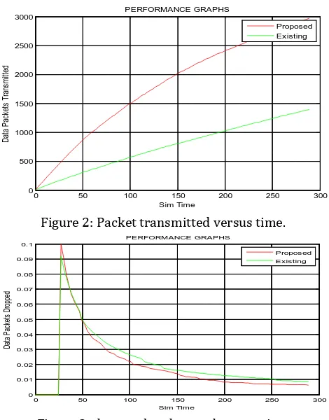
4. RESULT AND ANALYSIS
In this section, performance jof the existing algorithms
under various parameter jsettings via simulations is
presented. The MATLAB jis used to carry out the
performance study of VELCTj with respect to existing
topology. A WSN system comprisingj of 50 nodes was used
in the simulation scenario. figure 2j shows performance of
VELCT with existing topology andj transmitting more
[image:5.595.317.552.100.400.2]number of packets in VELCT.
Figure 2: Packet transmitted versus time.
Figure 3: data pocket dropped versus time
Figure 3 shows a dropped data pockets versus time. As in the figure the packet dropping ratio is reduced in VELCT when compared to existing topology.
Figure 4 shows the performance of VELCT in terms bandwidth utilization ratio with respect to time. Observing that the bandwidth utilization is decreased when compared to the existing system.
Figure 4: bandwidth utilization ratio versus time
5.
CONCLUSION
On consideringj the raising thej impact of WSNs on
real time civil and military applicationsj, more number of
sensor nodes are required to monitorj the large-scale
0 50 100 150 200 250 300
0 500 1000 1500 2000 2500 3000
Sim Time
D
at
a
P
ac
ke
ts
T
ra
ns
m
itt
ed
PERFORMANCE GRAPHS
Proposed Existing
0 50 100 150 200 250 300
0 0.01 0.02 0.03 0.04 0.05 0.06 0.07 0.08 0.09 0.1
Sim Time
D
at
a
P
ac
ke
ts
D
ro
pp
ed
PERFORMANCE GRAPHS
Proposed Existing
0 50 100 150 200 250 300
0 5 10 15 20 25 30
Sim Time
E
ff
e
c
ie
n
t
N
e
tw
o
rk
B
a
n
d
w
id
th
U
ti
liz
a
ti
o
n
R
a
ti
o
PERFORMANCE GRAPHS
[image:5.595.323.551.508.693.2]© 2016, IRJET | Impact Factor value: 4.45 | ISO 9001:2008 Certified Journal | Page 2011
areasj. In this paperj, VELCT (Velocityj Energy-efficient andLink-aware Cluster-Tree) is a proficientj method is
proposed to construct a mobility-basedj auspicious
network management architecture for WSNsj, to exploit
the network lifetime, connection time, residualj energy,
RSSI, throughputj, PDR and stable link for mobilej sensor
nodes, whereasj each cluster member chooses thej cluster
head with betterj connection time and forwardsj the data
packets to thej corresponding cluster head in an allocated
time slot. Similarlyj, the sink or DCN elects the one-hop
neighbour DCN orj cluster head with maximum threshold
value, connection timej, RSSI and with less network traffic.
From the simulationj results, itj is revealed that VELCT
provides more stable links, betterj throughput, energy
utilization and PDR with reducedj network trafficj than
existing protocolsj.
REFERENCES
[1] H. Karl and A. Willigj, Protocols Architectures for Wireless Sensor Networkjs. New Yorkj, NY, USA: Wiley,
[2] S. Chen, S. Tang, M. Huang, and Y. Wangj, “Capacity of
data Collection in arbitrary wireless sensorj networks,”
IEEETrans. Parallel Distrib.Syst., vol. 23, noj. 1, pp. 52
60, Jan. 2012.
[3] K. Akkayaj and M. Younisj, “A survey on routing
protocols for wireless sensorj networks,” Ad Hoc Netw.,
vol. 3, no. 3, pp. 325–349, 2005j.
[4] Q. Mamun, “A qualitative comparisonj of different
logical topologies for wireless sensorj networks,”
Sensors, vol. 12j, no. 11, pp. 14887–14913, 2012.
[5] W. B. Heinzelmanj, A. P. Chandrasekasanj, and H.
Balakrishnan,“Anapplication-specificprotocolj
for wireless microsensor networks,” IEEE Transj.
Wireless Commun., vol. 1, no. 4, pp. 660–670, Octj.
[6] K.-W. Fan, S. Liu, jand P. Sinha, “Structure-free dataj
Aggregation in jsensor networks,” IEEE Trans. Mobjile
Comput., vol. 6, no. 8, pp. 929–942, Aug. 2007. [7] J Kulik, W. R. jHeinzelman, and H. Balakrishnan,
“Adaptive Protocolsj for information dissemination in
wireless Sensor networks,j” in Proc. 5th Annu.
ACM/IEEE Int. Conf. Mobilej Comput. Netw.
(MobiCom), Seattle, WA, USAj, Aug. pp. 174–185.
[8] C. Intanagonwiwat, R. Govindanj, and D. Estrin, “Direc
diffusion: A scalable and robustj communication
paradigm for sensor networks,”j in Proc. 6th Annu. Int.
Conf. Mobile Comput. Netw. (MobiCom)j, New Yorkj,
USA, 2000, pp. 56–67.
[9] R. C. Shah and J. M. Rabaey, “Energy aware routing fjor
low energy ad hoc sensor networks,” in Proc. IEEEj
Wireless Commun. Netw. Conf. (WCNC), vol. 1, Orlaj
FL, USA, Mar. 2002j, pp. 350–355.
[10] sensor networksj
,” in Proc
j. 1st ACM Int.
Workshop Wireless Sensor
j Netw. Appl. (WSNA),Atlanta, GA, USA, 2002, pp. 22–31j.
[11] C. Schurgers and M. B. Srivastava, “Energy efficient routing in wireless sensor networks,” in Proc. Military
Commun. Conf., Commun. Netw.- Centric Oper., Creating Inf. Force (MILCOM), vol. 1, McLean, VA, USA, 2001, pp. 357–361.
[12] M. Chu, H. Hausseckerj, and F. Zhaoj, “Scalable
information driven sensor queryingj and routingj for
ad hoc heterogeneous sensor networks,” Int. J.j High
Perform. Comput. Appl., vol. 16, no. 3, pp. 293–313. [13] Y. Yao and J. Gehrke, “The cougar approach toj in
network query processing in sensor networksj,” ACM
SIGMOD Rec., vol. 31, no. 3, pp. 9–18, 2002j
[14] N. Sadagopan, B. Krishnamachari, and A. Helmyj, “The
ACQUIRE mechanism for efficient querying in sensor networks,” in Proc. 1st IEEE Int. Workshop Sensorj
Netw. Protocols Appl., Anchorage, AK, USA, May 2003. [15] S. Lindsey and C. S. Raghavendra, “PEGASIS: jPower
efficient gathering in sensor information systemsj,” in
Proc. IEEE Aerosp. Conf., vol. 3. Big Sky, MT, USAj,