Fading Channels
Thomas Keller, Lorenzo Piazzo, Paolo Mandarini, and Lajos Hanzo, Senior Member, IEEE
Abstract—The effect of time-domain and frequency-domain synchronization errors is quantified in the context of various coherently and noncoherently detected 1, 2, and 4 bits/symbol OFDM constellations, in order to demonstrate the wide appli-cability of the techniques proposed for mitigating the bit error rate (BER) performance degradations inflicted. A reference symbol is proposed and a range of correlation techniques are suggested for coarse and fine synchronization. Their performance is studied over time-dispersive Rayleigh fading channels, with the conclusion that the proposed synchronization techniques result in virtually unimpaired BERs over the range of wideband channels investigated in comparison to a perfectly synchronized system.
Index Terms—DVB, HIPERLAN, OFM, synchronization.
I. BACKGROUND
O
RTHOGONAL frequency division multiplexing (OFDM) was discovered by Chang in his pioneering paper in 1966 [1]. The basic idea is that dispersive transmission media can be rendered nondispersive, if the transmission channel is subdivided in a high number of parallel, low-rate, nondispersive channels [2], [3]. Given the propagation environment—whether it is a wire-line, stationary, or mobile wireless scenario—the increased dispersion associated with increased transmission rates can always be avoided by increasing the number of subchannels. This is equivalent to increasing the memory of the channel equalizer in conventional equalized serial modems [2]. Since its discovery, this technique has fascinated researchers [1]–[19]; but due to its implementational complexity, its applications have been scarce until quite recently. Recently, however, it been adopted as the new European digital audio broadcasting (DAB) standard [15]–[18], and it has also been adopted for digital terrestrial television broadcast (DVB) in Europe [22]. Its recent revival was heralded by Hirosaki [10], Schussler and his colleagues at Erlangen University [11]–[13], Cimini’s impressive contribution [14], and Kalet’s work [19]. Of particular note are a range of further contributions, for example, from the impressive state-of-the-art collection of works edited by Fazel and Fettweis [21], including the research by Fettweis et al. at Dresden University [23], Rohling et al. at Braunschweig University [24]–[28], Vandendorp at LoevenManuscript received May 11, 1999; revised July 10, 2000.
T. Keller and L. Hanzo are with the Department of Electronics and Computer Science, University of Southampton, SO17 1BJ, U.K. (e-mail: [email protected]).
L. Piazzo and P. Mandarini are with the INFOCOM Department, University of Rome “La Sapienza,” Rome, Italy (e-mail: [email protected]).
Publisher Item Identifier S 0733-8716(01)00824-1.
University, Huber et al. at Erlangen University [29], Lindner et al. at Ulm University [30], Kammeyer et al. at Bremen University [31], [32], and Meyr et al. [37], [44] at Aachen University; but the individual contributions are too numerous to mention. In the U.S., it has also been advocated for asymmetric digital subscriber loop (ADSL) applications. In Europe, it has been proposed furthermore for high-rate applications, such as 155-Mb/s wireless asynchronous transfer mode (WATM) local area networks [33]. These wide-ranging applications underline its significance as an alternative technique to conventional, channel equalization assisted serial modems [2] in order to combat signal dispersion [1]–[19].
Following the above brief historical overview of OFDM developments, in this paper we focus our attention on the various synchronization problems of OFDM schemes in the context of a range of coherently and noncoherently detected 1, 2, and 4 bits/symbol OFDM constellations, in order to demonstrate the wide applicability of the proposed techniques. A wide range of OFDM synchronization aspects were treated in [37]–[51], although only [42] and [47] considered synchro-nization issues specifically over wideband frequency-selective channels. This paper contributes in the latter area by proposing a novel combination of algorithms for both OFDM frame and symbol synchronization as well as for frequency acquisition and fine tracking, invoking a unique reference symbol and two different correlation terms, concluding by quantifying the overall modem BER performance over frequency-selective fading channels, when using the proposed algorithms.
The paper is structured as follows. Section II quantifies the effects of synchronization errors in the above-mentioned modem schemes. Section III suggests a variety of time- and frequency-domain synchronization techniques, which are evaluated in terms of an OFDM system’s bit-error-rate (BER) performance in Section IV, before concluding in Section V. Readers mainly concerned with the expected performance of the proposed synchronization schemes may prefer to bypass Sections II and III, and proceed to our performance section, namely Section IV.
II. OFDM PERFORMANCE WITHFREQUENCY ANDTIMING ERRORS
A. Frequency Synchronization Errors
Carrier frequency errors result in a shift of the received signal in the frequency domain. If the frequency error is an integer mul-tiple of the subcarrier spacing , then the received frequency
(a)
[image:2.612.315.542.61.411.2](b)
Fig. 1. Stylized plot of OFDM symbol spectrum with sampling points; only three subcarriers are shown. The symbols on the curves signify the contributions of the three subcarriers to the sum at the sampling point. (a) No frequency offset between transmitter and receiver. (b) Frequency errorf present.
domain quadrature amplitude modulated [2] (QAM) subcarriers are shifted by subcarrier positions. The subcarriers are still mutually orthogonal but the received data symbols, which were mapped to the OFDM spectrum, are now in the wrong position in the demodulated spectrum, resulting in a BER of 0.5.
If the carrier frequency error is not an integer multiple of the subcarrier spacing, then energy is spilling over between the subcarriers, resulting in loss of their mutual orthogonality. In-terference is then observed between the subcarriers, which de-teriorates the BER of the system. Fig. 1 shows schematically the spectrum of the OFDM signal and the receiver’s frequency sampling points in the presence of a frequency shift and the re-sulting interference between subcarriers. The amount of this in-tersubcarrier interference and its impact on the performance of an OFDM system can be evaluated by investigating the spec-trum of the OFDM symbol, as it has been performed by Pollet et al. [20].
B. Time Synchronization Errors
Unlike the frequency mismatch discussed above, time syn-chronization errors do not result in intersubcarrier interference. Instead, if the receiver’s time-domain FFT window spans samples from two consecutive OFDM symbols, inter-OFDM-symbol interference occurs. Additionally, even small misalign-ments of the FFT window result in an evolving phase shift in the frequency domain symbols, leading to a BER degradation. Initially, we will concentrate on these phase errors.
If the receiver’s FFT window is shifted in the received sam-pling stream, then the time shift property of the Fourier trans-form, formulated as
describes the effects on the received symbols. Any misalign-ment of the receiver’s FFT window will introduce a phase
(a)
[image:2.612.96.241.63.266.2](b)
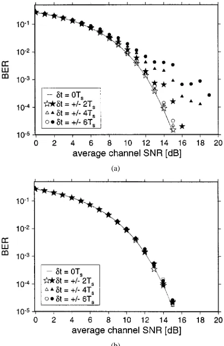
Fig. 2. BER versus channel SNR performance over AWGN channels for a 512-subcarrier OFDM modem employing DQPSK. Positive time shifts imply time-advanced receiver window or delayed received data.
error of between two adjacent subcarriers. If the time shift is an integer multiple of the sampling time , then the phase shift introduced between two consecutive
subcar-riers is , where is the FFT length employed.
This evolving phase error has a considerable influence on the BER performance of the OFDM system, clearly depending on the modulation scheme used. In a time-dispersive channel, the phase errors introduced by timing errors are superimposed on the channel’s frequency domain transfer function, and their ef-fect can be mitigated by differential encoding and detection, as will be demonstrated during our further discourse.
If the timing errors are so high that the FFT window of the receiver includes samples outside the data and guard segments of the current OFDM symbol, then the consecutive OFDM symbols interfere, severely affecting the system’s performance. When the guard interval is followed by the data samples, a moderately delayed FFT receiver window may overlap with the next OFDM symbol, while an early FFT window will include samples of the data segment and the guard interval. The latter case will not introduce any interference, while the former case is much more detrimental to the performance.
inter-OFDM symbol interference. A short cyclic postamble can be used to mitigate this effect for small timing errors. Fig. 2(b) depicts the performance of the modem using a cyclic postamble of ten samples, tolerating higher synchronization inaccuracies.
III. SYNCHRONIZATIONALGORITHMS
The results in Section II show that the accuracy of a modem’s synchronization system greatly influences the overall BER performance. We have seen that carrier frequency differences between the transmitter and the receiver of an OFDM system will introduce additional impairments in the frequency domain caused by intersubcarrier interference, while FFT window misalignments in the time domain will lead to phase errors between the subcarriers. Both these effects will degrade the system performance and have to be kept to a minimum by the synchronization system.
In a TDMA-based OFDM system, the frame synchronization between a master station—in cellular systems generally the base station (BS)—and the portable stations (PS) has to be also main-tained. For these systems, a BF reference symbol marking the beginning of a new time frame is commonly used. This added redundancy can be exploited for frequency synchronization and FFT-window alignment, if the reference symbol is correctly chosen.
In order to achieve synchronization with a minimal amount of computational effort at the receiver, while also minimizing the amount of redundant information added to the data signal, the synchronization process is normally split into an acquisition phase and a tracking phase, if the characteristics of the random frequency and timing errors are known. In the acquisition phase, an initial estimate of the errors is acquired, using more complex algorithms and possibly a higher amount of synchronization in-formation in the data signal, whereas later the tracking algo-rithms only have to correct for small short-term deviations.
At the beginning of the synchronization process, neither the frequency error nor the timing information are known, hence synchronization algorithms must be found that are sufficiently robust to initial timing and frequency errors.
A. Coarse Frame and OFDM Symbol Synchronization
Coarse frame and symbol synchronization algorithms pre-sented in the literature all rely on additional redundancy in the transmitted data stream. Claßen and Meyr [37] proposed an OFDM frame synchronization burst of at least three OFDM symbols per frame. Brüninghaus [24] suggested a reference symbol for easy frequency-domain frame start detection. For the ALOHA environment, Warner [38] proposed the use of a power detector and the subsequent correlation of a set of received synchronization tone phasors—embedded in the data symbols—with the known synchronization reference phasors. The received synchronization tones are extracted from the received time-domain signal using an iterative algorithm for
Fine symbol tracking algorithms are generally based on cor-relation operations either in the time or in the frequency main. Warner [38] and Bingham [39] employed frequency do-main correlation of the received synchronization pilot tones with known synchronization sequences, while de Couasnon [40] uti-lized the redundancy of the cyclic prefix by integrating over the magnitude of the difference between the data and the cyclic ex-tension samples. Sandell et al. [41] and van de Beek et al. [42] proposed using the autocorrelation properties of the received time-domain samples, imposed by the cyclic extension, for fine time tracking.
C. Frequency Acquisition
The frequency acquisition algorithm has to provide an initial frequency error estimate, which is sufficiently accurate for the subsequent frequency tracking algorithm to support fine tracking. Generally the initial estimate must be accurate to half a subcarrier spacing. Sari [36] proposed the use of a pilot tone embedded into the data symbol, surrounded by virtual subcar-riers, so that the frequency-shifted pilot can be located easily by the receiver. Moose [43] suggested a shortened repeated OFDM symbol pair, analogous to his frequency tracking algorithm to be highlighted in the next section. By using a shorter DFT for this reference symbol pair, the subcarrier distance is increased and thus the frequency error estimation range is extended. Claßen and Meyr [37], [44] proposed binary pseudonoise (PN) or so-called CAZAC training sequences carried by synchro-nization subcarriers, which can also be invoked for frequency tracking. Their frequency acquisition, however, is performed by a search for the training sequence in the frequency domain. This is achieved by means of frequency-domain correlation of the received symbol with the training sequence. Schmidl [45] suggests a blind algorithm for PSK or Star-QAM [2] modulation to resolve the ambiguity of the fine frequency synchronization algorithm proposed by Sandell [41] by a blind frequency error estimation step after the fine synchronization is performed. For burst-by-burst OFDM transmission, algorithms including a time-domain training sequence known to the receiver and preceeding the OFDM transmission bursts have been suggested by Lambrette et al. [46] and Házy [47].
D. Frequency Tracking
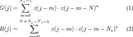
Fig. 3. Time synchronization. Plots of the correlation termsR(j) and G(j) from (1) and (2) for two consecutive 64-slot TDD frames under perfect channel conditions. The peaks indicate the correct TDD frame and OFDM symbol synchronization instants, respectively.
autocorrelation function, which represents a phase shift be-tween the received data samples and their repeated copies in the cyclic extension of the OFDM symbols.
E. OFDM Synchronization by Autocorrelation
Both the frequency- and the time-synchronization control sig-nals in the tracking mode can be derived from the received signal samples’ cyclic nature, exploiting the OFDM symbols’ cyclic time domain extension by means of correlation techniques. Orig-inally, Moose [43] proposed a synchronization algorithm using repeated data symbols, and methods for the frequency error esti-mation employing the cyclic extension of OFDM symbols were presented by Daffara et al. [48] and Sandell et al. [41], [42]. The frequency acquisition and frame synchronization proposed here are based on similar principles, employing a dedicated reference symbol exploited in the time domain [49].
No added redundancy in the data symbols and no a priori knowledge of the synchronization sequences employed in the reference symbol is required, since only the repetitive proper-ties of the OFDM symbols and those of the reference symbol (REF) in the proposed adaptive time division duplex (TDD) frame structure seen in Fig. 3 are exploited. All the processing is carried out in the time domain; hence, no FFT-based demod-ulation of the reference symbol is necessary.
F. Multiple Access Frame Structure
The proposed multiple access frame structure is depicted at the top of Fig. 3, which is constituted by a null, reference, and 62 data symbols. The reference symbol is transmitted once per 64-symbol frame by the base station, and it is employed by the mobile stations in downlink synchronization.
[image:4.612.326.532.62.120.2] [image:4.612.305.555.164.252.2]1) The Reference Symbol: The proposed reference symbol shown in Fig. 4 was designed to assist in the operation of the synchronization scheme, and it consists of repetitive copies of a synchronization pattern SP of complex pseudorandom sam-ples. As seen in the figure, the reference symbol is padded with
Fig. 4. Reference symbol, consisting of consecutive copies of a synchroni-zation pattern (SP) in the time domain.
Fig. 5. Schematic plot of the computation of the correlation functionG(j). The gray area represents the memory of the shift register.
negated copies of the synchronization pattern. The synchroniza-tion algorithm at the receiver needs no knowledge of the em-ployed synchronization pattern, hence this sequence could be used for channel sounding training sequences or for base station identification signals. Note that there are three hierarchical pe-riodic time-domain structures in the proposed framing scheme: the short-term intrinsic periodicity in the reference symbol of Fig. 4, the medium-term periodicity associated with the quasi-periodic extension of the OFDM symbols, and the long-term pe-riodicity of the OFDM frame structure, repeating the reference symbol every 64 OFDM symbols, as portrayed in Fig. 3. The long-term reference symbol periodicity is exploited to main-tain OFDM frame synchronization, while the medium-term syn-chronism of the cyclic extension assists in the process of OFDM symbol synchronization. A detailed discussion of this figure will be provided during our further discourse. Let us initially con-sider the macroscopic structure of the synchronization system in the next section.
2) Correlation Functions: The proposed synchronization algorithms rely on the evaluation of the correlation functions and , where is the index of the most recent input sample:
(1)
(2)
and represents the received complex signal samples, is the number of subcarriers per OFDM symbol, is the length of the cyclic extension, and is the periodicity within the ref-erence symbol, as seen in Fig. 4. The asterisk denotes the con-jugate of a complex value.
[image:4.612.329.553.568.630.2]frequency-synchronization error, let us now concentrate on how the synchronization algorithms rely on their evaluation.
G. Frequency Tracking and OFDM Symbol Synchronization
In this section, we consider details of the frequency tracking and OFDM symbol synchronization algorithms, which make use of , as defined by (1). This synchronization algorithm was originally proposed by Sandell et al. [41], and assumes that a synchronization acquisition step has reduced the frequency error to be estimated to be less than half a subcarrier distance.
1) OFDM Symbol Synchronization: The magnitude of is maximum, if is the last sample of the current OFDM symbol, since then the guard samples constituting the cyclic extension and their copies in the current OFDM symbol are perfectly aligned in the summation windows. Fig. 3 shows the simulated magnitude plots of and for two consecutive
transmission frames, with and , under
perfect channel conditions. The observed correlation peaks of can be easily identified as the last sample of an OFDM symbol. The amplitudes of the correlation peaks fluctuate, since the transmitted OFDM data symbols differ. The correlation peak magnitude is equal to the energy contained in the samples of the cyclic extension, and averages 50 for our system with
and an average sample power of 1.
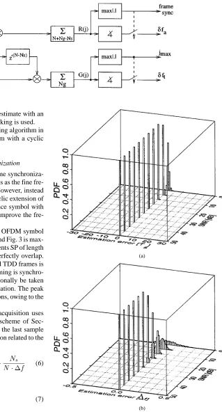
The simulated accuracy of the OFDM symbol synchroniza-tion in an AWGN channel is characterized in Fig. 6(a), where using a Gaussian channel was justified by the fact that the proposed synchronization schemes were initially tested in a 310-Mb/s data-rate portable wireless asynchronous transfer mode (WATM) system employing a high-gain directional antenna. This was necessary in order to maintain a realistic power budget design and support a bandwidth of 200 MHz, guaranteeing near-Gaussian channel conditions. In Section IV, however, we will characterize the peformance of our algorithm over fre-quency-selective Rayleigh channels. Observe in Fig. 6(a) that for SNRs in excess of about 7 dB, the histogram is tightly concen-trated around the perfect estimate, typically resulting in OFDM symbol timing estimation errors below . However, since even slightly misaligned time domain FFT-windows cause phase errors in the frequency domain, this estimation accuracy can be improved by low-pass filtering the associated error estimates. Let us now concentrate on the issues of frequency tracking.
2) Frequency Tracking: A carrier frequency error of re-sults in an evolving phase error of the received samples :
(3)
(4)
Clearly, the phase error difference between two samples and is a function of the frequency error and their time
delay, and is given by .
If the original phase difference between the two symbols and is known, and all other phase distortion is absent,
(a)
[image:5.612.303.551.58.491.2](b)
Fig. 6. Histogram of the simulated timing and frequency tracking errors for an OFDM modem usingN = 512 and N = N = 50 over AWGN channels.
then the phase difference error can be used to determine the frequency error .
As the time-domain samples of the cyclic extension or the guard interval are known to be a copy of the last data samples of the OFDM symbol, the frequency error can be estimated using each of these pairs of identical samples. To improve the estimation accuracy when exposed to noise and other channel impairments, averaging can be carried out over the estimates.
The phase of at equals the averaged phase
shift between the guard time samples and the corresponding data samples of the current OFDM symbol. As the corresponding sample pairs are spaced by samples, rearranging (4) leads to the fine frequency error estimation given by
(5)
ac-Fig. 7. Block diagram of the synchronization algorithms.
quisition must ensure a rough frequency error estimate with an accuracy of better than , if frequency tracking is used.
Fig. 6(b) shows the performance of the tracking algorithm in an AWGN channel for a 512-subcarrier modem with a cyclic extension length of 50 samples.
H. Frequency Acquisition and Frame Synchronization
Our proposed frequency acquisition and frame synchroniza-tion techniques are based on the same algorithms as the fine fre-quency and OFDM symbol synchronization. However, instead of using the medium-term periodicity of the cyclic extension of the OFDM data symbols, the dedicated reference symbol with shorter cyclic period is exploited to improve the fre-quency capture range.
1) Frame Synchronization: Similarly to the OFDM symbol synchronization, the magnitude of in (2) and Fig. 3 is max-imum, when the periodic synchronization segments SP of length of the reference symbol shown in Fig. 4 perfectly overlap. Again, the magnitude of for two simulated TDD frames is shown at the top of Fig. 3. The OFDM frame timing is synchro-nized with the peak of , which can additionally be taken into account for the OFDM symbol synchronization. The peak height is constant under perfect channel conditions, owing to the fixed reference symbol.
2) Frequency Acquisition: The frequency acquisition uses the same principle as the frequency tracking scheme of Sec-tion III-G-2. Specifically, the phase of at the last sample of the reference symbol contains information related to the frequency error:
(6)
leading to
(7)
Because the spacing between the sample pairs used in the compu-tation of is smaller than in the case of , which was used for the frequency tracking , the maximum detectable
frequency error is now increased from to ,
where is the subcarrier spacing of the OFDM symbols. 3) Block Diagram of the Time-Domain Synchronization Algorithms: In summary of our previous elaborations, Fig. 7 shows the detailed block diagram of the synchronization algo-rithms. The received samples are multiplied with the complex
(a)
(b)
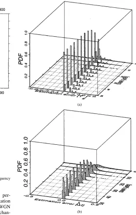
Fig. 8. Simulated frequency and time synchronization acquisition error histo-grams for the reference-symbol-based synchronization algorithm in an AWGN channel.
[image:6.612.228.547.59.654.2](a)
[image:7.612.47.333.60.416.2](b)
Fig. 9. Short WATM channel: (a) Impulse response. (b) Unfaded frequency domain channel transfer functionH(n).
4) Synchronization Acquisition Performance: The per-formance of the joint frequency- and time-synchronization acquisition algorithm described above was studied in AWGN channels as well as in a time-dispersive Rayleigh fading chan-nel. Fig. 8 shows the estimation error histograms for both the time and the frequency synchronization in an AWGN channel. It can be seen that the time-synchronization algorithm shows good estimation accuracy for all observed values of SNR, with no timing estimation errors of more than observed for SNR values above 5 dB. The frequency estimation accuracy, depicted in Fig. 8(b), shows very good performance with estimation errors restricted to below 10% of the subcarrier distance for SNR values of more than 5 dB, and errors of less than 5% for SNR values of 10 dB or more.
The time-dispersive Rayleigh fading channel employed for the simulations is assumed to be an indoors channel for a WATM system, operating at 60 GHz with a sample rate of 225 MHz. Fig. 9 shows the unfaded impulse response consisting of three paths and the corresponding frequency domain channel transfer function. Each of the paths is multiplied by an independent Rayleigh fading function of a normalized Doppler frequency of , which corresponds to a worst-case vehicular ve-locity of 50 km/h or 13.89 m/s.
The synchronization acquisition error histogram for the ref-erence symbol based algorithm in the time-dispersive Rayleigh fading channel is depicted in Fig. 10. Fig. 10(a) shows the timing
(a)
(b)
Fig. 10. Simulated frequency and time synchronization acquisition error histo-grams for the reference-symbol-based synchronization algorithm in the time-dispersive Rayleigh fading channel.
estimation errors, where the first arriving path was assumed to be the correct synchronization. The algorithm seeks to synchro-nize not on the first but on the path with the highest amplitude, which results in the histogram in Fig. 10(a) being spread over the duration of 11 sampling periods of the impulse response. The frequency estimation errors, shown in Fig. 10(b), exhibit larger variations than in the AWGN channel, even for high SNR values. The estimation errors are below 5% of the subcarrier spacing for SNR values above 20 dB, but are much higher for lower SNR values.
IV. SYSTEMBER PERFORMANCE WITHTIME ANDFREQUENCY ACQUISITION INTIME-DISPERSIVEFADINGCHANNEL
[image:7.612.268.546.61.499.2]Fig. 11. BER versus channel SNR performance curves for the 512-subcarrier OFDM system in the presence of a fixed frequency error of 0:31f in the time-dispersive Rayleigh fading channel. The lines indicate the performance for the perfectly synchronized system, while the markers indicate the performance of the OFDM modem employing the reference-symbol-based synchronization acquisition algorithm. Coherent detection of the received symbols with 64 pilot tone channel estimation was assumed in both cases.
reference and one data symbol per 64-slot TDMA frame. For each frame, the frequency and timing acquisition was performed using the reference symbol, and the data symbol was demodu-lated using the estimated values for the time and frequency er-rors. No averaging was performed for the estimated values.
The simulated OFDM symbols consisted of a 512-subcarrier data segment, with a cyclic preamble of 64 and a cyclic post-amble of ten samples. The postpost-amble helps avoid inter-OFDM symbol interference for small timing synchronization errors. The channel employed for these simulations was the three-path model depicted in Fig. 9(a) with the same fading parameters as listed above.
Coherently detected BPSK. QPSK and 16-QAM were assumed for data transmission over the subcarriers, and the channel estimation was performed with 64 frequency-domain pilot tones spread across the OFDM bandwidth. The pilot-based channel estimation not only tries to cancel out the frequency-domain fading effects due to the channel’s impulse response, but also corrects the phase errors caused by moderate errors of the timing synchronization. A constant frequency error of was assumed for the simulation.
The symbols in Fig. 11 show the BER performance of the OFDM modem employing the acquisition algorithm for syn-chronization in the fading time-dispersive channel, compared to the ideally synchronized modem with the same pilot-based channel estimation, which are represented by the continuous lines. It can be seen that for all SNR values, the perfectly syn-chronized system performs marginally better than the acquired synchronized one, for all studied modulation schemes. The dif-ference between the two systems’ performance is, however, very small for SNR values of up to 30 dB for BPSK and QPSK. 16-QAM shows greater sensitivity for synchronization-error in-duced noise, and suffers a maximum SNR loss of about 1 dB.
For very high SNR values, the residual synchronization errors that can be observed in Fig. 10 significantly influence the system’s performance, resulting in residual BER values between about for 16-QAM and for BPSK. In
prac-tical systems, however, the error correction coding employed for data transmission can suppress the difference in raw BER performance.
V. DISCUSSION ANDCONCLUSION
We have presented a Reference-symbol-based joint time- and frequency-synchronization acquisition algorithm for the down-link of OFDM systems. The system performance employing this algorithm in a time-dispersive Rayleigh fading WATM channel has been shown to be very close to the perfectly synchronized modem, and it can be used without a subsequent fine synchro-nization tracking stage, if the frequency and timing parameters are not significantly varying during the delay between the refer-ence and the data symbols. The proposed combination of tech-niques is widely applicable, provided that the corresponding system parameters, such as the pre- and postamble duration, the number of frequency-domain pilot symbols, and the design of the reference symbol are appropriately adjusted. Our future work is focused on researching burst-by-burst adaptive OFDM systems, exploiting the time-variant fluctuation of the channel’s frequency-selective frequency-domain transfer function.
ACKNOWLEDGMENT
The authors thank the EPSRC, U.K., and the Median and First European Consortium partners, in particular, to J. Borowski, S. Zeisberg, and numerous other professional friends for fruitful discussions.
REFERENCES
[1] R. W. Chang, “Synthesis of band-limited orthogonal signals for multi-channel data transmission,” Bell Syst. Tech. J., vol. 46, pp. 1775–1796, Dec. 1966.
[2] L. Hanzo, W. Webb, and T. Keller, Single- and Multicarrier Quadrature
Amplitude Modulation. Chichester, U.K.: Wiley–IEEE Press, 2000. [3] T. Keller and L. Hanzo, “Adaptive multicarrier modulation: A
conve-nient framework for time-frequency processing in wireless communica-tions,” in Proc. IEEE, vol. 88, May 2000, pp. 611–642.
[4] M. S. Zimmermann and A. L. Kirsch, “The AN/GSC-10/KATHRYN/ variable rate data modem for HF radio,” IEEE Trans. Commun. Technol., vol. CCM-15, Apr. 1967.
[5] E. N. Powers and M. S. Zimmermann, “A digital implementation of a multichannel data modem,” in Proc. IEEE Int. Conf. Commun., Philadel-phia, PA, 1968.
[6] B. R. Saltzberg, “Performance of an efficient parallel data transmission system,” in IEEE Trans. Commun. Technol., Dec. 1967.
[7] R. W. Chang and R. A. Gibby, “A theoretical study of performance of an orthogonal multiplexing data transmission scheme,” IEEE Trans.
Commun. Technol., vol. COM-16, Aug. 1968.
[8] S. B. Weinstein and P. M. Ebert, “Data transmission by frequency di-vision multiplexing using the discrete Fourier transform,” IEEE Trans.
Commun. Technol., vol. COM-19, pp. 628–634, Oct. 1971.
[9] A. Peled and A. Ruiz, “Frequency domain data transmission using re-duced computational complexity algorithms,” in Proc. ICASSP, 1980, pp. 964–967.
[10] B. Hirosaki, “An orthogonally multiplexed QAM system using the discrete Fourier transform,” IEEE Trans. Commun., vol. COM-29, pp. 983–989, July 1981.
[11] H. J. Kolb, “Untersuchungen über ein digitales Mehrfrequenzverfahren zur Datenübertragung,” Ausgewählte Arbeiten über Nachrichtensys-teme, Universität Erlangen-Nürnberg, no. 50.
[12] H. W. Schüssler, “Ein digitales Mehrfrequenzverfahren zur Datenüber-tragung,” in Professoren-Konferenz, Stand und Entwicklungsaussichten
COM-33, pp. 665–675, July 1985.
[15] F. Mueller-Roemer, “Directions in audio broadcasting,” J. Audio Eng.
Soc., vol. 41, no. 3, pp. 158–173, Mar. 1993.
[16] G. Plenge, “DAB—A new radio broadcasting system—State of devel-opment and ways for its introduction,” Rundfunktech. Mitt, vol. 35, no. 2, p. 45, 1991.
[17] M. Alard and R. Lassalle, “Principles of modulation and channel coding for digital broadcasting for mobile receivers,” EBU Review, pp. 47–69, Aug. 1987. Tech. 224.
[18] “DAB,” in Proc. 1st Int. Symp., Montreux, Switzerland, June 1992. [19] I. Kalet, “The multitone channel,” IEEE Trans. Commun., vol. 37, pp.
119–124, Feb. 1989.
[20] M. V. B. T. Pollet and M. Moeneclaey, “Ber sensitivity of pfdm sys-tems to carrier frequency offset and Wiener phase noise,” IEEE Trans.
Commun., vol. 43, pp. 191–193, Feb. 1995.
[21] K. Fazel and G. Fettweis, Eds., Multi-Carrier Spread-Spec-trum. Norwell, MA: Kluwer, 1997, p. 260.
[22] ETSI, “Digital video broadcasting (DVB); framing structure, channel coding and modulation for digital terrestrial television,” EN 300 744 V1.1.2, Aug. 1997.
[23] D. Sommer and G. P. Fettweis, “OFDM-Übertragung im 60-ghz-Indoor-Bereich,” in 3. OFDM Fachgespräch in Braunschweig, 1998. [24] K. Brüninghaus and H. Rohling, “Verfahren zur
Rahmensynchroniza-tion in einem OFDM-System,” in 3. OFDM Fachgespräch in
Braun-schweig, 1998.
[25] M. Lampe and H. Rohling, “Aufwandsgünstige Verfahren zur Reduktion der Außerbandstrahlung in OFDM-Funkübertragungssystemen,” in 3.
OFDM Fachgespräch in Braunschweig, 1998.
[26] E. Hallmann and H. Rohling, “OFDM-Vorschläge für UMTS,” in 3.
OFDM Fachgespräch in Braunschweig, 1998.
[27] T. May and H. Rohling, “Zur Detektion differentialler modulation in codierten OFDM-Systemen,” in 3. OFDM Fachgespräch in
Braun-schweig, 1998.
[28] R. Grünheid and H. Rohling, “Ein OFDM-FDMA-Konzept für den Up-link eines Kommunikationssystemes,” in 3. OFDM Fachgespräch in
Braunschweig, 1998.
[29] R. F. H. Fischer and J. B. Huber, “A new loading algorithm for discrete multitone transmission,” in Proc. Globecom, London, U.K., 1996. [30] A. Engelhart, W. G. Teich, and J. Lindner, “RNN-Empfangsalgorithmen
bei Paketübertragung mit Mehrträgerverfahren ohne Schutzzeit,” in 3.
OFDM Fachgespräch in Braunschweig, 1998.
[31] A. Dekorsy and K.-D. Kammeyer, “maximum-likelihood-de-codierung von höherstufig orthogonal modulierten Signalen bei einem OFDM-CDMA-System,” in 3. OFDM Fachgespräch in Braunschweig, 1998.
[32] H. Schmidt and K.-D. Kammeyer, “Adaptive Subträgerselektion zur Re-duktion des Crestfaktors bei OFDM,” in 3. OFDM Fachgespräch in
Braunschweig, 1998.
[33] J. Borowski, S. Zeisberg, J. Hübner, K. Koora, E. Bogenfeld, and B. Kull, “Performance of OFDM and comparable single carrier system in MEDIAN demonstrator 60 GHz channel,” in Proc. ACTS Summit, Aal-borg, Denmark, Oct. 1997, pp. 653–658.
[34] J. G. Proakis, Digital Communications, 2nd ed. London, U.K.: Mc-Graw-Hill, 1989.
[35] P. R. K. Fazel, S. Kaiser, and M. Ruf, “A concept of digital terrestrial television broadcasting,” Wireless Personal Commun., vol. 2, pp. 9–27, 1995.
[36] I. J. H. Sari and G. Karam, “Transmission techniques for digital terres-trial tv broadcasting,” IEEE Commun. Mag., pp. 100–109, Feb. 1995. [37] F. Claßen and H. Meyr, “Synchronization algorithms for an ofdm system
for mobile communications,” in Codierung für Quelle, Kanal und
Über-tragung. Berlin: VDE-Verlag, 1994, vol. 130, ITG Fachbericht, pp. 105–113.
[38] W. D. Warner and C. Leung, “Ofdm/fm frame synchronization for mo-bile radio data communication,” IEEE Trans. Veh. Technol., vol. 42, Aug. 1993.
[39] J. Bingham, “Method and apparatus for correcting for clock and carrier frequency offset, and phase jitter in multicarrier modems,” U.S. Patent 5206886, Apr. 27, 1993.
[40] R. M. T. de Couasnon and J. Rault, “Ofdm for digital tv broadcasting,”
Signal Processing, vol. 39, pp. 1–32, 1994.
cessing, vol. 45, pp. 1800–1805, July 1997.
[43] P. H. Moose, “A technique for orthogonal frequency division multi-plexing frequency offset correction,” IEEE Trans. Commun., vol. 42, pp. 2908–2914, Oct. 1994.
[44] F. Claßen and H. Meyr, “Frequency synchronization algorithms for ofdm systems suitable for communication over frequency selective fading channels,” in Proc. IEEE Veh. Technol. Conf., 1994, pp. 1655–1659.
[45] T. M. Schmidl and D. C. Cox, “Blind synchronization for OFDM,”
Elec-tron. Lett., vol. 33, pp. 113–114, Jan. 1997.
[46] U. Lambrette, M. Speth, and H. Meyr, “OFDM burst frequency synchro-nization by single carrier training data,” Commun. Lett., Mar. 1997. [47] L. Házy and M. El-Tanany, “Synchronization of OFDM systems over
frequency selective fading channels,” in Proc. 47th Veh. Technol. Conf., Phoenix, AZ, May 1997, pp. 2094–2098.
[48] F. Daffara and O. Adami, “A new frequency detector for orthogonal multicarrier transmission techniques,” in Proc. IEEE 45th Veh. Technol.
Conf., Chicago, IL, July 15–28, 1995, pp. 804–809.
[49] T. Keller and L. Hanzo, “Orthogonal frequency division multiplex synchronization techniques for wireless local area networks,” in Proc.
7th Conf. Personal Indoor and Mobile Radio Communications, Taipei,
Taiwan, R.O.C., Oct. 1996, pp. 963–967.
[50] D. R. Gimlin, “On minimizing the peak-to-average power ratio for the sum ofN sinusoids,” IEEE Trans. Commun., vol. 412, pp. 631–635, Apr. 1993.
[51] P. Mandarini and A. Falaschi, “Performance analysis of a fine frequency error estimator for OFDM transmission,” in Proc. ACTS Summit, Granada, 1996.
Thomas Keller studied electrical engineering at the University of Karlsruhe, Ecole Superieure d’Ingenieurs en Electronique et Electrotechnique, Paris, and received the Dipl.-Ing. degree from the University of Southampton; and the Ph.D. degree in mobile communications from the Wireless Multimedia Communications Group, University of Southampton.
He recently joined Ubinetics, Cambridge, U.K. His current areas of interest include adaptive OFDM transmission, wide-band channel estimation, and error correction coding.
Lorenzo Piazzo was born in Rome, Italy, in 1964. He received the “Laurea” degree in electronic engi-neering and the “dottorato” degree in telecommuni-cations from the University of Rome “La Sapienza” in 1991 and 1995, respectively.
From 1994 to 1996, he was with “Space Engi-neering.” Since 1997, he has been a Researcher with the INFOCOM Department, University of Rome. In 1999, he was a Visiting Scientist with the Department of ECS, University of Southampton, U.K. His research interests include speech coding, channel coding, and OFDM modulation.
Paolo Mandarini was born in Rome, Italy, in 1940. He received the Laurea degree in electronic engineering from the University of Rome “La Sapienza” in 1963.
Lajos Hanzo (M’91–SM’92), received the degree in electronics in 1976 and the Ph.D. degree in 1983, both from the Technical University of Budapest, Hungary.