Abstract — Air springs are widely adopted to insulate objects that need to be protected from vibration and mechanical shock. Their axial behaviour can be studied by means of appropriate models; anyhow, manufacturers provide experimental test results and the design criteria to properly choose the component.
If the spring does not work only along its axial direction, it is necessary to define the transverse behaviour. It depends on axial load that should not reach excessive values for which the system may become statically unstable.
The paper reports the results of an experimental investigation, conducted on two types of air springs, convoluted and rolling, to check the spring behaviour to variable transverse excitation, for different values of the constant compression load.
Index Terms — Convoluted air springs, rolling air springs, shear stiffness, stability, vibration and shock isolation
I. INTRODUCTION
ir springs are widely used as vibration isolators and mechanical shock absorbers for fixed installations and are often preferred to the solid springs as they can be used as self-levelling system, with isochrones characteristics.
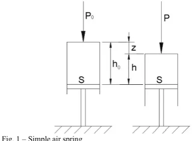
To characterize the axial behaviour of an air spring, in first approximation, it is possible to refer to a piston-cylinder system filled with air (Fig.1). In this case, the main parameters that characterize the behaviour of the spring are the piston area, the air pressure and the internal volume.
In the classical air spring model [1], it is assumed that the air in the cylinder follows a polytropic process. The relationships between two states is therefore:
p=po(Vo/V) , (1) being Vo, Po the volume and the pressure of the initial state. The polytropic index, may be assumed equal to 1.41 (adiabatic process) if the volume changes rapidly, and it is therefore possible to neglect the heat exchanged with the
Manuscript received March 20, 2017; revised March 29, 2017. G. Di Massa is with the Dipartimento di Ingegneria Industriale, Università degli Studi di Napoli Federico II, 80125 ITALY, (e-mail: [email protected]).
S. Pagano is with the Dipartimento di Ingegneria Industriale, Università degli Studi di Napoli Federico II, 80125 ITALY, (e-mail: [email protected]).
S. Strano is with the Dipartimento di Ingegneria Industriale, Università degli Studi di Napoli Federico II, 80125 ITALY, (e-mail:[email protected]).
[image:1.595.303.499.215.358.2]environment. For air springs isolators the polytropic index is generally assumed equal to 1.38.
Fig. 1 – Simple air spring
Denoting with P=pS the load acting on the spring, it follows (Fig. 1):
0 0 0 0 0 0
0 VV P hh z P 1 z1/h
P
P (2)
Deriving expression (2), with respect to compression z, the air spring axial stiffness, k, results:
z h P h z h P dz dP kz 0 1 0 0 0 )] / ( 1 [ 1
(3)
The stiffness depends on the load P and on the spring compression, z= z(P).
The natural circular frequency, z, of a SDF system constituted by a suspended mass (m = P/g) on air springs, in case of small amplitude oscillations in the neighbourhood of the equilibrium configuration, is:
z h g P g k m k
z
0
(4)
Expression (4) shows that the system is not isochronous as the natural circular frequency varies with the compression, z.
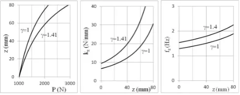
Fig. 2 reports the following trends:
- spring compression (z=ho-h) vs axial load, P; - axial spring stiffness vs compression; - system natural frequency vs compression.
The diagrams were obtained for the following values: p0 = 2 bar; h0 = 150 mm; S = 5000 mm2. Two limit
behaviours have are considered: isothermal (=1) and adiabatic process (=1.41).
Stability Analysis of Air Springs Subjected to
Lateral Loads
G. Di Massa
Member IAENG,
S. Pagano, S. Strano
Fig. 2 – Compression, stiffness and natural frequency for S=cost
Simple air spring can be compensated; i.e. it is possible to maintain constant the spring height, even for different loads, by sending or withdrawing air from the spring. In this way, the spring has constant volume and variable air mass. From (3), setting z = 0, it follows:
0
h P
kz (5)
or, equivalently, by setting: P = p·S; V = S·ho:
V S p
kz 2 (6)
In this case, the natural circular frequency of the system, in case of small oscillations in the neighbourhood of ho, is isochronous (not load dependent):
0
h g m kz z
(7)
Unlike the piston-cylinder system (Fig. 3a), whose transversal area is constant, commercial air springs (Fig. 3b and Fig. 3c) are characterized by a deformable elastomeric element (bellows). Therefore, the loaded area (or effective area) is not constant, but it depends on the deformation of the bellows.
[image:2.595.309.543.73.155.2]From the geometric point of view, the effective area can be considered as the circular area, locus of the points where the tangent to the deformable bellows curvature is perpendicular to the load direction. It is experimentally determined as the ratio between the load acting on the spring and the internal pressure. Fig. 4shows that the effective area increases with compression for convoluted air springs.
Fig. 3 – Effective area diameter for different types of air spring: a) simple air spring; b) convoluted air spring; c) rolling air spring.
Even in this case, Eq. (6) define the spring axial stiffness if, in place of the constant area S, it is considered the
effective area Se, depending on the spring compression: kz = p Se2/V (8)
Fig. 4 – Effective area depending of the spring deformation.
Eq. (8) put in evidence that it is possible to reduce the stiffness of the spring by increasing the volume V, by connecting the spring with an auxiliary reservoir (Fig.5) of suitable capacity [2]. In such a case, it is also possible to vary the damping, by suitably adjusting the section of the orifice placed in the duct connecting the spring with the reservoir.
Fig. 5 – Air spring with auxiliary air reservoir
Commercially air springs are mainly of two types:
- convoluted air spring (Fig. 3b) that allows to obtain high stroke with reduced height of the spring;
- rolling air spring (Fig. 3c) in which the bellows rolls on the piston; the geometry of the piston determines the effective area change with the spring compression , and then the spring characteristics.
The two types of springs have different behaviours as the effective area changes in a different way with compression; in the convoluted springs, the effective area grows qualitatively according to Fig. 6a while for rolling springs the trend can vary in a considerably way, depending on the piston geometry (Fig. 6b).
[image:2.595.312.548.580.694.2]a) b)
Fig. 6 – Effective area vs spring height for convoluted (a) and rolling (b) air spring
II. AIR SPRING HORIZONTAL STIFFNESS
[image:2.595.54.286.623.725.2]buckling. In other applications, the relative transversal displacement between the end plates is not constrained, as in the case of vibration insulation of machinery or structures containing devices sensitive to accelerations [3] and the spring has to absorb the shear action.
Fig. 7 – Air spring a) inserted in a linkage and b) not inserted in a linkage
In this last case, the end plates can accomplish significant relative cross offsets (Fig. 7b) and it is therefore necessary to know the transverse stiffness of the spring.
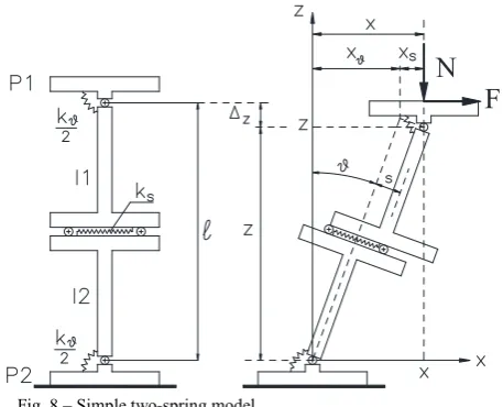
The simple two-spring model[4, 5] proposed by Koh and Kelly for elastomeric seismic isolators, could explain the combination effect of axial and transverse load. The isolator is schematically represented (Fig. 8) by means of a set of rigid bodies forming a two degrees of freedom system. The relative movements are counteracted by lumped stiffnesses arranged to react, separately, to bending and shear loads. Even in the case of reinforced elastomeric seismic isolators, the axial deformability is neglected, as it is small compared to shear and bending ones. In the case of the air springs, the axial deformation may be recovered by charging or discharging the air spring.
The two end plates (P1 and P2) are constrained to remain parallel, connected to two intermediate elements (I1 and I2), by means of hinges. The relative rotations (q) are countered by two rotational springs, having stiffness kq /2, representing the spring bending stiffness.
A liner guide connects the two intermediate elements. The relative sliding is contrasted by a spring whose stiffness, ks, represents the spring shear stiffness.
F
N
Fig. 8 – Simple two-spring model
If the device is subjected to the single transverse force F, in the hypothesis of small displacements, the overall transverse stiffness is then given by the series of the two stiffness (bending and shear):
s x
k k k 1/ 1 1
(9)
The effect of the axial load N on the overall horizontal stiffness may be highlighted considering separately bending and shear stiffness. The transverse displacement of the upper plate P1, with respect to the lower plate, is given by the sum of two contributions (Fig. 8):
x
x
x
s. It follows:s l s
l x x
x s sin cos (10) Assuming an infinite ks stiffness, the equilibrium condition leads to:
; sin
cosNl k
Fl (11)
From Eq. (10), considering small angles q, and dividing the expression for the displacement xq, the spring transversal stiffness results:
2 l
Nl k x
F kx
(12)
It follows that, neglecting the shear deformability, the system is stable if kq > Nl. Under this hypothesis, the vertical load, Nq = kq/l, is therefore the spring buckling load.
Similarly, considering an infinite kq bending stiffness, the equilibrium condition, along the sliding direction, leads to:
s k N
Fcos sin s (13)
Under the hypothesis of small deformations, being: s≅lq and xs=s·cosq≅s, the horizontal stiffness, kxs, results:
l N k x F
k s
s
xs (14)
It follows that, neglecting the bending deformability, the system is stable if kq > N/l. The vertical load, Ns = ksl, represents the spring buckling load.
Eq. (12) and (14) shows that, increasing the vertical load N, the horizontal stiffness decreases until the static instability.
The spring transverse stiffness depends on its typology (convoluted or rolling) and, typically, it is lower than the axial stiffness. In some cases, the transverse stiffness is expressed as a percentage of that axial one [6]. For convoluted air springs, the transverse stiffness decreases with the number of convolutions; springs with three convolutions can have negative transverse stiffness and can only be used if guided by linkages preventing transverse relative translations between the end plates.
III. TEST DESCRIPTION
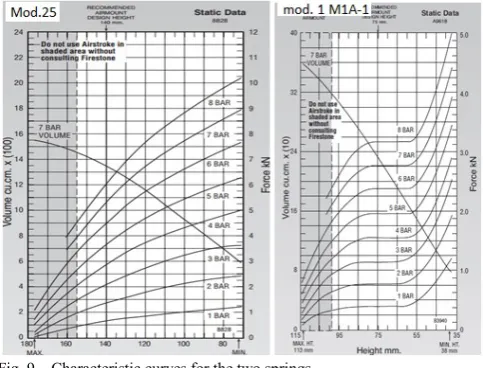
[image:3.595.49.278.494.679.2]rolling air spring (mod.1M1A-1). Fig. 9 shows the characteristic curves for their axial behaviour.
The transverse characteristics were defined using a biaxial press by which it was possible to assign a constant vertical load and impose a harmonic transverse motion. The apparatus consists of an 800 kN hydraulic press equipped with a slide that can translate on two linear duct trolleys and rails in horizontal direction. A mechanical actuator moves the slide with a harmonic motion of assigned amplitude and frequency (Fig. 10). The instrumentation enables the slide position and the force transmitted by the actuator to be detected.
The tests were conducted by fixing the air spring lower plate onto the horizontal slide and the upper plate to a vertical slide onto which acts the vertical load (Fig. 11).
[image:4.595.305.559.112.510.2]A horizontal harmonic movement of 8 mm amplitude (i.e. a stroke of 16 mm) with a frequency of 0.05 Hz was applied. It can be noted that the load cell is placed on the rod connecting the actuator to the slide. It therefore measures the spring transversal restoring force plus the inertia forces and the friction force due to the slide. The inertia forces are negligible, as the forcing frequency is very low while the friction force is evident in the Force-Displacement cycle, as it will be shown later; it is therefore possible to identify the contribution due to the spring.
Fig. 9 – Characteristic curves for the two springs
During the tests, the pressure inside the spring was also measured. In particular, the tests were performed following the subsequent steps:
- a reference height, h0, for each spring was established: 140 mm for the convoluted spring and 75 mm for rolling one;
- the spring was inflated until a desired pressure (in the range 2 - 5 bar);
- the tests were first performed by completely opening the valve connecting the spring to the compressed air cylinder of the compressor, having a capacity of 24 litres and, subsequently, with the valve completely closed. If the valve is closed (constant air mass), the pressure rapidly grows with the spring compression while, if it is open, the pressure slightly vary thank to the high capacity of the air reservoir with respect to that of the spring;
- the height of the spring was adjusted acting on the press, in a range of predefined values;
- the spring lower plate was driven to perform a horizontal harmonic motion;
[image:4.595.312.559.294.492.2]- the displacement of the bottom plate and the force needed to drive it, were detected to obtain the Force-Displacement cycle.
Fig. 10 – Test rig scheme
Fig. 11 – The test rig
IV. TESTS ON CONVOLUTED AIR SPRING
Here are shows the results of some tests conducted on the convoluted air spring (mod.25).
The first test was performed at a pressure of 3 bar, with a reference height of 140 mm and with the valve placed on the pipe connecting the air spring to the compressed air cylinder, completely closed.
Force-Displacement cycles (Fig.12) are characterized by two inclined and parallel branches, and by an almost vertical segment at the end of each stroke due to the inversion of the friction forces in the guides of the slide. Therefore, it is easy to quantify the friction force entity while the slope of the two branches can be attributed to the transverse stiffness of the spring.
[image:4.595.48.290.371.555.2]Fig. 12 – F-D cycle for convoluted air spring with: p=3bar @140 mm and fully closed valve (constant air mass)
The test was repeated by fully opening the valve and regulating the pressure so that it is equal to 3 bar at the height of 140 mm. In this case (Fig.13) the spring reaches the static stability threshold at the height of 100 mm.
Fig. 13 – F-D cycle for convoluted air spring with: p=3bar @140 mm and fully opened valve
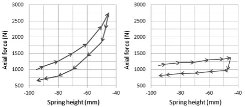
In the first case (closed valve) the spring exihibits an axial hardening behaviour as, the curve representing the elastic axial force against the vertical displacement, (Fig. 14a) has a progressively increasing trend. In the case of opened valve (Fig. 14b), the elastic axial force has an almost linear trend and therefore the stiffness is constant, not depending on compression.
Fig. 14 – Convoluted air spring - axial force vs spring height: a) fully closed valve e b) fully opened valve
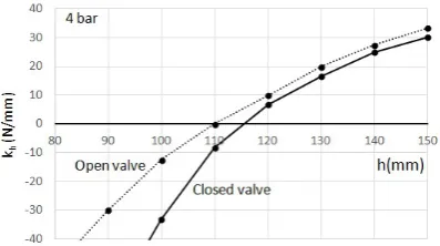
Analysing the slope of the branches of the Force-Displacement cycles, for different values of the height of the spring, the trend of the transverse stiffness, was evaluated. The corresponding diagrams, obtained for the two cases of valve fully closed and valve fully opened, are compared in Fig. 15. For each value of the height, the spring support a greater load if the valve is closed. For this reason the spring has a lower transversal stiffness if compared with the case of opened valve. The stiffness difference between the two cases is almost constant until the stability threshold.
[image:5.595.327.526.229.340.2]In the case of closed valve, the static instability is reached for larger values of the height as the correspondent axial load is greater.
Fig. 15 – Convoluted air spring - Transversal stiffness vs spring height: a) fully closed valve; b) fully opened valve.
V. TESTS ON ROLLING AIR SPRING
Similar tests were conducted on the rolling spring, Firestone, mod.1M1A-1, by adjusting the pressure at 3 bar for the spring height of 75 mm.
[image:5.595.47.290.338.524.2]The tests showed an opposite behavior to that of the convoluted springs. In fact, at least in the range of investigated horizontal displacements (± 8 mm), the transverse stiffness increases with the spring height reduction, due to the spring costruction criterion. For this type of spring the lower part of the bellows, being folded on itself, has a greater transverse stiffness compared to upper part. Therefore the transverse deformbility is mainly due to the upper part whose height decreases with the spring compression(Fig.16). For this geometric particularity, this type of air spring does not behave according to the model presented in par. II.
Fig. 16 – Rolling spring compression
[image:5.595.324.525.606.687.2] [image:5.595.50.290.657.758.2]The same tests were conducted with fully opened valve (Fig. 18) and, in this case, the increment of the horizontal stiffness, due to compression, is lower.
Even in this case the spring exihibit an axial hardening behaviour for closed valve (Fig. 19a) and constant axial stiffness in case of opened valve (Fig. 19b).
Even for this kind of spring, the test was repeated for different values of the spring height, to evaluate the trend of the transversal stiffness against the spring height. The comparison between the curve obtained with fully closed valve and that one relative to opened valve (nearly constant pressure) is reported in Fig. 20. Unlike the convoluted springs, the two curves have different opposite slopes and intersect at the height of about 80 mm. For small axial compression, the vertical stiffness is greater in the case of closed valve. Then the trend reverses.
Fig. 17 – F-D cycle for rolling air spring with: p=3bar @75 mm - fully closed valve
Fig. 18 – F-D cycle for rolling air spring with: p=3bar @75 mm - fully opened valve
[image:6.595.323.530.51.182.2]Fig. 19 – Rolling air spring - axial force vs spring height: a) fully closed valve e b) fully opened valve
Fig. 20 – Rolling air spring - Transversal stiffness vs spring height: a) fully closed valve; b) fully opened valve
VI. CONCLUSION
The adoption of the air springs for vibration isolation problems requires the knowledge of their transverse stiffness. This characteristic, not generally indicated in the brochures of the spring manufacturers, is a function of the spring height. In the cases examined, it was found that for convoluted air springs the transverse stiffness decreases with compression until the static stability threshold. On the contrary, in the case of rolling air springs, the transverse stiffness increases with compression. There are concerns with respect to the spring buckling but the increase of the stiffness may worsen the transversal vibration isolation.
ACKNOWLEDGMENT
The authors are grateful to Marco Di Pilla, Giuseppe Iovino and Gennaro Stingo for their collaboration during the setup construction and the execution of laboratory tests.
REFERENCES
[1] C. M. Harris, A.G. Piersol - Harris’ shock and vibration handbook, Fifth Edition, McGraw-Hill, 2002
[2] Quaglia G., Sorli M. – Air suspension dimensionless analysis and design procedure – Vehicle System Dynamics. Vol.35, pp.1777-1790 - 2001.
[3] M. De Michele , G. Di Massa, G. Frisella, S. Lippolis, S. Pagano, G. Pisani, S. Strano - A smart system for shock and vibration isolation of sensitive electronic devices on-board a vehicle - Advances in Italian Mechanism Science - Proceedings of the First International Conference of IFToMM Italy (IFIT2016) - Springer, pag. 503-511, ISBN 978-3-319-48375-7, Vicenza (Italy), 1-2 dec. 2016
[4] C.G. Koh, J. M. Kelly,. "Effects of axial load on elastomeric isolation bearings", Rep. No. UCB/EERC-86/12. Earthquake Engineering Research Center, University of California, Berkeley, 1987
[5] https://www.contitech.de/pages/produkte/schwingungstechnik/schwin gungstechnik-industrie/schwingung_projektierung_en.html
[image:6.595.50.277.252.338.2] [image:6.595.53.279.379.465.2] [image:6.595.47.288.504.609.2]