Microstrip Patch Antenna: Comparing Performance
of a Rectangular and a Circular Patch at LTE
Bluetooth and GSM Frequencies
Nsikan Nkordeh, Francis Idachaba, Oluyinka Oni
ABSTRACT: The demand for smaller, conformable antennas with desired properties has made antenna Engineers to device better ways of making antennas. The patch antenna comes to the rescue, as it provides the features needed in antennas used in the telecoms, meteorological and military industries, where light weight low profile antennas are required. The Microstrip patch antennas comes in different shapes and configuration, the most common being circular and rectangular. This paper takes a close look at the performance characteristics of the rectangular and circular Microstrip antennas , comparing different antenna parameters like directivity, E and H planes Half Power Beam Width (HPBW) vis-à-vis the dimensions and size( area of patch). Five frequencies (0.9Ghz,1.8Ghz ,1.9Ghz and 2.3Ghz and 2.4Ghz) are used in computing the configurations-these frequencies correspond to that of GSM, LTE and Bluetooth ; results from this paper can be used in building practical antennas for phones and laptops or any Bluetooth enabled device.
Keywords: Microstrip Patch Antenna, Rectangular, Circular Patch, Dielectrics.Directivity
I INTRODUCTION
Microstrip antennas are desirable due to their light weight, conformability and low cost. The Microstrip antenna is made up of a very thin metallic patch placed a small fraction of wavelength above a ground plane in a dielectric substrate ( , usually 0.003
0.005 , free space wavelength. For
example the rectangular patch antenna is approximately a-one half wavelength long section of a rectangular Microstrip line [1]. Microstrip Patch Antenna are typically used at frequencies between 1GHz to 100GHz.[1].The Microstrip patch antenna is designed so its pattern maxima is normal to the patch; this can be achieved by choosing the appropriate excitation technique.
N.S Nkordeh is a Lecturer with Department of Electrical and Information
Engineering Covenant University Ota Nigeria,
F. E Idachaba a Senior Lecturer with Department of Electrical and Information Engineering Covenant University Ota Nigeria,
O. O Oni is a Lecturer with Department of Electrical and Information
Engineering Covenant University Ota Nigeria,
The Microstrip patch antenna consist of a radiating patch on one side of the dielectric substrate which has a ground plane on the other side. Microstrip Patch Antennas come in conformable shapes like square, rectangle, elliptical, circular etc.
Microstrip Patch Antennas radiate primarily because of the fringing fields between the patch edge and the ground plane. In the design of patch antennas, there has to be a compromise between the antenna’s dielectrics value, dimensions (i.e. thickness and size) and the antenna performance-these variables affect the antenna performance. For good antenna performance, a dielectric with low value but high thickness is required, as this provide better efficiency, larger bandwidth and better radiation. However, such a design leads to antenna of larger size. In order to reduce the size, a higher dielectric constant should be used, but this results in a Microstrip with less efficiency and narrow bandwidth due to its high quality factor [[5]
Some advantages of Microstrip Patch Antenna
-Light weight and low volume
-Supports both dual and triple frequency operation
-Supports both linear and circular polarization
-low fabrication cost
-low profile planar configuration
Major disadvantages of MPA
-Narrow bandwidth
-Low efficiency
-Low gain
-Extraneous radiation from feeds and junctions
-Poor end fire radiator except for tapered slot antenna
-Lower power handling capacity
Microstrip Patch Antenna generally have very high quality factor (Q) .High Quality factor, which is inherent in Microstrip Patch Antenna leads to lower efficiency and narrow bandwidth. The Quality Factor represents the loss associated with the antenna; increasing the thickness of the dielectric substrate will reduce Q, but this will increase the size of the MPA. The surface wave contribution responsible for high Q can be reduced by the use of photonic bandgap structure [3]. To achieve high performance like high bandwidth, high efficiency, high gain vis-a-vis a conformably small size, the feeding method used is very important
II OPERATION OF A MICROSTRIP PATCH ANTENNA
A Microstrip Patch Antenna is made of a radiating patch placed on a dielectric substrate, with a ground plane on the other side. The EM waves fringe off the top parts into the substrate, reflecting off the ground plane and radiate off into the air. Electromagnetic radiation occurs mainly due to the fringing fields between the patch and the ground at the edges; this is because the dimensions of the patch are finite along the length and width. The amount of fringing depends on the ratio of patch length ( and substrate height ( . Since for Microstrip antennas / ≫ 1, fringing is reduced; this must be taken into account when designing as this influences the resonant frequency of the antenna. The region between the conducting patch and the ground plane acts as the region between a transmission line and the ground plane with both ends open, which leads to a standing waves in the dielectric. In designing a Microstrip Patch Antenna, we obtain both the effective dielectric constant (
and
dielectric (
)[6].
The
is needed to account
for the fringing fields and the wave propagation in
the line.
Most of the fields lie in the substrate while others line in the air; the phase velocity in air and in the substrate will be different, which makes it impossible for it to support pure Electric-Magnetic (TEM) mode of transmission. In analysis, we assume the quasi-TEM mode of transmission.). The value of the effective dielectric constant is usually constant at low frequencies, increasing monotonically as frequency increases, and ends up approaching the value of the dielectric constant at higher frequencies.For / 1,
⁄
1
The fringing effect causes the Microstrip patch look electrically bigger than its physical dimensions. In the analysis of the Patch, we take this into account by assuming an extension to the patch at both ends (for rectangular /square patch) ∆ ; ∆ is a function of the effective dielectric constant, , and the width-to-height ratio ( / and can be represented by the ratio
∆
0.412 0.3 0.264
0.258 0.8 2
For the dormant ,the effective Length of the patch is given by
2∆ 3
The resonant frequency is given by
1
2 √ 2 √ 4
is the velocity of light in free space. Equation (4) does not take account of the fringing effect. When the fringing effect is taking care of, (4) becomes
1 2
1
2 ∆
=
√ √ 5
Where
6
Note: As the substrate height increases, fringing also increases and leads to larger separation between the radiating edges and the lower resonant frequencies.
III DESIGN OF RECTANGULAR MICROSTRIP PATCH ANTENNA
In designing a rectangular Microstrip antenna, we specify some parameters: dielectric constant of the substrate, , the resonant frequency , , and the height of the substrate , .To obtain good impedance matching , an inset cut ) as shown in fig3 is made. The length of the inset controls the impedance matching
Procedure: Specify ,
After these parameters have been specified, determine the effective dielectric constant , using (1). The width of the patch, , is calculated using:
1 2
2
1 2
2
1 7
Once is calculated, use (2) to determine∆ , the extension of the length due to fringing. The actual length of the path is determined using the formula
1
2 2∆ 8
IV DESIGN OF CIRCULAR MICROSTRIP PATCH ANTENNA
The circular Microstrip antenna can be analyzed
conveniently using the cavity model, it is
modelled as a cavity, the modes supported by the
circular patch antenna can be found by modelling
the patch, the ground plane and the material
between the two as a circular cavity. The
dominant mode is
where
is taken
perpendicular to the patch; the model analysis
assumes that substrate height is small (
≪
.
Using the
mode, the resonant frequency is
given by
.
√
=
.
√
(9)
Where is the speed of light in free space
Note: Equation (9) does not take note of fringing
effect.
In designing the circular Microstrip patch antenna,
a correction is introduced by using an effective
radius
,
instead of the actual radius, where
2
2 1.7726
/
10
Due to the fringing effect, which gives rise to (8),
the resonant frequency (9) for the dominant
would have to be modified to
=
.√
11
The actual radius, is found using
1 1.7726
12
Where
is given by
.
√
(13)
Design Procedure
1.
Specify the , (in Hz), and (in cm)
2.
Determine the actual radius of the patch
using (12) and then proceed to determine
effective radius
by using (10)
V SIMULATION
in comparing some antenna characteristics of both
rectangular and circular patch antenna
=Resonant Frequency
=
Dielectric constant of substrate
= height of substrate
=Physical Width of Patch
=Effective length of Patch
(cm)=Physical Length of Patch
(cm)=Physical radius of patch
=Effective radius of patch
E-HPBW =E-Plane High Power Beam Width
H-HPBW = H-Plane High Power Beam Width
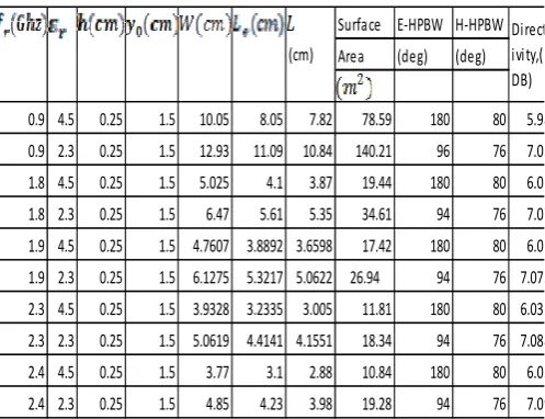
Table 1 Data Table For Rectangular Patch
Antenna
Table II Data Table For Circular Patch
Antenna
[image:4.595.318.561.63.199.2]Fig 1. Rectangular Resonant Freq=0.9Hz, dielectric=4.5, substrate height=0.25cm
Fig 2. Resonant Freq=0.9Hz, dielectric=4.5, substrate height=0.25cm
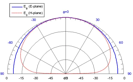
Fig 3.Rectangular MPA: E-H plane pattern: Resonant Freq=0.9Hz, dielectric=2.32, substrate height=0.25cm
Surface E‐HPBW H‐HPBW
Area (deg) (deg)
0.9 4.5 0.25 1.5 10.05 8.05 7.82 78.59 180 80 5.98
0.9 2.3 0.25 1.5 12.93 11.09 10.84 140.21 96 76 7.03
1.8 4.5 0.25 1.5 5.025 4.1 3.87 19.44 180 80 6.02
1.8 2.3 0.25 1.5 6.47 5.61 5.35 34.61 94 76 7.07
1.9 4.5 0.25 1.5 4.7607 3.8892 3.6598 17.42 180 80 6.02
1.9 2.3 0.25 1.5 6.1275 5.3217 5.0622 26.94 94 76 7.073
2.3 4.5 0.25 1.5 3.9328 3.2335 3.005 11.81 180 80 6.032 2.3 2.3 0.25 1.5 5.0619 4.4141 4.1551 18.34 94 76 7.088
2.4 4.5 0.25 1.5 3.77 3.1 2.88 10.84 180 80 6.03
2.4 2.3 0.25 1.5 4.85 4.23 3.98 19.28 94 76 7.09
(cm)
Direct ivity,( DB)
E‐
HPBW H‐
HPBW Directi vity, (deg) (deg) (DB) 0.9 4.5 0.25 1.5 4.52 4.606 44.59 180 84 6.041 0.9 2.3 0.25 1.5 6.23 6.417 61.53 96 80 7.248 1.8 4.5 0.25 1.5 2.23 2.304 21.99 180 84 6.043 1.8 2.3 0.25 1.5 3.05 3.212 30.15 96 80 7.253 1.9 4.5 0.25 1.5 2.107 2.183 13.95 180 84 6.043 1.9 2.3 0.25 1.5 2.888 3.044 26.19 96 80 7.254 2.3 4.5 0.25 1.5 1.732 1.804 9.423 180 84 6.044 2.3 2.3 0.25 1.5 2.367 2.516 17.6 96 80 7.257 2.4 4.5 0.25 1.5 1.66 1.73 16.36 180 84 6.044 2.4 2.3 0.25 1.5 2.26 2.41 22.35 96 80 7.257
(cm)
Surfac e
area
-45
-45 -30
-30 -15
-15 0
0
90 0 6030 30
60
=0 =90
330 120
300 150
270 180
dB
E- and H-plane Patterns of Rectangular Microstrip Antenna
dB E (E-plane)
E (H-plane)
-45
-45 -30
-30 -15
-15 0
0
90 60 30
=0
-30
-60
-90
dB
E- and H-plane Patterns of Circular Microstrip Antenna
dB E (E-plane)
E (H-plane)
-45
-45 -30
-30 -15
-15 0
0
90 0 6030 30
60
=0 =90
330 120
300 150
270 180
dB
E- and H-plane Patterns of Rectangular Microstrip Antenna
dB E (E-plane)
[image:4.595.325.538.291.430.2] [image:4.595.49.298.374.565.2] [image:4.595.312.553.487.639.2]Fig 4. Circular MPA: E-H plane pattern: Resonant Freq=0.9Hz, dielectric=2.32, substrate height=0.25cm
[image:5.595.319.543.60.196.2]Fig 5 Rectangular: E-H plane: Resonant Freq=1.8Hz, dielectric=4.5, substrate height=0.25cm
[image:5.595.67.290.62.199.2]Fig 6 Circular: E-H plane: Resonant Freq=1.8Hz, dielectric=4.5, substrate height=0.25cm
[image:5.595.60.289.281.412.2]Fig 7 Rectangular: E-H plane: Resonant Freq=2.4Hz, dielectric=2.32, substrate height= 0.25cm
Fig 8. E-H plane: Resonant Freq=2.4Hz, dielectric=2.32, substrate height= 0.25cm
VI RESULTS AND CONCLUSION
In this work, specific frequencies have been
chosen-0.9Ghz, 1.8 GHz, 1.9 GHz, 2.3 GHz and
2.4 GHz-these frequencies corresponds to that of
GSM, LTE and BLUETOOTH. These frequencies
are very important in designing antennas for
Mobile phones and Bluetooth-enabled devices.
Two types of materials, roger (with a relative
dielectrics of 4.5) and duroid (with a relative
dielectrics, of 2.32) have been used as substrate
.The tables shows how the choice of dielectric
constant affects different antenna parameters at
these four important frequencies, for a rectangular
and a circular Microstrip Patch antenna. A
common trend is noticed in this work - to obtain a
smaller patch antenna (in terms of size, amount of
-45-45 -30
-30 -15
-15 0
0
90 60 30
=0
-30
-60
-90
dB
E- and H-plane Patterns of Circular Microstrip Antenna
dB E
(E-plane) E
(H-plane)
-45
-45 -30
-30 -15
-15 0
0
90 0 6030 30
60
=0 =90
330 120
300 150
270 180
dB
E- and H-plane Patterns of Rectangular Microstrip Antenna
dB E (E-plane)
E (H-plane)
-45
-45 -30
-30 -15
-15 0
0
90 60 30
=0
-30
-60
-90
dB
E- and H-plane Patterns of Circular Microstrip Antenna
dB E (E-plane)
E (H-plane)
-45
-45 -30
-30 -15
-15 0
0
90 0 6030 30
60 =0
=90
330 120
300 150
270 180
dB
E- and H-plane Patterns of Rectangular Microstrip Antenna
dB E (E-plane)
E (H-plane)
-45
-45 -30
-30 -15
-15 0
0
90 60 30
=0
-30
-60
-90
dB
E- and H-plane Patterns of Circular Microstrip Antenna
dB E (E-plane)
[image:5.595.67.279.494.641.2]material used), a material of higher dielectrics (the
Rogers dielectric 4.5 gives an antenna of smaller
size than duroid the dielectric) needs to be used,
for both the rectangular and circular Microstrip
patch antenna. In this era of miniaturization,
incorporating a small antenna in a mobile phone
or any device is a desired quality. When compared
with each other, to obtain the same directivity, a
circular Microstrip Patch antenna will need less
size (material) than the corresponding rectangular
one at any particular frequency. For example,
from the table, to get a directivity
6
, at
frequency of 0.9 GHz using Rogers,
4.5
(for
a rectangular (5.98dB), we need a patch antenna
with material area of
78.59
while for a circular
patch operating at the same frequency, we need a
patch of material with area of
44.59
.This is a
significant result, both in material savings, size
conformity and aesthetics , as it shows that high
miniaturization can be achieved by using circular
Microstrip Patch than rectangular (in a ratio
1:2)
Directivity is a quantitative measure of an
antenna’s ability to concentrate radiated power per
unit solid angle in a particular direction; it is a
very important antenna parameter especially in
RADAR systems. Microstrip Patch antennas
generally have low directivity when compared to
dipoles and some other types of antenna due to
their relatively large High Power Bandwidth
(HPBW) both in the E and H planes. From the
tables and plots, the use of material with lower
dielectric constant improves the directivity, both
for circular a rectangular Microstrip patch (hence
at any frequency duroid gives a better result than
Roger).
In conclusion, this work has shown that circular
Microstrip
patch
antenna
gives
better
performance,
enhances
the
concept
of
miniaturization when compared to the rectangular
Microstrip Patch antenna
REFERENCES
[1]. Constantine A Balanis, “Antenna Theory, Analysis and Design 3rd Edition”, published by Wiley
[2] Lamont V.Blakes, Maurice W. Long. “Antenna Fundamental, Design, Measurement “. Scitech Publishing Inc.
[3]. John D Krauss, Ronald J Marhefka, “Antennas For All Application 3rd Edition.”
[4]. G D Bhatnagar,J S Saini, V K Saxena, L M Joshi “Design of broadband circular patch Microstrip patch antenna with diamond shape slot” .Indian Journal of Radio& Space Physics, Vol1 40,October 2011, pp 275-281.
[5]. Thomas Edling “Design of Circular Polarized dual band Patch Antenna”. Masters Thesis for Uppsala Universitet, Sweden.
[6]. Benjamin D. Braaten, Sayan Roy, Sanjay Nariyal, Masud Al Aziz, Neil F. Chamberlain, Irfan Irfanullah, Michael T. Reich, Dimitris E. Anagnostou. “A Self-Adapting Flexible (SELFLEX) Antenna Array for Changing Conformal Surface Applications” IEEE TRANSACTIONS ON ANTENNAS AND PROPAGATION, VOL. 61, NO. 2, FEBRUARY 2013
[7]. Benjamin Davis Braaten, “MODELING MULTIPLE PRINTED ANTENNAS EMBEDDED IN STRATIFIED
UNIAXIALANISOTROPIC DIELECTRICS”.A
Dissertation Submitted to the Graduate Faculty of the North Dakota State University of Agriculture and Applied Science [8]. Arun Singh Kirar, Veerendra Singh Jadaun, Pavan Kumar
Sharma” Design a Circular Microstrip Patch Antenna for Dual Band,” Department of Electronics, MITS, Gwalior , India International Journal of Electronics Communication and Computer Technology (IJECCT) Volume 3 Issue 2 ,March 2013.
[9]. C. VISHNU VARDHANA REDDY “DESIGN OF
LINEARLY POLARIZED RECTANGULAR
MICROSTRIP PATCH ANTENNA USING IE3D/PSOA” THESIS SUBMITTED IN PARTIAL FULFILLMENT OF THE REQUIREMENTS FOR THE DEGREE OF Bachelor of Technology in Electronics and Communication Engineering.
[10]. Binu Paul, S. Mridula, C. K. Aanandan , and P. Mohanan,”A NEW MICROSTRIP PATCH ANTENNA FOR MOBILE
COMMUNICATIONS AND BLUETOOTH
APPLICATIONS.”
[11]. Alak Majumder, “Rectangular Microstrip Patch Antenna Using Coaxial Probe Feeding Technique to Operate in S-Band” ,International Journal of Engineering Trends and Technology (IJETT), Volume 4 ,Issue 4, April 2013
[12]. MarufAhamed, Kishore Bhowmik, Md. Shahidulla, “Rectangular Microstrip Patch Antenna at 2GHZ on Different Dielectric Constant for Pervasive Wireless Communication “
[13]. Ahmed FatthiAlsager,” Design and Analysis of Microstrip Patch Antenna Arrays” University College of Borås School of Engineering.
[14]. Indrasen Singh, Dr. V.S. Tripathi .Indrasen Singh et al; “Micro strip Patch Antenna and its Applications: a Survey,” Int. J. Comp. Tech. Appl., Vol 2 (5), 1595-1599.
[15]. Salman Haider Lindsay Young,” Microstrip Patch Antennas for Broadband Indoor Wireless Systems”, Faculty of Engineering, University of Auckland