Abstract—In the paper new structure elements have been developed and implemented in the already-existing TRT thermo-dynamic tyre model. The updated model aims to provide a complete tool to study and understand all the phenomena concerning the tyre in thermal transient conditions, since all the elements constituting its structure are finally modelled. The computational cost, connected to a more complex model to manage, was decreased by simplifying the mesh of the previous version of the model and, thus, by reducing the state vector length.
Index Terms—Tyre structure implementations, tyre thermodynamics modelling, tyre temperature real-time estimation
I. INTRODUCTION
he characterization of the tyres is an essential issue for the formulation of vehicle dynamics models, since the tyres allow the interaction with the road and are interested by the fundamental slip related phenomena [1][2].
Nowadays everyone playing a role in automotive sector is looking for the optimal solution in order to model and to understand the tyres behaviour in both experimental and simulation environments. The ability to predict the interior temperature distribution, and thus the grip behaviour of the tyre [3], is fundamental in terms of the vehicle handling improvement and of the asset optimization according to highly variable outdoor testing conditions [4].
The new implementations to the already existing TRT thermo-dynamic model have a key purpose: to add new structure elements and, thus, to enhance and optimize the physical response, but not at the expense of the real-time simulation.
II. TRT-THERMO RACING TYRE MODEL
The model, called Thermo Racing Tyre (TRT) [5] was developed in collaboration between the Department of Industrial Engineering of the University of Naples Federico II and a top ranking motorsport team.
The model is three-dimensional and takes into account of the following thermo-dynamic phenomena:
heat generation due to:
tire-road tangential interaction, known as “Friction Power”;
effect of tyre cyclic deformation during the rolling, known as “SEL” (strain energy loss);
Manuscript received March 21, 2015.
Flavio Farroni is with Dipartimento di Ingegneria Industriale, Università degli Studi di Napoli Federico II, via Claudio n. 21 80125 Napoli Italy (e-mail: [email protected]).
Aleksandr Sakhnevych is with Dipartimento di Ingegneria Industriale, Università degli Studi di Napoli Federico II, via Claudio n. 21 80125 Napoli Italy (e-mail: [email protected]).
heat exchange with the external environment due to: thermal conduction between the tread and the road; forced convection of the surface layer with the
outside air;
natural convection of the inner liner with the inner air;
heat conduction between the tyre layers due to the temperature gradient.
A. Tyre modelling
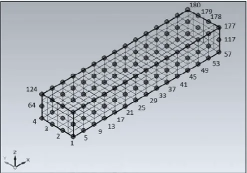
As in the original version, the tyre, modelled as slick, is considered as unrolled in the circumferential direction along x-axis, lacking of sidewalls and grooves (Fig. 1). Its parallelepiped shape is constituted by three layers in the radial direction z, indicated as surface (outer surface of the tyre structure), bulk (intermediate layer), and inner liner (inner coating).
Each layer is discretized by means of a grid, whose nodes represent the points in which the temperature can be determined in real time. To the generic i-th node a parallelepiped volume Vi is associated, equal to
∆ ∙ ∆ ∙ ∆ , (1)
in which Δx and Δy are respectively the dimensions along the longitudinal-circumferential and the transversal-wide
directions, while the quantity ΔZm,i represents the thickness of
a node’s mass associated to i-th layer along the radial one. With special regard to the tyre’s structure, in which visco-Francesco Timpone is with Dipartimento di Ingegneria Industriale, Università degli Studi di Napoli Federico II, via Claudio n. 21 80125 Napoli Italy (corresponding author: phone: +39 081 76 83263; fax: +39 081 2394165; e-mail: [email protected])
An Evolved Version of Thermo Racing Tyre
for Real Time Applications
T
[image:1.595.306.554.459.632.2]Flavio Farroni, Aleksandr Sakhnevych, Francesco Timpone
elastic vulcanized polymers and fillers mainly constitute the tread and the carcass includes also reinforcements, two zones of homogeneous material have been identified and characterized by the following physical parameters along the radial direction:
density ρ specific heat cv
thermal conductivity K
where, in particular, the variability of the last two terms with temperature is taken into account. Thus, each node has a mass expressed as follows:
∙ ∙ (2)
where the dimensionless C coefficient depends on its position in the grid.
B. Base hypotheses
With the aim of modelling heat dynamics and tyre layers temperature distribution, the following assumptions have been adopted:
road: schematized as a geometric plane without irregularities, isotropic and homogeneous in all its characteristics, whose surface temperature is equal to Tr
contact area: assumed to be rectangular, whose dimensions are the width W of the tread and the length La depending on the tyre radial stiffness and
on the normal load applied
camber angle: assumed equal to zero
linear variation of the contact patch extension related to the value reached under the application of the static load by means of an appropriate set of coefficients
motionless tyre with variable boundary conditions neglection of the radiation heat transfer mechanism C. Thermodynamic model
The developed thermodynamic tyre model is based on the use of the diffusion equation of Fourier applied to a three-dimensional domain.
The complexity of the transient thermo-dynamical phenomena under study and the degree of accuracy required implies the dependence of the thermodynamic quantities, and in particular of the thermal conductivity, on the temperature. Furthermore, the non-homogeneity of the tyre has made it necessary to consider the variation of the above parameters also along the thickness.
Therefore, the Fourier equation takes the following formulation [6]:
∙
1 ∙
∙ , ∙ , ∙
, ∙
(3)
Writing the balance equations for each generic node needs the modelling of heat generation and of heat exchanges with the external environment.
D. Heat exchange
The heat exchange between the tyre and the external environment, remembering that the radiation mechanism is neglected by hypothesis, it can be classified as follows:
Heat exchange with the road
The thermal exchange between the tread and the asphalt has been modelled through Newton's formula [7], schematizing the whole phenomenon by means of an appropriate coefficient of heat exchange. The term for such exchanges, for the generic -th node will be equal to:
∙ ∙ ∆ ∙ ∆ (4)
where:
is the convective heat transfer coefficient, estimated for the track testing conditions
∙ ;
is the track temperature . Heat exchange with the outside/inside air
The whole mechanism of the heat transfer between a generic surface and a moving fluid at different temperatures is described by natural and forced convection equations. The convection heat transfer is expressed by Newton’s law of cooling, as before:
∙ ∙ ∆ ∙ ∆ (5)
Therefore, the heat exchange with the outside air is modelled by the mechanism of forced convection, occurring when there is relative motion between the car and the air, and by natural convection, when such motion is absent.
Natural convection is also employed to characterize the heat transfer of the inner liner with the inflating gas. The determination of the convection coefficient , both forced and natural , is based on the classical approach of the dimensionless analysis [7, 8].
Supposing the tyre invested by the air similarly to a cylinder invested transversely from an air flux, the forced convection coefficient is provided by the following formulation [8, 9]:
∙ 0.0239 ∙ ∙
.
(6)
in which:
∙ is air conductivity, evaluated at an
average temperature between the effective air one and outer tyre surface one;
is considered to be equal to the forward speed of the vehicle (air speed is supposed to be zero);
is the kinematic viscosity of air, empirically obtained as:
5 ∙ 10 ∙ , 10
∙ ,
0.0008 ∙ , 0.135 ∙ 10
(7)
is the characteristic length of the heat transfer surface;
, is the arithmetic mean between the
The values of evaluated with the above approach are close to those obtained by means of CFD simulations [10].
The natural convection coefficient , however, can be expressed as:
∙
(8)
in which, for this case:
0.53 ∙ . ∙ . (9)
E. Heat generation
As concerns the tyre, the heat is generated in two different ways: for friction phenomena arising at the interface with the asphalt and because of stress-deformation cycles to which the entire mass is subjected during the exercise (SEL).
Friction power
The first heat generation is connected with the thermal power produced at tyre-road interface because of interaction; in particular, it is due to the tangential stresses that, in the sliding zone of the contact patch, do work dissipated in heat. Friction power can be associated directly to the nodes involved in the contact with the ground, and it is calculated as referred to global values of force and sliding velocity, assumed to be equal in the whole contact patch:
∙ ∙
(10)
where a part of this thermal power is transferred to the tyre and the remaining to the asphalt.
Since Fx and Fy are global forces between tyre and
road, and it is not known the contribution of each node to these interaction forces, heat generated by means of friction power mechanism transferred to the tyre has been equally distributed to all the nodes in contact with the ground. The model allows uneven local heat distributions as soon as local stresses and velocities distributions are known.
Strain Energy Loss
The energy dissipated by the tyre QSEL because of
cyclic deformations is due to a superposition of several phenomena: intra-plies friction, friction inside singular plies, nonlinear visco-elastic behaviour of all rubbery components, etc.
During the rolling, the entire tyre is subjected to the cyclic deformations with a frequency corresponding to the tyre rotational speed. During the motion, portions of tyre, entering in sequence in the contact area, are subjected to deformations, which cause energy loss and then heat dissipation.
In the model, the amount of heat generated by deformation (SEL) is estimated through experimental tests carried out deforming cyclically the tyre in three directions (radial, longitudinal and lateral) [11]. Estimated energies do not exactly coincide with the ones dissipated in the actual operative conditions, as the deformation mechanism is different; it is however possible to identify a correlation between them on the basis of coefficients estimated from real data telemetry. F. Contact area calculation
The size and the shape of the contact area are function of
the vertical load Fz, of the inner pressure pin and of the
camber γ and toe φ angles.
The contact area is assumed to be rectangular in shape with constant width W, equal to the tread’s one, and length La,
variable with the above mentioned parameters, except the toe angle. The number of nodes in contact is then calculated from the effective area of contact, which is obtained, taking into account actual vertical load and inflating pressure, on the basis of the results provided by FEM simulations and pressure sensitive films [12].
G. Constitutive equations
The power balance equations, on heat transfers, are written for each elementary mass associated to each node, and differ in relation to their position inside the grid.
The heat conductivity between the surface and the bulk layers is indicated with k1, while with k2 is indicated the heat
conductivity associated to the exchange between the bulk and the inner liner layer.
[image:3.595.339.521.353.509.2]In the model, the tyre is considered motionless and the boundary conditions rotating around it to take into account the fact that elements belonging to the surface layer will be affected alternatively by the boundary conditions corresponding to the contact with the road and to the forced convective exchange with the external air.
[image:3.595.335.515.572.727.2]Fig. 3. Thermal powers exchanged in all directions for the control volume associated with node 2, assumed in contact with the external air. Note the absence of the generative term and the presence of the term identifying the exchange with the outside air, characterized by hforc coefficient.
As an example, heat balance equations for the surface node
2 are graphically reported in figures 2 and 3, recalling that, for the performed discretization, the nodes adjacent to node 2
are 6 and 58 along the direction, 1 and 3 along the y direction and 62 along the z direction.
The previous images show the thermal powers, exchanged in all directions respectively for the two cases, only for node 2: road contact (Fig. 2) and contact with the external air (Fig. 3).
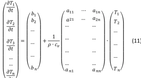
Finally, the matrix equation at the basis of the model is:
… …
…
…
…
1 ∙
⋯
… …
…
…
…
…
…
…
… ∙
…
…
…
(11)
in which is the generic coefficient, relative to the energy balance equation of the node , that multiplies the -th node temperature, while is the generic coefficient not multiplying nodes temperatures.
Generally, to properly operate in order to provide the tyre temperature distribution, the model requires the following input data: normal, longitudinal and lateral tyre-road interaction forces, longitudinal and lateral sliding speeds, forward speed at the wheel centre, air and road temperature. The structural characteristics and the thermal properties of the tyre and the thermal conductivity of the track are also required.
Some of these data result from the telemetry measurements available for different tracks and are preliminarily analysed in order to check their reliability; others, such as in particular the ones related to structural and thermal characteristics of the tyre, are estimated on the basis of measurements and tests conducted on the tyres [13].
In addition to surface, bulk and inner liner temperature distributions, the model also provides the thermal flows involving the tyre, such as the flow due to the external air cooling, the one due to the cooling with the road, the one with the inflation air as well as the flows due to friction, hysteresis and exchanges between the different layers.
III. NEWTRT IMPLEMENTATIONS
In the latest versions, Thermo Racing Tyre has been simplified in order to reduce the number of equations to solve and so to decrease the computation burden. The changes concerned the substitution of the node grid on the internal layers (bulk and inner liner) with a singular node configuration.
The performance gain, obtained with the above-mentioned simplification, has been employed to run the iterations concerning the sidewalls nodes. These new elements, constituting the tyre structure, have been introduced in the model to estimate more accurately the temperature of the inner liner, since the latter is actively involved in the convective heat exchange with the external and the internal airflow [14].
A. TRT – Simplified mesh
The classic TRT was a discrete three-dimensional model, discretized by means of a grid, whose nodes represented the points in which the temperature was determined instant by instant, as shown in figure 1.
The number of nodes of the grid was given by the product
( ∙ ∙ ) where represented the number
of nodes along the direction, the number of nodes along the direction and was the number of nodes along the direction. Nodes enumeration had been carried out starting from the first layer in contact with the road, proceeding transversely.
Over time, TRT’s three-layer configuration was simplified as following (Fig. 4):
Surface (grid of nodes in blue): outer surface of the tyre, made up of a grid of nodes, whose number is given by the product ( )
Bulk (parallelepiped in black): intermediate layer modelled as a singular node;
Inner liner (parallelepiped in magenta): inner layer modelled as a singular node.
Considering the model within a thermo-mechanical chain, regarding respectively the bulk and inner layers, a detailed temperature distribution of these zones is unnecessary anymore because of their thermal inertias. This consideration allowed to simplify the discretization, reducing respectively the bulk and the inner layers to single nodes. With this, the computational burden is decreased and consequently TRT can be used in real time applications [15] without any difficulties.
In fact, the number of state variables and therefore of equations (11) has been reduced from n to (n/3+2). The above simplification was made preserving the heat transfers between the layers, whose inertial and thermal material properties, as density, conductivity and specific heat, were respectively attributed to singular nodes.
To take into account the simplification adopted, the bulk and inner liner nodes only allow the heat exchange along the radial direction of the tyre; therefore the tangential heat transfers inside the single interior tiers have been supposed absent. In particular, since the bulk and the inner nodes are assumed to have the heat exchange area along the radial direction equal to the rectangle, whose dimensions coincide with tyre circumferential length and width, the heat balance equations can be respectively written as:
∙ ∙ ∙ ∙ ∆ , ∙
∆ ∆
,
∆ ∙
∙ ∙
∆ ∙ ,
∙ ∙
(12)
[image:4.595.50.283.172.301.2]
∙ ∙ ∙ ∙ ∆ , ∙ ∆
∆ ∙
∙ ∙ ,
∆ ∙
∙ ∙
(13)
where Tsurf,avg is the mean temperature value of the entire
surface layer. The above-mentioned equations are therefore developed in order to write a complete set of normal-form equations (11), as follows:
∆ ∆
1
∙ ∙ ∙ ∙ ∆ ,
,
∆ , ∙ ∆
∙ ,
∆ , ∙ ∆
∙ ,
(14)
∆ ∆
1
∙ ∙ ∙ ∙ ∆ , ∆ ,
∙ ,
∆ , ∙ ∆
∙
(15)
B. TRT – Sidewalls implementation
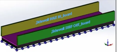
To estimate more accurately the temperature distribution even of the deepest tyre layers, usually not easily measurable on-line, an innovative structure configuration was adopted. The evolved tyre structure includes the presence of the sidewalls, actively involved in the convective heat exchanges with the external airflow and the inner gas fluid threads inside the wheel. Inside the chamber, the tyre sidewalls thermally interact with the inner gas, that is in its turn involved in the heat convective exchange with the inner liner.
As shown in figure 5, the TRT tyre structure with sidewalls implementation is still considered unrolled. The sidewalls have been discretised as two parallelepiped shaped single node layers. In this way their nodes, called surface (in green) and bulk (in yellow), for a right tyre, are respectively in contact with the external air flux and with the inner gas contained inside the wheel chamber. It is also necessary to highlight that the same sidewall nodes are diversified in in_board and out_board, regarding their position towards the vertical longitudinal plane of symmetry of the vehicle (in_board and out_board sidewalls are correspondingly the nearest and the farthest ones); therefore the thermal convective powers, respectively investing the sides of the tyre, will be different.
The sidewalls take in account both the conductive and the
convective heat exchanges. In particular, as regards the external sidewall nodes, the convective exchange rate with the external airflow is obtained from the heat transfer area ASide,calculated knowing the CAD of the tyre; meanwhile, the
internal sidewall nodes are involved in the convective heat exchange with the inner gas fluid threads. The heat balance equations related to respectively the sidewall layer’s external and internal nodes are:
,
,
, ,
, ,
(16)
,
,
, ,
, ,
(17)
The (16) and (17) are further developed as follows:
, 1
∙ ∙ , , ,
,
∙ , ,
∙ , ,
(18)
, 1
∙ ∙ , , ,
,
∙ , ,
∙ , ,
(19)
IV. RESULTS
First of all, a comparison between the fully discretized version of TRT and the mononodes one is illustrated. Other things being equal, the above models have negligible differences between temperature trends for all the tyre layers, as shown in figure 6.
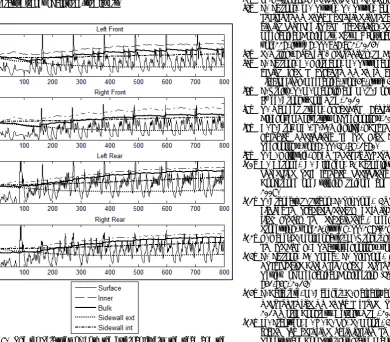
In figure 7, the temperature trends of all the tyre layers of the new-modelled TRT with the sidewalls implementation for all the four wheels, are illustrated (it must be highlighted that in the above figures the temperature values are dimensionless because of confidentiality agreements).
[image:5.595.42.290.460.571.2]As expected, the mean temperature values of respectively the internal (tread bulk/inner and sidewall bulk) and the external (tread surface and sidewall surface) tyre layers are fairly close. The difference in the thermal shapes of the external layers is due to their position inside the tyre structure: the tread layers, especially the surface one, are subjected to the instant thermal powers generated by the tyre/road interaction; meanwhile a slow temperature trend induced concurrently by the rolling fatigue effect and by the convective heat exchanges characterizes the sidewalls dynamics. That is why, the internal tyre strata seem to have a slow temperature ascent during the rolling motion of the wheel, while the tread surface layer is characterized by an oscillating profile.
V. CONCLUSION
The adoption of a new simplified tyre configuration and the implementation of an opportune mesh allowed to obtain a complete tyre temperature distribution in all the tyre working conditions, being able to fit the response of the model to the telemetry data, minimizing moreover the computer resources expended. In this way, the updated model aims to provide a tool useful to study and understand all the thermal phenomena concerning the tyre during its interaction with both the external environment and the internal chamber. In fact, the factors like the inflating gas pressure, since its influence on the tyre rolling fatigue, can be optimized with the above instrument.
It has to be highlighted that, to be used in a predictive manner, the model needs an initial tuning phase to be carried out only once for each season, because of changes in car setup and tyres construction. Once developed through this operation, known all inputs, the results obtained are in good agreement with the telemetry data, with reference to the various operating conditions of the different tracks.
REFERENCES
[1] H. B. Pacejka, Tyre and Vehicle Dynamics, Butterworth-Heinemann, 2006.
[2] M. Guiggiani, The Science of Vehicle Dynamics, Springer, 2014. [3] F. Farroni, M. Russo, R. Russo, and F. Timpone, “A physical–
analytical model for a real-time local grip estimation of tyre rubber in sliding contact with road asperities”, Proceedings of the Institution of Mechanical Engineers, Part D: Journal of Automobile Engineering, vol. 228, issue 8, pp. 958-972, 2014.
[4] P. Wright, Formula 1 Technology, SAE, 2001.
[5] F. Farroni, D. Giordano, M. Russo and F. Timpone, “TRT: thermo racing tyre a physical model to predict the tyre temperature distribution”,Meccanica, vol. 49, issue 3, pp. 707-723, 2014.
[6] F. Kreith, R. M. Manglik and M. S. Bohn, Principles of Heat Transfer. 6th ed. Brooks/Cole USA, 2010
[7] R. Van der Steen, “Tyre/Road Friction Modeling”, Ph.D. Thesis, Eindhoven University of Technology, 2007.
[8] A. L. Brown A., L. E. Wickliffe, “Parametric Study of Convective Heat Transfer Coefficients at the Tire Surface” Tire Science and Technology, vol. 8, pp. 37-67, 1980.
[9] T. D. Gillespie, “Fundamentals of Vehicle Dynamics”, SAE, 1992. [10] D. Derome, B. Blocken, J. Carmeliet, “Determination of surface
convective heat transfer coefficients by CFD”, 11th Canadian Conference on Building Science and Technology, Banff, Alberta, 2007.
[11] R. Brancati, S. Strano, F. Timpone, "An analytical model of dissipated viscous and hysteretic energy due to interaction forces in a pneumatic tire: Theory and experiments", Mechanical Systems and Signal Processing, vol. 25, issue 7, pp. 2785–2795, 2011.
[12] G. Gabel, P. Moldenhauer, M. Kroger, “Local Effects Between the Tyre and the Road”, ATZautotechnology, vol.8, issue 4, pp. 48-53, 2008. [13] F. Farroni, E. Rocca, F. Timpone, “A Full Scale Test Rig to
Characterize Pneumatic Tyre Mechanical Behaviour”, International Review of Mechanical Engineering (I.RE.M.E.), vol. 7, issue 5, pp. 841-847, 2013.
[14] F. Calabrese, M. Baecker, C. Galbally and A. Gallrein, “A full thermo-mechanical tire model for advanced handling applications”, SAE 2015 World Congress, Detroit, USA, 2015.
[15] M. Frantzen, A. H. C. Ng, P. Moore, A simulation-based scheduling system for real-time optimization and decision making support”, Robotics and Computer-Integrated Manufacturing, vol. 27, issue 4, pp. 696-705, August 2011.
[image:6.595.48.292.50.336.2] [image:6.595.62.453.359.701.2]