Finite element method simulations of heat flow in fixed bed solar water splitting redox
reactors
B. Bulfin∗, B. E. Murphy, O. L¨ubben, S. A. Krasnikov, I. V. Shvets
School of Physics, Trinity College Dublin, Dublin 2, Ireland
Abstract
An improved design for radiation absorption and heat flow into materials with low thermal conductivity is demonstrated. The design was developed for application in fixed bed two step solar water splitting redox reactors. The fixed bed was assumed to be made from porous ceramic. The low thermal conductivity of the porous ceramic redox material is compensated for by changing the profile of the fixed bed. The profiling used was wedges cut into the material which allows concentrated solar radiation to be incident on a larger area of redox material than a flat monolith design. The design is demonstrated to efficiently transfer heat to the bulk and greatly reduce re-radiation. For a wedge 9 cm in depth and 1.6cm wide at the opening, heated with 500 Wm2s−1incident radiation for 300 seconds approximately double the amount of radiation is absorbed. The effects of thermal conductivity, emissivity and scaling of the design were investigated. The radiation absorption performance improved when scaled up. The improvement of the design over a flat plain increases for lower emissivity. The improvement provided by the wedge design was found to decrease for increasing thermal conductivity, and eventually for high conductivity values it reduced performance. Using this method a larger amount of material with low thermal conductivity can be heated with the same power input and reduced radiation losses. Finally a concentrated solar cavity reactor based on the design is proposed.
Keywords: Hydrogen production, Redox Reactors, Water Splitting, Efficiency, Heat Flow
1. Introduction
Splitting water to produce hydrogen using renewable energy sources is an attractive pathway for renewable fuels. A thermo-chemical water splitting cycle can be driven using concentrated solar power as the heat input [1, 2]. Thermochemical water splitting uses high temperature process heat to drive the en-dothermic water splitting reaction. Direct thermal water split-ting is possible, but impractical as the process temperatures are very high (≈2500 K for partial decomposition). This decompo-sition leads to a high temperature mixture of gases which must be separated [3].
Two-step water splitting cycles proceed at lower tempera-tures, and hydrogen and oxygen are given offat different stages of the reaction, which removes the need for separating a mix-ture of gases[4]. Many two-step cycles have been proposed us-ing metal oxides as the redox material [5]. In these cycles the process heat is used to reduce or partially reduce a metal oxide, releasing oxygen. The reduced oxide is then reacted with water to produce hydrogen.
The process can be described by the following chemical re-actions
MOx−→MOx−δ+ δ
2O2 (1)
MOx−δ+δH2O−→MOx+δH2 (2)
∗Corresponding author. Telephone:+35318963139 email: [email protected]
The first reaction is endothermic and requires high tempera-ture process heat to proceed (>1400◦C). The second reaction
is slightly exothermic and proceeds at a lower temperatures (≈900◦C).
Thermodynamically zinc(II) oxide is one of the most promis-ing materials [7]. However in practice the cycle has some com-plications. ZnO is volatile and sublimates when decomposing. This results in a hot mixture of zinc and oxygen gases which must be quenched to separate [8]. For this reason other cycles are sought with more simple separation processes.
The cycles we are concerned with here are those in which the redox material remains in the solid phase, but releases part of its oxygen. These cycles offer the simplest process as they can be used in a fixed bed reactor. Many promising materials have been identified including supported NiFe2O4 and CeO2
[9, 10, 11, 12]. Both of these compounds are partially reduced releasing some of their oxygen. Since they do not change phase, the oxygen is released through the surface, and the water split-ting reaction takes place at the surface. In order to increase their yield the surface area must be maximised. To do this, the materials, either supported or unsupported, can be formed into porous monoliths [13, 14]. These monoliths form the fixed bed of the reactor.
can lead to large losses. For this reason, rapid reaction rates are preferable for the reduction step. The ratio of the amount of re-dox material to the power is also very important. If only a small amount of redox material can be heated by the concentrated so-lar radiation, then the chemical yield will be low compared to the amount of re-radiated heat. This presents a problem for fixed bed reactors made from porous ceramic monoliths.
The ceramic materials have low thermal conductivity, which is further reduced by the porosity [15]. This affects the heating rate of the fixed bed. The surface may be rapidly heated while the nearby interior, may take a long time to reach the reaction temperature. As the surface is heated rapidly, the fixed bed will re-radiate a lot of heat while the interior of the monolith is still heating up. This can result in large re-radiation energy loses, which greatly reduce the efficiency. The large temperature gra-dients can also degrade the materials due to thermal shock. It has been experimentally noted that if a large bulk porous mono-lith is used, the heating rate in the interior is very slow [16], while the surface will be rapidly heated and begin to re-radiate the received power. In order to compensate for this, thin layers of reactive material can be used. However, this means that only a small amount of redox material can be used and it will have a large re-radiating area.
Here we discuss a method of profiling the ceramic monoliths to reduce re-radiation and greatly increase the amount of oxide which can be cycled with a given power input. The oxide is also heated more uniformly which will reduce thermal shock degradation.
2. Design
The concept of the design considered is rather similar to that of a cavity. The geometry considered in this study is a block of redox material with wedges cut into the bulk material as seen in Fig. 1. Concentrated solar radiation then shines onto the wedges. This reduces the intensity received at the surface but to a certain extent traps the radiation. Most of the re-radiated heat is incident on the opposite surface. The tips of the wedges can potentially re-radiate a large amount of heat. However, the thermal conductivity of the porous ceramics is very low, and heat is not conducted from the interior of the ceramic to the tips of the wedges at a large rate, so the amount of heat which can be lost due to radiation from the tips is limited by the low transfer of heat from the interior.
The simulations of the design initially concentrate on an infi-nite flat plane with and without the wedges, in order to demon-strates the heat flow. A practical cavity receiver design is then discussed, which offers high radiation capture efficiency and very good heat flow into the fixed bed.
3. Modeling
All heat flow simulations were conducted using the Finite Element Method (FEM) [17]. The simulation solves the heat flow equation (Eqn. 3) over the constructed domains.
CpρδT
[image:2.595.340.522.78.356.2]δt −k4T =Q (3)
Figure 1: A cross section of the ceramic profile, whereαis the acceptance angle for radiation in the plane of the page and L is the periodicity. The heat flow equations are symmetric about the parallel planes perpendicular to the page, indicated by the solid vertical lines.
WhereT is the temperature,Cp is the specific heat, ρ is the
density,kis the thermal conductivity andQis a heat source or sink term. In many reactor designs a method for reducing the oxygen partial pressure is used to stop the back reaction. This could involve placing the oxide in a purge gas or a vacuum. In this study we have considered the simple case of a vacuum. Now the only type of heat transfer at the boundaries is radiation from surface to surface or surface to ambient. The equations for heat flow at the boundaries are
ˆ
n•k∇T =q0+σ(Ta4−T
4) (4)
ˆ
n•k∇T =q0+(G−σT4) (5)
Equation 4 is the case where the surface is radiating to ambi-ent and 5 is the case where there is surface to surface as well as surface to ambient radiation. Here ˆnis the unit normal vector to the surface,q0is the surface heat source (concentrated solar
radiation), is the emissivity of the surface,Tais the ambient
temperature andGis the surface irradiation (radiation received from other surfaces and ambient). The value ofGfor a partic-ular surface element is the sum of the radiation received by all of the other surface elements and the ambient. For example, for theithsurface element,Giwould be of the form
Gi= j
X
i,j
FjiijAjσT4j +FaAaiTa4 (6)
FjiandFaare the view factors. The view factor is the fraction
i. They depend on the solid angle surface jcovers with respect to surfacei, and the difference in angle between the line joining the surfaces and j’s normal vector. AjandAa are the areas of
the jth element and of the ambient. The sum for the surface to surface elements is over jfor j , ito avoid self radiation.
To calculate the view factors in the simulations the hemicube method was used [18].
The above equations form the basis for the model. The sim-ulations were mainly conducted with a triangular mesh of finite elements in two dimensions (2D). The 2D simulations assume that the 2D profile extends to infinity, removing heat flow in that direction. The solution was linear between elements and computed using an iterative method.
4. Results
4.1. Infinite Array of Wedges
The initial simulations were carried out for an infinite flat plane with no additional measures to stop re-radiation. The ac-ceptance angle in the plane of the page is the angle of the wedge
α, as seen in Fig. 1. In the plane perpendicular to the page ra-diation can be accepted from all directions.
The ceramic was modelled to have the heat capacity and den-sity of 70% porous CeO2 [19]. The thermal conductivity of
CeO2and NiFe2O4 ceramics is very low, and when porosity is
[image:3.595.319.542.354.523.2]introduced it can more than half the thermal conductivity. We use an initial thermal conductivity of 2.5 Wm−2K−1 in the ex-ample below.
Figure 2: Temperature profiles for (a) the wedge design, and (b) a solid plane, after 300 seconds of heating from initial temperature of 300 K
In Fig. 2 we see the plane with wedges analysed alongside a solid plane of the same material. The total thickness is 15 cm,
the wedge cut is 9 cm in depth and 1.6 cm wide at the open-ing. For simplicity, the material surfaces are assumed to radi-ate as black bodies (=1) to an ambient temperature of 300 K. A power of 500 kW/m2 is received by both surfaces, which is
roughly 500 suns of concentration. The wedge receives much less heat per square metre of surface area however at a value of approximately 44 kW/m2, due to the tilt of the receiving surface
with respect to the radiation. As the wedge system is symmet-ric about the planes perpendicular to the page and bisecting the wedges at their tips, the solution will also be symmetric about these planes. For this reason they can be set to be thermally in-sulating forming a periodic boundary condition. The boundary at the back is also set to insulation as the heat lost here is negli-gible compared to the heat lost through the irradiated surfaces. This can be seen by the low temperature at the back surfaces even after 300 seconds of heating.
[image:3.595.65.254.446.698.2]An immediate observation is that a much larger volume of ceramic is heated to high temperature in the wedge case. This is an excellent improvement as the chemical yield for the oxygen releasing step is directly proportional to the amount of material which is heated, which should increase the efficiency.
Figure 3: The fraction of the total power received at the surfaces which is not re-radiated by the wedge and block vs. time
In Fig. 3 the area below each curve is the fraction of the total energy supplied which is absorbed and the area above is the energy re-radiated. From this we can see that as time pro-ceeds the amount of heat re-radiated by the wedge is far less than that re-radiated by the block. At 300 seconds, the tem-perature profiles are those shown in Fig. 2. The maximum temperature is reached in the interior of the wedges due to the re-radiation being trapped. The tips of the wedges are at rela-tively low temperature (≈1370 K) as compared to the surface of the solid plane(≈1670 K). This accounts for the lower amount of heat being re-radiated by the plane with the wedges cut.
4.2. Effects of thermal conductivity, emissivity and scaling
above analysis for different values of thermal conductivity, emissivity and scaling with an input power of 500 kW/m2.
(a)
(b)
[image:4.595.45.277.123.650.2](c)
Figure 4:(a):The fraction of the total power received at the surfaces which is not re-radiated for different values of thermal conductivity. The solid lines are for the wedge and the doshed lines are the block. The dimensions of the wedge were those of Fig. 2. (b):The fraction of total power absorbed by the wedge and block for three different vaues of emissivity, where the triangular markers indicate the wedges and square markers indicate the block. (c):The fraction of the total power received at the surfaces which is not re-radiated for different depth wedges with the same acceptance angle.
From Fig. 4 (a) we can see that as the thermal
conductiv-ity increases the amount of heat re-radiated decreases. For the block it decreases at a faster rate. For high values of k>25 W m−2 K−1 the wedge set up begins to re-radiate more than the block. At high thermal conductivities the solid block is able to carry away the heat faster and the surface does not heat up as quickly. Therefore this method of improving radiation absorp-tion is limited to the case of redox materials with low thermal conductivity.
At an intensity of 250 kW/m2the solid block outperforms the wedge when k>20 Wm2K−1. This lower threshold is due to the fact that the block needs to conduct less heat away from its sur-face. However, when the power is increased, the wedge design outperforms the block for a greater range of thermal conductiv-ities.
Intuitively this makes sense, the tips of the wedges can re-radiate a lot of heat, but if the thermal conductivity is low the power being supplied into the wedges cannot be conducted back to the tips. The wedge traps heat in the interior as most of the radiation is exchanged between the surfaces. The low thermal conductivity stops the heat from flowing to the highly radiating tips of the wedges and the lower the thermal conductivity the greater the improvement provided by the wedge system.
The affect of surface emissivity was also investigated. Fig. 4 (b) shows the fraction of power absorbed for three values of emissivity. The emissivity was constant over all frequencies. We can see that the block suffers badly with its initial power absorption scaling with the value of the emissivity. However in the wedge case the efficiency is not greatly decreased. Scat-tered light in the wedge case is likely to be incident on another portion of the wedge. Multiple scatterings result in much of the incident radiation being absorbed. This is a good sign as we would not expect the ceramic materials to act like ideal black bodies.
Finally the relationship between the scale of the wedges and the power absorption was examined. The depth of the wedge cut was varied between 1.125 cm and 18cm with the accep-tance angle kept constant atα =10.2◦. Fig. 4 (c) shows that smaller scale wedges approach the performance of the block, as expected. However, for larger scale wedges, the radiation cap-ture is further improved, and a larger amount of oxide is heated to the reaction temperature. This implies that implementation of this design in a large scale reactor could be feasible.
To get an idea of how this would affect the efficiency of a re-duction reaction we can couple the heat flow equations to reac-tion kinetics and check the reacreac-tion efficiency. Using an Arrhe-nius rate equation made to match experimental decomposition of powdered CeO2 we can compare the reaction performance
of the wedge to that of the block.
4.3. Heat flow coupled to Arrhenius rate equation
Using data extracted from an experiment in which CeO2
powder was decomposed in a vacuum, we can couple a rate law to our heat equations to evaluate potential performance of the wedge shaped reactor bed. Our decomposition reaction is
CeO2−→CeO2−δ+δ
In the experiments a small amount of CeO2nano-powder was
rapidly heated in a vacuum using a focused Xenon lamp. The temperature and pressure were recorded and from this an Ar-rhenius rate equation was made to match the results. This isnot an accurate representation of how the material would cycle if sintered into a porous monolith. The material was a nano pow-der with particle size less than 25 nm and thus had very high surface to volume ratio. The reactivity of a porous monolith would be lower. It is however useful to illustrate the potential for improvement in efficiency due to the wedge design.
The Arrhenius rate equations [20] used were of the form
d[Oox]
dt =k1[Oox]−k2[Ogas] (8)
kx=Axe−
Ex
RT (9)
where [Oox] and [Ogas] are the concentrations of removable
oxygen in the oxide and oxygen gas in the reaction chamber re-spectively. AxandExare the frequency factors and activation
energies which were varied to get a good match to the experi-ment. Only a small back reaction term was included as in this case we assume that the vacuum is being maintained.
The reaction consumes heat so we now have a heat sink term in the interior. The heat sink takes the form
Q=−d[Oox]
dt ∗∆H (10)
where∆His the change in enthalpy of the reaction. The value of ∆H varies from 963 kJ/molO2 to 770 kJ/molO2 asδis var-ied from 0 to 0.2 [21]. For simplicity, the weighted average of around 800 kJ/molO2 was used. The maximum δin these simulations was set to 0.2, in agreement with our results. This value seems a little high when compared to the literature [21], and may have be attributed to the very high surface area of the nano-particles.
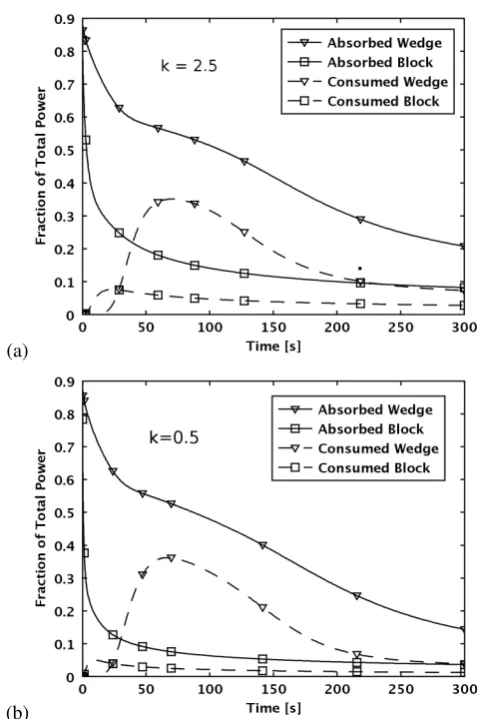
The initial temperature in the simulation was changed from 300 K to 1000 K, to simulate a cycle situation, where the sec-ond step takes place at lower but not ambient temperature. If continuously cycled the material temperature should not drop below 1000 K due to self heating in the water splitting reaction. In Fig. 5 the red curves are for the wedge and the blue are for the solid block. The solid lines are the fraction of the incoming power which is not re-radiated and dashed lines are the frac-tion of the total power consumed by the reacfrac-tion. The energy consumed by the reaction in the case of the wedge is far higher than that of the block. This is due to the larger quantity of the reactive ceramic heated. This reduces the amount of re-radiated heat as it consumes heat, reducing the temperature of the reac-tive ceramic, which can be seen by the bulge that appears in the absorption curve, compared to Fig. 3. This is an excellent im-provement over the case of the block where the large majority of the incoming power is re-radiated and only a small amount of the ceramic is reduced.
It is also notable that when the thermal conductivity is re-duced to
0.5 Wm−2K−1, the reaction efficiency of the block is
approx-imately halved while the performance of the wedge is almost
(a)
[image:5.595.310.549.77.437.2](b)
Figure 5: Total energy absorbed and consumed by the reaction for the wedge and block for two values of thermal conductivity, where the lines marked with triangles are for the wedge and those marked with squares are for the block. The solid lines are the absorption and the dashed lines are the consumed power.
unaffected. This result is promising for the porous ceramics as their thermal conductivity could be very low.
5. Efficient Cavity Receiver Design
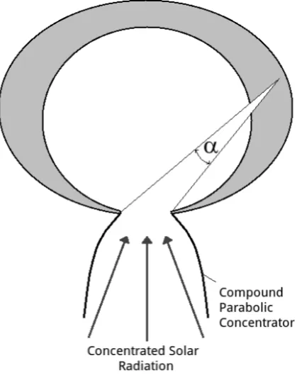
In order to design an efficient cavity receiver we must ensure that radiation received into the cavity is inside the acceptance angle of the wedges. This is not difficult as we can simply set the minimum acceptance angle to be the angle made between the material and the cavity opening. This is shown in Fig. 6 for a cavity using a compound parabolic concentrator, whereαis the minimum acceptance angle for a wedge.
As an example we have simulated a two dimensional cavity receiver with and without wedges. The same reaction equations and material properties as section 4.3 were used. The thermal conductivity was again set to 2.5 Wm−2K−1. The total outside
width of the cavity is 80 cm, the height is 45 cm, and the input aperture is 8 cm. The input power through the aperture was 1500 Wm−2s−1which is equivalent to a concentration of 1500
Figure 6: A cross section of a cavity showing one wedge cut.
the temperature profiles and the power which is absorbed and sonsumed in both cases.
An immediate observation is that the wedge case is far more uniformly heated. This is good as thermal shock will be re-duced which will improve material lifetimes. The wedge case uses roughly double the fraction of the power used as compared to the flat interior cavity. It is however yet to be determined weather this wedge design can have such an improvement for a three dimensional cavity design. The authors leave this for future work.
6. Discussion
The design could be adapted to improve the efficiency of a number of fixed bed reactor designs. In order to fully deter-mine its potential the optical properties of the porous monolith material would need to be determined. If the material acted rea-sonably close to a black body (like Fe3O4) the analysis would
be a reasonably good measure of the materials performance. These simulations illustrate the importance of optimising heat flow to improve reactor efficiencies. In order to improve the efficiency, one needs to increase the yield, reduce radiation loses and exchange the excess heat from the reduction step of the cycle. We see from this that the low thermal conductivity of the porous ceramics is problematic but can be designed around. In our calculations we assumed that the materials were in a vacuum. In the case of a purge gas being used, and provided that P >> Vt
RTf
Ti Cv(T)dT, then the result should not greatly differ. Here Pis the power supplied to the reactor, Vt is the
volumetric flow rate of the purge gas,Tiits initial temperature,
(a)
(b)
Figure 7: (a): Temperature profile of a two dimensional cavity with and without wedges after 15 minutes of heating. (b): Fraction of total power absorbed and consumed over 30 minutes for the two cavities where again the lines marked with triangles denote the cavity with wedges. Solid lines are for absorption and dashed lines for consumption.
Tf its final temperature andCvthe volumetric specific heat
ca-pacity. If the purge gas was flowing from the hot area to the cold area of the monolith it would also improve the heat flow through the ceramic.
7. Conclusions
Our FEM simulations show that cutting wedges into low ther-mal conductivity materials allows larger quantities of the mate-rial to be heated with concentrated solar power and reduces re-radiation losses. For the example used the absorption efficiency was approximately doubled over 300 seconds of heating. This improvement is restricted to cases of low thermal conductivity. The range of values of thermal conductivity for which it offers an improvement increases with increasing incident power. For an input power of 500 Wm−2s−1the wedges improved
absorp-tion when the thermal conductivity was less than 25 W m−2
[image:6.595.308.545.84.463.2]outperforms the block due to multiple reflections of light in the wedge. The design can be scaled up to further improve the radiation absorption performance. When used in a vacuum en-vironment to reduce reactive ceramics the reaction yield and efficiency is significantly improved due to more material being heated and less re-radiation.
Acknowledgments
This work has received funding from SFI-06/IN1/I91, and the International Graduate Research Programme in Micro- & Nano Engineering, an IRCSET graduate research education programme. It was conducted in association with the Cleaner Energy Lab Trinity College Dublin. This article has been published in the International Jour-nal of Hydrogen Energy. It is also available at elsevier -http://www.sciencedirect.com/science/article/pii/S0360319912008518
[1] T. Kodama. High-temperature solar chemistry for converting solar heat to chemical fuels. Progr Energy Combust Sci, 2003;29:567-97. [2] Aldo Steinfeld. Solar thermochemical production of hydrogena review.
Sol Energy, 2005;78:603-15.
[3] S.Z. Baykara. Experimental solar water thermolysis. Int J Hydrogen Energy, 2004;29:1459-69.
[4] Tatsuya Kodama and Nobuyuki Gokon. Thermochemical cycles for high-temperature solar hydrogen production. Chem Rev, 2007;107:4048-77. [5] Stphane Abanades, Patrice Charvin, Gilles Flamant, and Pierre Neveu.
Screening of water-splitting thermochemical cycles potentially attrac-tive for hydrogen production by concentrated solar energy. Energy, 2006;31:2805-22.
[6] Christopher Perkins and Alan W. Weimer. Likely near-term solar-thermal water splitting technologies. Int J Hydrogen Energy, 2004;29:1587-99. [7] Irina Vishnevetsky, Alexander Berman, and Michael Epstein. Features of
solar thermochemical redox cycles for hydrogen production from water as a function of reactants main characteristics. Int J Hydrogen Energy, 2001;36:2817-30.
[8] A. Steinfeld. Solar hydrogen production via a two-step water-splitting thermochemical cycle based on Zn/ZnO redox reactions. Int J Hydrogen Energy, 2002;27:611-19.
[9] Fernando Fresno, Tomoaki Yoshida, Nobuyuki Gokon, Roco Fernndez-Saavedra, and Tatsuya Kodama. Comparative study of the activity of nickel ferrites for solar hydrogen production by two-step thermochemical cycles. Int J Hydrogen Energy, 2010;35:8503-10.
[10] Hiroshi Kaneko, Takao Miura, Akinori Fuse, Hideyuki Ishihara, Shunpei Taku, Hiroaki Fukuzumi, et al. Rotary-type solar reactor for solar hy-drogen production with two-step water splitting process. Energy Fuels, 2007;21:2287-93.
[11] Alex Le Gal and Stphane Abanades. Catalytic investigation of ceria-zirconia solid solutions for solar hydrogen production. Int J Hydrogen Energy, 2011;36:4739-48.
[12] H. Kaneko, T. Kodama, N. Gokon, Y. Tamaura, K. Lovegrove, and A. Luzzi. Decomposition of Zn-ferrite for O2generation by concentrated
solar radiation. Sol Energy, 2004;76:317-22.
[13] Nobuyuki Gokon, Tatsuya Kodama, Nobuki Imaizumi, Jun Umeda, and Taebeom Seo. Ferrite/zirconia-coated foam device prepared by spin coat-ing for solar demonstration of thermochemical water-splittcoat-ing. Int J of Hydrogen Energy, 2001;36:2014-28.
[14] James Miller, Mark Allendorf, Richard Diver, Lindsey Evans, Nathan Siegel, and John Stuecker. Metal oxide composites and structures for ultra-high temperature solar thermochemical cycles. J Mat Sci, 2008;43:4714-28.
[15] T.H. Bauer. A general analytical approach toward the thermal conductiv-ity of porous media. Int J Heat Mass Transfer, 1993;36:4181-91. [16] William C. Chueh, Christoph Falter, Mandy Abbott, Danien Scipio,
Philipp Furler, Sossina M. Haile, et al. High-flux solar-driven thermo-chemical dissociation of CO2 and H2O using nonstoichiometric ceria.
Science, 2010;330:1797-801.
[17] Roland Fortunier Jean-Michel Bergheau. Finite Element Simulation of Heat Transfer. Wiley; 2004.
[18] Micheal W. Glass. Chaparral: A library for solving large enclosure radi-ation heat transfer problems. Technical Report SAND95-2049 UC-700, Sandia National Laboratories, East Lansing, Michigan.
[19] Comsol Multiphysics. Heat transfer user’s guide, version 4.2. 2011. [20] Moungi Gabriel Bawendi Robert J. Silbey, Robert A. Alberty. Physical
chemistry, 4th Ed. Wiley; 2005.