INTRODUCTION 2
THE PRINCIPALS OF PLATING 3
SAFETY PROCEDURES 5
SETTING UP A WORKSHOP 6
AVOIDING TRAPPED GASSES ON WORKPIECE 14
HEATING THE PLATING SOLUTIONS 15
THE POWER SOURCE 20
WIRING UP THE PARTS 29
REPAIRING PITTED METALS 31
CASTING A NEW PART 35
BUFFING AND POLISHING 36
PREPARING YOUR SOLUTIONS 43
INTRODUCTION TO PLATING PROCEDURES 50
METALS CHART 51
BRIGHT ACID TIN PLATING PROCESS 52
REGULAR NICKEL & COPY CHROME PLATING PROCESS 53
NICKEL & COPY CHROME PLATING TROUBLESHOOTING 55
ELECTROLESS NICKEL & KROME PLATING 56
ZINCATE INSTRUCTIONS 65
STAINLESS STEEL ACTIVATOR 66
FLASH COPPER PLATING 67
BRIGHT ACID COPPER PLATING 69
COPPER PLATING TROUBLESHOOTING 70
PLATING PLASTICS & NON CONDUCTIVE MATERIALS 71
BRONZING BABY SHOES 74
PLATING GLASS TABLEWARE 75
GOLD & & SILVERING GLASS 75
CHROME PLATING 77
OPERATING THE NEW DECORATIVE CHROME SYSTEM 80
GENERAL HARD CHROME PLATING INSTRUCTIONS 81
DEVELOPMENT OF HARD CHROME SOLUTION 82
THE PRINCIPLES OF HARD CHROME PLATING 87
PREPARING HARD CHROME SOLUTION 90
HARD CHROME PLATING THE USE OF CONFORMING SHAPED ANODES 93
HARD CHROME PLATING MILLING CUTTERS, DRILLS & FLAT PLATES 98
HARD CHROME PLATING PLATING MULTIPLE PARTS 100
HARD CHROME PLATING MULTIPLE PARTS NON CRITICAL DIMENSIONS 101
HARD CHROME PLATING MULTIPLE PARTS TO CRITICAL DIMENSIONS 105
HARD CHROME PLATING INSIDE DIAMETER PLATING 107
HARD CHROME PLATING DEPOSIT LOCATION CONTROL 110
HARD CHROME PLATING FINISHING 116
INTERRUPTED CHROME PLATING CYCLES 117
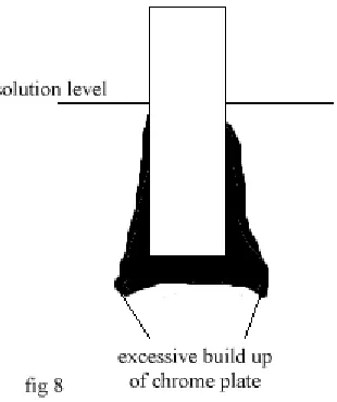
PROCEDURE FOR THE REMOVAL OF CHROME PLATE 118
CHROME PLATING TROUBLESHOOTING 120
ANODIZING ALUMINUM 121
BRUSH PLATING WITH PLUGNPLATE 136
GOLD EMBLEM PLATING USING PLUGNPLATE 138
DIP PLATING WITH PLUGNPLATE 140
RUB ON SILVER PLATING 141
SILVER PLATING KITS 142
24 CT GOLD TANK PLATING 143
FASTGOLD 145
BLACK OXIDIZING OF STEEL 146
COPY CAD & ZINC PLATING INSTRUCTIONS 148
CHROMATE PROCESSES 154
ZINC & COPY CAD BLACKENER 155
ANODIZE & CHROME STRIPPER 156
ANTIQUING OXIDIZERS 158
PLATING LEAD, PEWTER AND STAINED GLASS OBJECTS 159
BRASS TANK PLATING 160
MANUFACTURING GUILDING FOILS 161
WASTE DISPOSAL & EMMISSIONS 162
Introduction
Electroplating is a method of covering objects with a thin layer of metal. Discovered by Michael Faraday in the 1830's it has enjoyed enthusiastic development and application in many areas of industry, and touches our everyday lives in many ways.
This manual and our kits, have been designed to help the smaller operation obtain a professional finish, with fairly basic plating techniques. Of the thousands of different methods and formulae available today, we have chosen several which fit the 'keep it simple' philosophy! The entire manual revolves around our 'electroplating in miniature' systems, no references are made to large commercial set ups, unlike other manuals. These things are deliberately NOT mentioned to avoid confusing you with irrelevant material.
Many of our customers have started off with our kits, mastered the basics of plating, then furthered their education and gone on to set up larger commercial operations. We are happy that they do this, as it is proof positive that they are able to obtain sufficient technical know-how and practical expertise from these smaller operations.
This version of The Complete Plating Manual has many new additions. Its overall format may look similar to the previous edition, but please follow every step carefully, as many procedures have been improved and altered. We have also tried to keep each plating procedure's setup and operating notes together, so you should not need to keep referring back to different sections. There are many new photographs to help you visualize each setup, along with the original CAD drawings and diagrams from version one. Some of the procedures will not apply to you, if you don't have the relevant plating kit. All our chemicals are pre-weighed and mixed, so do not concern yourself with knowledge of chemistry.
We have also taken great care to ensure we are using the safest available routines, but the new plater should, never the less, look to his personal safety as he starts to use these systems, for all chemicals are toxic. Because our systems use such minute quantities of chemicals on such an occasional basis, there are usually no problems concerning government departments. However, please note the new sections that discuss waste disposal and chrome emissions.
Many of the chemicals we incorporate into our systems are ordinary household products, such as bleach, Soft Scrub, Ammonia, Hydrogen Peroxide, and Muriatic acid. You will occasionally be required to purchase some of these materials to supplement the operation of the kits. These chemicals are quite safe, if used correctly, and are not considered dangerous goods. They do not even pose special disposal problems.
The actual process of plating is very simple, and once a kit is set up, a novice plater can experience the pleasure of seeing the plating taking effect within 5 to 10 minutes.
We will provide you with a comprehensive system and a good technical backup service, and you should visit our web page at www.caswellplating.com for updated support. Our policy is to strive for continual improvement in procedures and techniques, which will result in a continual update of this manual. By sticking to our methods rather than the dozens of others out there, we can easily trouble shoot any problems you may encounter.
Our new PRS (Problem Resolution System) is now available on our web page for problem solving of technical issues. Simply log on to www.caswellplating.com, look for ‘support’ then ‘PRS’. Your username is ‘support’, the password is ‘plater’. This system keeps a log of all activities, as we progress through troubleshooting your problems. It is continually being updated, and answered usually two or three times a day. The service is free to bona fida customers. Please see page 166 for further details.
If you have any questions or problems, please let us know. We probably have the answer, and if we do not, we know where to find it!
The Principals of Plating
The Principals of Plating
Electroplating is the depositing of positively charged metal particles (ions) moving through a solution by electricity, attracting them onto an object that has been given a negative charge.
Using the immersion plating technique, the object to be plated (the cathode) is connected to the negative (-) side of the battery, giving it the negative charge, and a metal plate usually made of the plating metal (the anode) is connected to the positive (+) side of the battery, giving it a positive charge.
Positive ions flow from the anode toward the object being plated, through the plating solution (the electrolyte), and are deposited onto the surface of the object. The longer the system is left on, the thicker the resulting plate will be.
Commercial platers usually 'TRIPLE' chrome plate steel in the following manner:-
Strike coat of Cyanide Copper For bonding Acid Copper Plate For hi-build filling
Nickel Plate For the corrosion resistance
Chrome Plate For the color and protection of the nickel
The cyanide strike coat is an inexpensive method of providing a fast bond for the Nickel, but as it is only a very thin layer it has to be built up with the acid copper.
Acid copper can plate layers up to 1/4" thick, given time, and as it is a soft metal, it can be polished to give a beautiful luster. This is the stage where the commercial platers spend their time to get the 'show quality chrome' finish we all know.
The Nickel Plate is the hard protective layer, and is really the 'guts' of a chrome plate. It is this nickel you usually see peeling from an old bumper. As this is a hard metal, it is more difficult to polish or burnish, and so it is essential that all blemishes and repairs are done before this stage.
Nickel, given time and the elements, will dull down, giving a flat almost leaden look. It can often easily be brought back to life with a little chrome polish, but it is for this reason that chrome is applied.
Decorative Chrome plate is a very thin layer of plate. It can be applied directly to many metals, but it is extremely porous and will allow the part to rust through in next to no time. Only by providing adequate under layers of copper and or nickel, will this be avoided.
Our New Triple Chrome Kit offers a set up similar to the commercial plater, except that we use a strike coat of FLASH COPPER instead of the cyanide copper. FLASH COPPER will bond to almost all the same materials that a cyanide copper plate will. The obvious advantage is that FLASH COPPER is much safer.
Our New Triple Chrome Plate Procedure is:-
FLASH COPPER 15 minutes
Acid Copper Plate 15-30 minutes - only if repairs are needed.
Nickel Plate 30-45 minutes Chrome Plate 2 - 4 minutes
Often, a nickel plate can be applied without the underlying copper plates. This will work particularly well on steel.
A simpler and effective alternative to real Chrome plating, is to use Copy Chrome. This can be applied directly to steel, copper, brass and bronze, so it will also go over FLASH COPPER. When more difficult metals such as lead and pot metal need to be plated, FLASH COPPER can be applied as the ‘primer’ and then Copy Chrome applied over.
Brush Plating is a technique which allows you to plate a small area on a part without immersing it in a tank. This is especially useful for doing touch ups, or gold plating, where the solution is expensive.
Electroless Plating is a chemical reaction of the part and the solution, usually heated, which plates the part extremely evenly. This technique is very useful for small parts,
Practice makes Perfect. The best platers keep notes! Recording your successes and failures is the best way of learning, and practice really does make perfect. If it isn't working, you are probably doing something wrong! Check your procedures with the manual and try again. If you can't fathom it out, make a note of what you did and then give us a call. We can usually fix it quickly! We suggest that you start off with some scrap metals for your first efforts. Short lengths of copper pipe are great for practicing on. Save each piece so that you can apply another plate to it when you set up the next tank.
If it isn't working, you are probably doing something wrong! Check your procedures with the manual and try again. If you can't fathom it out, make a note of what you did and then go to our web site and use the PRS support system. We can usually fix your troubles quickly using this system!
Try some different finishes like wire brushing, emery sanding, bead blasting or buffing and polishing. Practice your buffing skills on these bits of pipe, then plate all of them! You will immediately discover the benefits of good preparation, and then understand that 'show quality finishes' have little to do with the actual plating. It's all in the prep
Your first plating job can be plating your tank bars. A good nickel plate applied to these copper pipes will dramatically reduce any corrosion forming on them.
This version of our manual is going to have a notation against different kits, denoting the skill level required. Rated 1= easy , 10 = very difficult
You should start off using ONLY ONE KIT AT A TIME. If, for example, you have a TRIPLE CHROME KIT, don’t set up all the tanks, because you’ll be tempted to flit amongst the processes. It is imperitive that you master ONE SKILL at a time. DO NOT progress to another kit until you are quite satisfied you are producing good plating.
We suggest, that with a Triple Chrome kit, you set up the nickel tank first and learn that process. Once mastered, the other kits will be muich easier to understand.
Safety Procedures
Safety Procedures
The major problem with any larger plating operation is the emission of fumes from the tanks during the plating process. Fortunately, we do not have to deal with this in the same way as the commercial platers, due to our 'miniature' systems.
In the case of nickel, copper, Copy Cad, Copy Chrome and zinc plating, the fumes are hardly noticeable, and do not pose any major health risk. However, the chrome, SP Degreaser and de-plating tanks do give off unpleasant, and potentially dangerous fumes. These need to be considered and controlled.
We suggest you manufacture a small fume hood and/or install a fan system to move the fumes away from yourself. An ideal ready made inexpensive hood is a kitchen stove fume hood. The use of a respirator is also advisable.
Our Chrome kits have a fume control system. This comprises of a bag of plastic balls and an EPA compliant mist suppressant which is mixed into the Chrome Activator.
The plastic balls are placed in the chrome tank, and they float on the surface of the chrome. The Chrome Activator is also added to the tank. The mist suppressant in the Activator is a commercial 'oil' which fills the gap between the balls. The combination of these two items, virtually eliminates all fumes from the tank. The balls also hold the heat in. Additional balls may be purchased for use in the pickling tanks.
The actual chemicals themselves are all toxic! None of our systems contain cyanides. All products have a special set of safety and material safety data sheets. Most of the other chemicals are either acids or alkalis, either type will burn skin and blind eyes if the proper precautions are not taken.
You should use goggles, gloves and an apron while using your plating operation.
Acid Spills
Keep a box of Sodium Bicarbonate (Baking Soda) handy. Sprinkle on the spill to neutralize the acid. Then mop and flush.
Disposal of chemicals (for more details see- Waste Disposal & Emmissions)
Most plating chemicals contain heavy metals. They should not be flushed down drains, even in small quantities. To dispose of chromic acid solution, you may purchase a small Chrome Neutralizer kit from us. Simply add all the contents of the kit to your chromic acid and allow it to work. Then you may pour the solution down the drain. The sludge at the bottom of the tank should be placed into a plastic container and handed in at any 'transfer station' where you would dispose of household paint. Do not 'flush' this sludge. It is a heavy metal.
When you finally dispose of the other chemicals, you should evaporate off as much water as possible, place the remaining sludge in a plastic container, and take it to a 'transfer station', telling them what the chemical is. They will usually dispose of it for you at no charge, considering the small quantity, preferring to do this than let them be flushed!
In the case of spent SP Degreaser this is only a caustic solution and is drain safe, so can be flushed into a sewer system.
Spent acid solutions from the preparation tanks can be used to clean up concrete or neutralized with baking soda. Ask the supplier of these materials for correct disposal procedures.
Some DON'Ts
Don't pour water into any acid, it can heat up and sometimes explode. Pour acid into water.
Don't come in contact with Chromic Acid. It will burn, stain and is a dangerous material if not treated with respect. Don't think you can get away without taking safety precautions! You can't!
Don't leave the lids off your tanks when not in use. They WILL get knocked over!
Material Safety Data Sheets
Setting up your plating workshop
Setting up a Workshop
Although we have shown a complete workshop here, it is NOT necessary to go to these lengths, you can plate from one tank at a time quite easily!
Here is an example of a neat setup, where the entire operation has been enclosed in a home made cabinet. The top has an exhaust system build in, and there are even glass doors to enclose the operation. Note how the tanks are sunk into the worksurface.
Top left hand shows a power supply, which is connected to the bus bars running along the back of the unit. Operating notes/reminders are pinned on the back wall.
Tank heaters are located on the left and right sides when not in use.
As you will be using acids, alkalis, water etc. and doing surface preparation to various metals with grinding and polishing tools, you will be making some mess and a few smells. We recommend you find a place where you can set up that has a good concrete floor, preferably painted with an epoxy, has some cross ventilation and running water. The kitchen is NOT a good idea!
Plenty of workbench area is a must. You might have up to 4 plating tanks set up at any one time, and will need more space to lay objects out etc.
Set your workbench next to a sink if possible, and tilt the bench so it drains into the sink. Minor spills can be flushed away easily. Some of our customers have purchased 'seconds' kitchen work tops as benches. They have even cut holes in them to recess the tanks.
Find a free area for your buffing equipment. This needs to be away from the plating tanks, as the dust and small metals particles dispelled into the air, can settle in the tanks and spoil your solutions. Your buffing machine can be mounted on the edge of a bench with one wheel hanging over the side. This allows the part, if caught, to drop fairly harmlessly we hope, to the floor. Alternatively, you could construct a pole stand and mount the motor on that.
You will need some good lighting for the workshop, as you will need to inspect
your work thoroughly. The area
Setting up your plating workshop
Setting Up A Workbench
Depending on the size of your kit, you need to make a suitable workbench. Ideally, it will be close to a sink and a water supply, and the surface could even be tilted to drain into the sink.
A framework of 2" x 4" timbers, is ideal for most triple chrome plating operations. The 2 & 4 gallon setups could be set at your waist height, but larger tanks would need to lower to make it easier to lift the heavier parts in and out of the tanks.
Customers may install a plywood or Formica type surface. Do not use particle board as the liquids will disintegrate it very rapidly.
The air pump and gang valve are installed on the pegboard (top left) Bus Bars are attached to the pegboard by drilling and bolting. Note:- two bus bars running across pegboard.
The actual work surface should be strong enough to withstand weights of 200 lbs+(16 gallon kits contain about 150 lbs per tank, so build a STRONG framework and place these tanks on top of the work surface). Do not cut the holes too close to the edges of the board. The plating tanks should fit snugly into the cut hole, resting on the lip around the edge. Ensure the fit if fairly tight.
Additional tanks may be stored on the lower shelf
Storing the chemicals when not in use
None of our chemicals are damaged by freezing, however if the tanks freeze they may crack open, and give you a real mess to clear up when they thaw. So we suggest you store them in a heated area. Ensure the lids are secure on each tank and mark the tank with an indelible marker, denoting the contents.
If you intend storing the chromic acid from the chrome plating tank, for a long period, say 2 years or more, we suggest you transfer the product to a glass container. This acid will very slowly attack the plastic tank, and may cause you an unpleasant clean up job.
.
Making a fume hood
For the occasional plater, a fume hood may be an extravagance, and the problems of occasional fumes can be dealt with by simply opening a window and placing a fan by the offending tank, or simply wearing a respirator with acid gas cartridges.
There are a number of options for a fume hood. Normally, hoods will not be necessary for nickel and copper plating, as the fumes generated are very minimal from these processes, but from the greasing, De-plating and Chrome De-plating tanks some sort of control is almost vital.
A simple hood can be made from plywood, and coated with a bituminous or epoxy paint. Or the use of a range hood from a cooking stove could be a 'ready made' solution. The fan motors in these will usually not last too long, as the acid fumes will attack the windings. The best arrangement is to rig up a simple ventura blower, using an air line or a vacuum cleaner exhaust, as pictured above.
Setting up your plating workshop
Make a hole through to an outside wall, or place your exhaust pipe through a window.
Using some 4" plastic pipe make up an arrangement as shown in the diagram.
Make a hole in the bend of the pipe large enough for you to insert your air line or vacuum exhaust pipe.
When the air line/vacuum is switched on the force caused by the ventura principal will suck all the fumes out through the larger pipe. There are no moving parts and the system is therefore fairly foolproof!
Air Scrubber Unit
See the section on Zero Emissions
You may also consider constructing a simple 'scrubber unit' to clean the air from your fume hood. Depending on the size of your operation, you can make this set up from something as small as a 5 gal pail to a 55 gal plastic drum
You will need a small water pump, preferably with an all plastic housing and impeller. The pump is there to circulate water around the tank. As the water is introduced back into the tank it must be made to spray out in all directions as a fine mist. It is this curtain of mist that traps airborne particles of acid, ' scrubbing' the air clean as it passes through the curtain.
Setting up your plating workshop
Bus Bars
You may wish to mount two lengths of 1/2" copper pipe along the back wall of the bench. Space them about 6" apart, and mount them on wooden blocks using the 'u' shaped straps designed for plumbing. These are your 'BUS BARS' and carry the power from your battery to the various tanks. They allow you to connect to a power unit saving a 'spaghetti' mess of wires. Remember to get alligator clips large enough to clip onto the copper pipes.
Paint both ends of the top bar RED, and the bottom bar BLACK. You may like to nickel plate these bars to stop corrosion forming on them. This could be your first plating job.
Note. In the picture left the bottom two bars are the bus bars
The Agitator
During the plating operation a small quantity of hydrogen gas is formed on the work piece. If this is not removed, the plate forms around the bubbles leaving tiny craters. One simple method of removing these is to simply shake the tank bar every few minutes. Agitation also keeps the temperature of the tank even and the chemicals well mixed. The use of compressed air is the conventional method of doing this. Once set up the system can be left unattended.
TO MAKE A SIMPLE AGITATOR.
Cut a length of aquarium air pipe and punch small holes in the last 9" of it. Space them about 1" apart. They should be large enough to let fairly big bubbles through. You do not want a fine mist as this will simply add to the problem. This can be best achieved using a small nail to punch through the plastic.
Cut a length of plastic coated wire about 9" long. Stretch and melt the plastic over the ends, so they are sealed. Insert the wire into the air pipe where you punched the holes. Bend the wire or tie off the end. This gadget can now be dropped into the tank and shaped to suit any work piece. The bubbles should float up around the part, gently agitating it, or at least knocking off the hydrogen bubbles.
Here is a larger tank with a zig zag pipe system across the bottom.
This air agitator can easily be made from ½” pvc plumbing pipe and elbows.
Setting up your plating workshop
Anodes & Cathodes
Supplied in each kit is a set of metal plates which can be either a cathode or an anode. The plates are called anodes when they are used in a plating tank, and cathodes when they are used in a de-plating tank. Anodes are always connected to the (+) positive side of a power unit, and cathodes to the (-) negative side.
The anodes we supply are of very pure quality. Substituting, particularly copper, is tempting but can result in low quality copper being introduced into the bath, which can cause contamination of the solution and disbonding of subsequent layers of plate.
Nickel Anodes 4" x 6"
Nickel anodes are supplied either singly, or in a set of 2, each with a special bandage. The bandages should be wrapped around the anode, to make an envelope and secured with a rubber band. This prevents the oxide that forms during plating from falling into the solution and contaminating it. The other types of anodes do not usually require this treatment. Note how the bottom of the bandage is folded up and then secured. Always remove the anodes from the tank after plating. Rinse and dry them to store.
Copper Anodes 4" x 8" (High Phosporous)
Supplied singly, or in a set of 2, with anode bandage. As of January 1997, we have changed our policy on anode bandages for copper, and they will be added to each pack of anodes. Install the bandages in the same manner previously described for nickel plating. Anode bandages in copper provide a smoother, higher quality plate. Always remove these anodes from the tank after plating. They will deteriorate rapidly if left in the tank.
Pictured right, the anode and bandage, with a strip cut to make the tank hanger.
Chrome Anodes 12" x 12"
These larger plates are used as anodes for chrome plating. The chrome is derived from the solution and not from the anode, so these plates are a permanent fixture. They are a specially made alloy of lead and antimony.
Chromic acid will attack the anode. forming a yellow layer of lead chromate. This acts as
an insulator and prevents the anode from functioning properly. Anodes must be removed from the tank, immediately after plating and cleaned with a Scotchbrite pad in fresh water to remove this film. Dry and store the anode ready for the next usage.
Chrome anodes need to be affixed to a heavier wire than all other types of anode, due to the much larger current requirement of the plating operation. To affix the anode to a thicker wire (such as jumper cables), bare approx. 2" section of the wire and roll a corner of the anode around it. Hammer flat to secure. The anode can be hung into the tank, using the wire as its positioning support. Alternatively, use jumper cable clips to secure the anode to the tank wall and make the connection.
PEROXIDING CHROME ANODES. As an option for chrome anodes, you may wish to treat them to prevent the build-up of ‘lead chromate’ This yellow coating prevents the correct function of the anode. It usually occurs if the anodes are left in the solution for long periods without regular cleaning.
Make up a solution of 15% sulfuric acid (battery acid) and 85% distilled water. Clean the anodes with wire wool, and connect anodes to a dc power supply, one to the negative and one to the positive. Adjust the current to obtain approx 5amps per sq foot of anode surface area. Maintain current for 15 minutes.
Setting up your plating workshop
Finally, reverse the polarity once more, and repeat the process for 15 minutes.
A dark brown coating will form on the anodes, indicating the prescence of lead peroxide. This layer will prevent the formation of the lead chromate whilst still allowing the current to flow.
Installing the anode/cathodes
It is imperitive that you do not allow any connecting wires/clips etc. to be immersed into the plating solution. Any such foreign objects will be dissolved by the plating action, and the result will be a contaminated electrolite.
To ensure that ONLY THE ANODE is dissolved, cut a strip down one side of the anode, about 1/4' in. Do not completely sever the strip from the anode, stop cutting about 1/4" from the end. This strip can now be bent 180 degrees to make the hanger and contact for the anode.
Drop the anode into the solution, and bend the top of the strip over the lip of the tank. You may now use an alligator clip to attach your power line to the anode. Attach a second wire from this anode to any other anodes.
Anode Positioning.
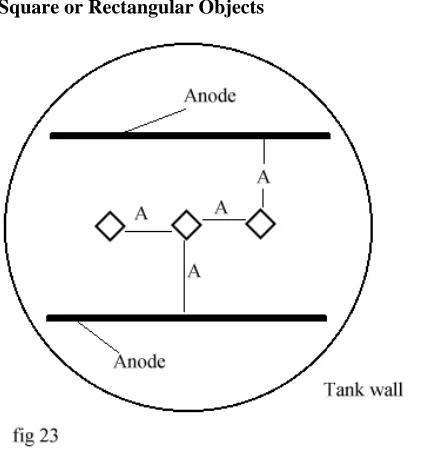
Most items can be plated in our round tanks with an anode either side. In larger round tanks several anodes may have to be placed around the circumference. The effectiveness of an anode placement is something you will learn by experience, but as a general rule, try to keep the anode at least 3" away from the article being plated and no more than 9" away. When chrome plating, remember that chrome has poor throwing power, so anodes should be evenly placed around the object.
For long objects, several anodes may have to be placed along the length of the tank.
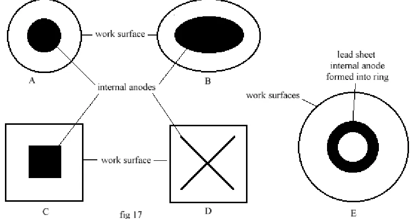
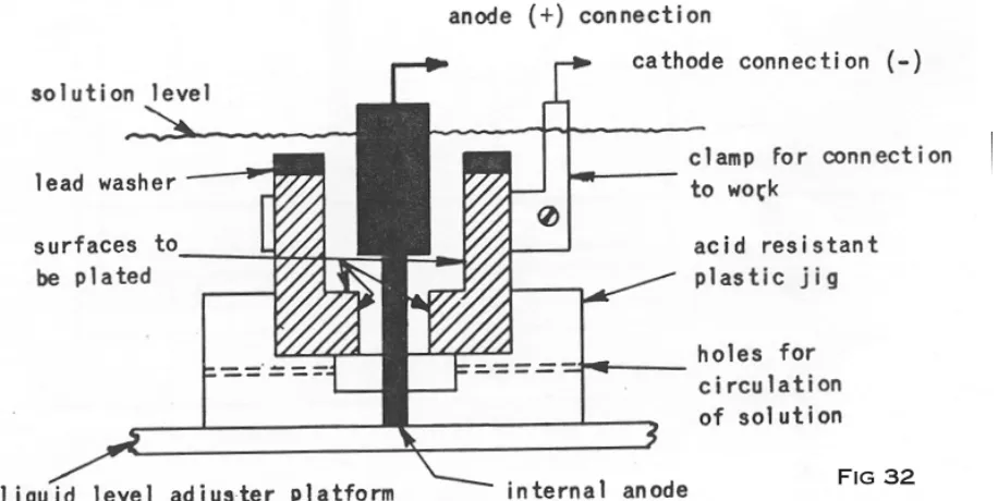
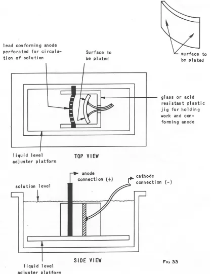
Objects with recesses may not plate effectively in the recessed corners. To overcome this, you may need to place the anode closer to the recess and actually form it to conform to the recess.
To reach difficult areas, you may need to make a cut in an anode edge and bend a strip upwards, so that it can be pointed into the recessed area. This technique is especially useful for plating inside tubes. See the section on HARD CHROME PLATING, for specific anode design.
In the picture, left, a long object is required to be plated on one side only. Both anodes have been placed on one side, facing the part. Their strips are joined together ready for the positive terminal from the power supply to be attached.
If both sides were to be plated, anodes would be placed on either side of the part, which would be centralized in the tank.
Left. The two tanks bars have the part suspended on copper wire. If the part were to be plated on both sides, additional anodes should be placed opposite the existing ones.
Setting up your plating workshop
Here are several configurations of anode placement. Tank C shows the anodes hung centrally in the tank, and bent around to keep their surface equidistant from the part. This is especially useful when chrome plating a small part. If the anodes were left in the A tank position, the distance from the part would be so great that the 'chrome anode would be unable
to 'throw' the power across to the part, resulting in a patchy, or non existant plate. The anodes in tank C could also be made into a complete tube, with the part hung in the center.
The configuration in tank B could be used when the part has many 'nooks and crannies', ensuring the 'Lines of Force' come from many directions.
Here left, the lines of force are shown. Note in A that the areas directly opposite the anodes get more lines of force, so get plated heavier. Whereas the ‘sides’ of the part get much less.
In tank D, note that the lines of force are only attracted to one side of the object, so the side ‘in shadow’ from the anode doesn’t get plated.
GP Plates 8" x 8"( General Purpose Plates) Used for Anodizing, Stripping.
In these instances the plates are called cathodes, and are wired to the negative side of the power unit. They may be attached to wire in exactly the same way as the chrome anodes. If the tank is to be stored for any length of time, it is advisable to remove the anodes/cathodes, wash & dry them and store them separately.
Making up the tanks
There are two basic types of tanks; A. PLATING B. DE-PLATING.
A. PLATING TANKS are used for applying the various metals to the objects. One type of tank will only plate one type of metal, therefore you will have several tanks for triple chrome plating, where the requirement is to copper, nickel then chrome plate. The metal plates used in these tanks to supply the plating metal are wired to the positive side of the power source and are, in this instance, called the ANODES. The part to be plated is wired to the negative side of the battery and is called the CATHODE.
The negative CATHODE attracts metal from the positive ANODE.
B. DE-PLATING TANKS are used for:-1. removing old plate
2. anodizing aluminum 3. dissolving rust 4. electric etching
These tanks are set up in exactly the same way as the plating tanks, except that they are wired up IN REVERSE.
So you end up - DE-PLATING.
Setting up your plating workshop
Plating long objects.
As our tanks are cylindrical in shape, this can cause some problems when plating longer objects. Most objects can be half plated, then turned in the tank and the other half plated. Where there is a join mark, this can be buffed out leaving no signs of its existence. Pictured right is a plastic window box. Note how the anodes are placed on one side only. In this instance, only one side of the object needs plating. More anodes would be needed to plate both sides, or the object could be turned and the process started over for the other side.
THE WORONKO PLATING CHAMBER
This ingenious tank was developed by Mr. Henry Woronko, a customer of ours.
The set up is extremely simple and inexpensive to make, and can plate parts up to 6 feet long, if adapted.
Once the tank is assembled, it should be wrapped in fiberglass, or pipe insulation and covered with plastic sheet to protect it from the splashing chemicals.
Seal it with duct tape. This will keep the temperature constant which is a major consideration when chrome plating.
Increase the solution's recommended temperature by 20 deg. F when using this set up, as the larger and cooler part will drop the temperature as it is introduced to the system. This particularly applies to chrome plate.
All our procedures can be used in the tank, de-plating, anodizing, and all other plates. Ensure you rinse the tank thoroughly between changes! If you chrome plate, make a special tank, specifically for the purpose, and do not use it for any other type of plating, otherwise you will contaminate your solution.
The Woronko Plating Chamber is operated by hanging the long thin part into the fatter area of the chamber, and held there until that section of the piece is plated. As soon as there is sufficient plate, the piece is lowered, so the plated are now drops into the lower, thinner section of the tank. The process is repeated until the entire item is plated. There will be no 'tide marks' or bumps in the plate using this technique. Extra long items could be plated down one half, then turned around and plated from the other end.
MAKING A TANK BAR
Using a hammer, flatten about 1.5" of each end of a 1/2" x 14" copper pipe. On our 1 & 2 gal plating kits, use a 1/4" diameter pipe. On the 16 gal kit, use a 1" pipe. Bend the ends at 90 degrees, so that they fit over the outside edge of the tank. These bars will be used to suspend parts in the tank.
For most applications, simply wrapping the wire from the part around this tank bar several times is sufficient. However, to ensure good electrical contact, you may wish to drill several holes along the length of the pipe and insert some brass bolts & secure with nuts. The part's wire can then be affixed to these bolts and locked into place with another nut.
Keep the bar clean by occasionally scrubbing with wire wool. This ensures a good electrical contact. You may plate the bar with a nickel plate to reduce corrosion. Use these tank bars as your first plating job!
Avoiding Trapped Gasses on Workpiece
Heating the Plating Solutions
Heating the Plating Solutions
Almost all our kits have a heater supplied with them. Depending on the size of the tank, the heater will be either 100 watts, or 300 watts. These heaters have been specially designed to work in our plating tanks.
The heaters are submersible. However, in some of our smaller kits, they may be too large to operate like this, so we suggest that you hang them from the side of the tank. 2 sucker clips are included for this. Alternatively, you may make a loop of plastic coated single strand wire that fits around the neck of the heater and then bend the ends over the tank edge to make a hook.
The glass tube is very fragile. It may break if tapped or dropped. It will also crack if thermally shocked. This can occur when the heater is hot and a quantity of water is added to the tank If the heater is completely immersed, you are unlikely to cause thermal shock to it by adding water to the tank, but if any portion of it is above the water line, then you could damage the glass. It is advisable therefore, to only add water to the tank when the heater is cold. Do not remove the heater when it is hot. Do not place large objects in the tank quickly, as the rise in liquid level may crack the glass.
To further prevent damage to the glass, we have supplied a length of Poly-net to encase the glass tube. Stretch the net over the glass & secure with a twist of plastic coated wire or a plastic tie.
To set the heater adjuster to the optimum temperature of your tank, turn the heater dial to its mid range position and then immerse it into the solution. Monitor the temperature after approx 1 hour, and make adjustments accordingly. If the heater does not bring the temperature up high enough, remove the cover and undo the screw holding the dial. On some models, you'll see a small groove on the underside of the dial. There is a raised nipple on the head of the heater and this runs in the groove. The groove does not go all the way around the dial, stopping you from continually turning the dial to raise the
temperature. You may either lift the dial over this stop, or simply drill out or cut out the stop, allowing free and continual movement of the dial. Most models have already had this modification carried out.
Do NOT swap your heaters from one type of plating tank to another. Small quantities of solution lodge under the dial cap, and this WILL contaminate different solutions.
Heating the Plating Solutions
If you decide not to completely immerse your heater, you may hang it from the edge of the tank by making a wire holder and hook, (see left). This can be adjusted to let the maximum amount of the glass be immersed.
Another way of bringing a tank to its operating temperature quickly, is to remove a saucepan full of liquid and bring it to a near boil on a hotplate, then return it to the tank. Always use a ceramic lined vessel for heating solutions; otherwise, you may contaminate them.
Some solutions work better with high temperature settings, such as SP Degreaser, and often an aquarium heater simply will not bring larger quantities of liquid to the near boil.
By transferring the liquid to a metal can, it can be placed over a gas or electric burner and brought to temperature. If you are using the
liquid with low voltage to strip plating, then you can simply clip the wire to the tank, using the entire metal surface of the container as your anode/cathode.
Heating the Plating Solutions
Insulating the plating tanks.
Simply by taping an insulating material around the side and the bottom of your plating tanks, you can rapidly decrease the amount of time required to warm up the solution from cold, and particularly in the case of chrome plating, attain a higher temperature using only aquarium heaters. However, if you intend to use direct heat, such as a gas burner, then some consideration to the flammability of the insulating material must be given.
There are several suitable materials for this. Many hardware stores sell an aluminum foil combined with a bubble wrap especially for insulating domestic water heaters. It comes in various widths and is very inexpensive.
There are several sizes of 'Bubble Wrap' packaging material available at many 'office supply stores'. Even a layer of corrugated cardboard covered with plastic sheet (to keep it dry) will make a huge difference.
The inclusion of mist control balls to any plating tank, will also hold in the heat. We only ship these with chrome and anodizing kits, so they may need to be ordered separately.
In the picture here, a mist suppressant is also being added.
Double Boiler - an alternative way of heating
The use of the 'double boiler' technique can often be a simple yet fast way of bringing a plating tank solution to a higher temperature than the 'aquarium type' of heaters supplied.
Using any steel vessel as the outer jacket, place a wire trivet or cake stand in inside and drop in the plastic plating tank. Fill the jacket with fresh water, to about 1 or 2 inches below the top. You need to allow some room for bubbling etc.
The plastic tanks do tend to insulate somewhat, so it is advisable to find the thinnest plastic container to increase heating speed. Place a lid on the tank during heating to conserve heat.
Almost any configuration of tank can be designed, with a variety of external heating sources, which can be thermostatically controlled.
Ceramic Lined Tanks.
Heating the Plating Solutions
Heating larger kits
Larger tanks, such as the 16 gal kit, may be heater with commercial quality heater such as the ones shown here.
The section containing the heater may be made of quartz, titanium or stainless steel, depending on which chemical it is heating.
These heaters come with a thermostat control and a probe which is inserted into the solution. They operate on 110 volts.
A typical 16 gal Triple Chrome Plating kit contains:
2 x 1000 watt Titanium Heaters 1 x 1000 watt Quartz Heater with guard 1 x 1000 watt Stainless Heater
Some Things You Might Need
SOME THINGS YOU MIGHT NEED
You will need to collect some articles before you can start plating. We suggest you read the entire book before trying to collect these items, to determine your requirements for each procedure.
For general requirements
-A candy or aquarium thermometer Distilled Water (not mineral water) Rubber gloves (kitchen type, not latex) Goggles
Plastic Apron Alligator clips
Red & black Plastic Coated copper wire.
Stirring sticks, preferably plastic or wood, NOT metal!
Muriatic Acid (or hydrochloric Acid -this is swimming pool or concrete cleaner) 1 gal Swimming Pool water test kit, (for checking pH of your water supply)
Sulfuric Acid (battery acid 1.26 baum)approx. 1/2 gal Acetone or lacquer thinner 1 gal (for oil & grease removal) Bare copper wire, approx. 18g. Heavier gage for Chrome plating. Some spare plastic containers.
Aquarium heater (Supplied with most kits)
14" lengths of 1/2" copper pipe - to make TANK BARS. One for each tank A respirator with ACID GAS cartridges
The Power Source
THE POWER SOURCE
There are many choices of power source, all of them being able to cope well with most applications. All our kits, except Chrome and Copy Cad, will work well from a car battery or a battery charger. Even a cheap 2 amp trickle charger will plate surfaces of up to 30 square inches, which is sufficient for many of the small parts likely to be plated in our operation. If you decide to use a rectifier, you need not be concerned at to how you are going to control the power, as these units have built in rheostats. But, if you want to use a simple control, without the use of these more expensive units, then you will need to control the power with either a rheostat or light bulbs. Please see the section on 'Controlling the Power'.
The 25 amp & 60 amp Rectifier.
Powered by 110 volts, these rectifiers will plate continuously all day long. They are ideal for the smaller workshop with a higher output.
The 25 amp rectifier will plate up to 20 sq. inches of chrome, but will admirably cope with all other plating tank requirements.
We suggest that this machine is your best choice. If you require to plate occasional larger parts with chrome, then set up large batteries and the salt water rheostat system, as this is more cost effective than purchasing the 250 amp rectifier.
The 60 amp machine is capable of plating smaller items with chrome up to approx. 50 sq. inches in total surface area.
The 250 amp Plating Rectifier
This unit will plate chrome parts up to approx 200 sq. inches in surface area. It is not suitable for chrome plating small parts less than 20 square inches, or for any other type of small item plating, because the lower end of the 'tuning' range is simply not fine enough to give you an accurate result. For these parts use the 25 amp rectifier.
The only disadvantage of rectifiers, is their cost. For the occasional plating job, the initial cost may be prohibitive. So, an alternative low cost method is to use light bulbs to control a battery. See the next section on “Controlling the Power”.
The 6 & 12 volt Battery
Giving pure 'ripple free' DC current, these batteries are the obvious preferred choice of power source, and are able to supply high amperage for a short duration, ideal for chroming small parts.
The Power Source
The Battery charger
Often they come with their own ammeter, and a variety of settings. Some of the larger ones will give outputs of up to 300 amps, but the voltage needs to be reduced to plate effectively. On smaller operations, a charger can be effectively controlled using light bulbs, or a salt water rheostat.
The 'ROBBER' principle may also be employed effectively to control the output. (See the section on 'Controlling the Power'.
Here is a typical setup showing charger backing up a battery, ammeter and voltmeter in the correct positions, and a bulb rack which can be replaced with a suitable rhoestat (salt water is an option). The battery & charger can be replaced with a rectifier.
Combining battery & charger for chrome plating
If you are chrome plating larger parts up to approx. 200 square inches, we suggest you use a combination of battery and a larger battery charger. Use a battery with a high cranking amps rating, such as a marine deep cycle trolling battery or a ready made 6 volt battery from a golf cart.
You should couple the charger to the battery and then draw your current from the battery.
Unlike plating other metals, chrome plate will not form unless there is sufficient power. The part will just sit in the tank bubbling away all day until you increase the power.
The Power Source
Power for very small items
We have introduced a new PLUG 'N PLATE power pack to our COPY CAD system
.
This unit supplies 1.5 volts @ 300milli amps (ma). As the requirement for Copy Cad, gold, zinc etc is 1.5 v @ 25 ma per sq. inch of surface area, then this unit will plate up to 12 sq. inches. (It will actually plate up to about 16 sq. inches in practise)
Using the 'ROBBER' technique, see the section 'Controlling the Power', very precise plating can be achieved on smaller articles. This unit is much preferred by us than using small batteries, as the output from these varies tremendously as the battery wears out. However, batteries may still be used, as follows:-
When you are plating very small items, such as a nut & bolt, or a washer, with a zinc, nickel, COPY CAD or copper plate, a smaller control system will be required. As bulbs, rheostats and most rectifier units will not reduce the current from a six or 12 volt battery sufficiently, you can use a simple flashlight 1.5 volt battery as your source. You can connect the battery directly to the anode without a bulb or resistor in the circuit. We have found that an AA type battery will plate an item up to 5 square inches in surface area beautifully with any of the systems mentioned above. If you have a very small article, use an older ' flat' battery. If the color of the plate is dark, then use a smaller, flatter, battery. This is a great way of using up those old batteries!
The Arc Welder
This is not our preferred choice of power unit, never the less it will work well providing you make some following modifications. Most arc welders supply 24 volts output and very high amperages, the latter being ideal for chrome plating. However, this voltage is generally too high, and needs to be reduced.
By setting a 2:1 step down transformer in the line between the main 120 volt circuit and the charger, you will drop the input voltage to 60 volts. Therefore the output voltage will be 12 volts, a more acceptable figure for our purpose. We suggest you control the current at the source because it is more economical to get a mains step down transformer, than a 24 volt, 300 amp setup.
Alternatively, if you have a 220 volt Arc Welder, this can be wired to a 110 volt supply, which will reduce the output by half.
Consult a qualified electrician for this work.
This system can produce dangerous currents to the tank, if the modification is incorrectly carried out.
The Power Source
Controlling the Power
If you are using a Rectifier, controlling the power will be a straightforward job of dialing up the amount required, depending on the size of the part to b e plated, and the amperage requirement. For example, nickel requires 1 amp per 15 square inches of surface area. So, a 45 sq. in. piece will need - 3 amps.
If you are using a battery or battery charger as your power supply, these units have no power control, and if you were to hook them up directly to the part and the anodes, plating would be fast and furious as the as the current virtually shorts across the tank. Of course, you would probably ruin the part too! To control this power, (to 'slow' it up) we have to place some resistance in the line. This can be done by using either light bulbs, or a rheostat. Whilst the bulbs may look a little amateurish, they really do an excellent job of plating, and should not be underestimated! If you decide on obtaining a rheostat, we have provided OHM's law below, to enable you to work out the resistance YOU require. We cannot do this for you here, because we don't know what you are plating. If you have any difficulty in doing this, get in touch with us and we'll be pleased to help.
For controlling large currents, as used in Chrome Plating, you may wish to use the Salt Water Rheostat (See this section). It is an economical unit to construct and is very reliable.
Most applications will use a 6 volt supply.
Choosing the right bulb
You will use different size bulbs depending on the surface area of the part to be plated.
You need to consider the size of the largest part you are likely to plate when you construct your bulb rack. If you are only plating an odd item, you may not even want to bother with making a rack, just simply plug in a bulb and place the bulb holder into the circuit.
These 6 volt bulbs & sockets may be obtained from any motorcycle outlet, lawnmower repair, golfcart repair, & Radio Shack.
6 volt 100 ma bulb RADIO SHACK product # 272-1142
6 volt 250 ma bulb RADIO SHACK product # 272-1130
Threaded Bulb Base RADIO SHACK product # 272-360 Or # 272-357
Most of our plating tanks, except chrome, zinc & Copy Cad, draw roughly the same amount of amperage, 1 amp plates approx. 16 sq. in.
Here are two bulbs manufactured by United States Hardware Manufacturing Inc. Washington, Pa 15301
1. Product # RV 371B 12 volts 15 watts = 1.25 amps 2 Product # RV373B 12 volts 50 watts = 4 amps
The Power Source
Here is the setup for a typical bulb control system. There is no need to use an ammeter, because you already know the current draw from the bulb rating.
To increase the amount of current, simply add more bulbs
As an example, say we wanted to plate 90 sq inches of nickel. Nickel requires 1 amp per 15 or 16 sq inches. Therefore 90/15 = 6 amps.
This larger current could be obtained by using 24 x 250 ma bulbs, or by going to a 12 volt system and using 6 a 4 amp RV bulbs. Don’t forget that you can use either 12 volt or 6 volt power supplies, but the bulbs must be rated for the same voltage.
Chrome plate draws 1 amp per square inch of surface area, which is much more than the other processes.
As an example, lets imagine you were plating 24 sq inches of surface area. Then you would need to place 6 x 4 amp bulbs into the circuit.
For a better understanding of this procedure, go to www.caswellplating.com/flash/bulbcontrol.swf
There are many combinations of bulbs that can be used.
You could add many more larger bulbs to control even a chrome plating operation.
Check the bulb rating, and remember that amps = watts/volts
So, as long as you have the voltage and the wattage of the bulb, its pretty easy to calculate how much power it will draw.
eg: 12 volt bulb rated 15 watts = 12/15 = 1.25 amps
The Power Source
Making a bulb holder
A bulb holder rack can be made from any small box, wooden or plastic. Radio Shack sell some inexpensive boxes ideal for this purpose.
Once you have determined the maximum size of part you are likely to plate, you can then obtain the necessary amount of bulb holders.
Use single filament bulbs & sockets wherever possible, as this is easier to set up. If you are electronically inclined, you will soon understand how to wire up double filament bulbs in parallel, thus saving on bulbs.
Mount the sockets in the box and solder a connecting wire to each bulb socket casing linking them all together. Run this wire to a bolt mounted on the box. This is your power terminal A
Join all the wires together and mount them on a bolt which is secured to the box. This is your other power terminal B. To test the box, connect both terminals to your battery and plug in the bulbs. They should all light brightly.
Making a salt water rheostat
A simple rheostat can be an excellent inexpensive addition to a miniature plating workshop. The following design works well for controlling 10 amps -100+ amps.
Obtain a suitable plastic container as a tank, approx. 10" x 15" x 10" deep.
Cut 2 sheets of copper.
galvanized sheet metal, brass or lead to fit on one side of the tank. The thickness of the sheet is not important, so long as it is fairly rigid.
Attach a piece of wooden batten to the top edge of both pieces of metal with screws. The batten should be long enough to rest across the tank top, so as to suspend the plate into the liquid.
Attach a wire to each sheet, making sure you have a good electrical connection. One wire from one plate should connect to the positive side of your battery, the other to the anodes.
You may fix one plate to the side of the tank so that it does not move. Also secure a large piece of plastic rain gutter mesh. This will stop the two plates touching each other and shorting out.
The Power Source
longer to heat, or by cooling the water by a simple heat exchanger made from a coil of garden hose placed in the bottom of the tank, with cold water running through it
To operate:-Fill the tank with fresh water. Pour in approx. 1 pound of salt, and stir to dissolve. You may alter the concentration of salt to achieve different results. By adding more salt you will increase the amperage range.
Experiment to obtain the range you require.
Slide the moveable plate to alter the resistance. The further apart the two plates are the less current flow will occur. If you discover during your operation, you do not have enough resistance from the salt water rheostat, simply remove some of the salt water and replace with fresh, thus decreasing the conductivity.
In the picture, left, lead sheet has been used for the plates. This has been wrapped over a short length of copper tubing. The tank is a plastic window box.
During continual use, the water temperature in the tank may rise and this will effect the resistance. You may have to make an occasional adjustment to maintain the same setting during long plating episodes with high amperages.
Controlling the Power From a PLUG 'n PLATE Power Pack Or any a/c adapter
To best demonstrate the 'robber' principal, we are going to use thePlugNPlate kit instructions. Of course, you could use a battery charger, providing you know the amperage output, and adapt this method to almost any other situation. Most parts requiring plating with COPY CAD are fairly small, so this power pack is designed to provide enough power to plate up to 15 sq. inches of surface area.
The output of the Power Pack is 300 ma (milli amps). The requirement for Copy Cad plating is 25 ma per square inch. Therefore, this unit will plate 300/25 = 12 sq. ". (In practice, it will actually plate a little more, about 15 sq. inches)
If the part to be plated were exactly 12 sq. inches, then it would simply be placed into the plating tank and connected to the negative Power Pack connector. The Anode would be connected to the positive connector, and plating would commence. The 300ma output would match the surface area, and no further adjustment would be necessary.
However, not all parts are going to be exactly 12 sq. inches, so we must 'rob' some of the power from the Power Pack. This is achieved by placing more surface area in the tank to be plated. As the output from the Power Pack is constant, we must adjust the surface area being plated to match the output. Too much current on the work piece will result in a dark, rough plate, and too little current will give us a patchy plate.
The Power Source
1. Add more parts to be plated, until you have 12 sq. inch total surface area.
2. Add a 'ROBBER' to the parts to be plated.
You may use almost anything that has a surface area of 7 sq. inches, but that would be somewhat wasteful, so, a simple robber needs to be made from part of the anode supplied with the kit.
Cut a strip from the long side of the anode, which is 1" wide, and mark it off in 1 inch increments. This 'ROBBER' has a total surface area of 16 sq. inches.
Place the ROBBER into the Plating solution, so that 3.5" is immersed. (That gives you a total immersed surface area of 7 sq. inches) and then bend the ROBBER over the tank bar, ensuring it has good electrical contact. Now, you have 5sq" of part to , and 7sq" of ROBBER, making a total of 12 sq", so you should achieve optimum plating capability. The ROBBER may be used late as an anode, so no product is wasted.
Calculating Electrical values (For those who are technically inclined)
OHM'S LAW
This law expresses the relation in an active electric circuit of current, voltage and resistance. These three factors are always present in such a circuit. Its general statement is as follows:
"In an active electric circuit, the Amperes are equal to the voltage divided by the resistance"
In other words:-
1. The Amperes are equal to the volts divided by the resistance A=V/R
2. The Volts are equal to the Amperes multiplied by the resistance V=AxR
3. The Resistance is equal to the Volts divided by the Amperes R=V/A
4. The Amperage varies directly with the Volts and inversely with the Resistance.
5. The Resistance varies directly with the Volts and inversely with the Amperage.
6. The Volts vary directly with the Amperage and with the Resistance.
Resistance = Ohms = R
This law is the fundamental principle in most electric calculations., so, as long as you know 2 figures in the above equations, you can easily work out the third figure.
WATTS
The power value or Watt is calculated by multiplying the AMPS by the VOLTS:-
W = AxV
or V = W/A
or A = W/V
6 volts x 100 amps = 600 watts
,
100 volts x 6 amps = 600 watts,
12 volts x 100 amps = 1200 watts or 600 watts divided by 100 amps = 6 voltsetcA FINAL WORD ABOUT POWER
The Power Source
The battery (or power supply, such as a rectifier) is our reservoir. The deeper the reservoir, the more pressure we have at the bottom of the reservoir (where we draw off the water) The water pressure is VOLTAGE in our electrical circuit.
Imagine we have a huge pipe, say 4 feet diameter, at the bottom of our reservoir, and we leave it open. It wouldn't take too long to empty that reservoir. In the case of the battery, if we had a very fat wire, such as a jumper cable, it wouldn't take too long to empty the battery if we 'opened' (or grounded) that wire.
Now imagine we have a 1/2" open pipe from our reservoir and we leave just that one open. Its going to take a LONG time for that reservoir to empty. This is a thin wire. Too much pressure from the reservoir can actually burst this pipe, (or melt your thin wire)
In the first example, we need a fair amount of that pressure, but we don't need the volume of water (flow or amps), so we need to place a valve in the line. If the valve is adjustable, we now have a 'rheostat' and we can control exactly how much water we let down the pipe.
Experience tells us that certain types of plating need specific voltages and amperages to plate nicely, so it is extremely important to control these flows of current.
There are two thing to consider; is the pipe strong enough, and do we have the right valve (or rheostat) to correctly control the current?
Wiring up the Parts
Wiring Up the Parts
Brass wire is probably the best to use, but is more difficult to obtain. It does not oxidize as quickly as copper or steel. We have always used copper wire with no adverse effects, 10-20 gauge wire is ideal. For chrome plating use a fairly heavy gauge, and/or double it up, as this procedure uses high amperage, which may melt a thinner wire.
Do NOT use steel wire - or copper coated steel wire - it will NOT conduct properly!
When ANODISING, only use ALUMINUM or TITANIUM wire from the tank bar to the part. The wire needs to be SECURELY fixed to the part, otherwise it receives an insulating coat of anodize and then no longer conducts, so the part will not receive any more power, and the process ceases.
Each part needs to be carefully examined to find a suitable place where a wire can be attached, so that it may be hung from the tank bar. There is a good possibility that every place a wire touches the part, the plating process will leave a mark. So, if there is an underside it will always be better to fix to this.
Wire the part so that only the edges are touched, bending the wire away from flat surfaces. Alternatively, parts can be suspended from hooks made from wire, so only the point of the hook is touching the part. (See diagram).
Running wires through an existing hole will often eliminate wire marks.
Another technique is to frequently move the wire to another location; i.e., spin the part, so that the touch point is lessened to any particular point.
Occasionally it will be inevitable that you leave an odd wire mark. This can usually be buffed out with a little care.
Some small parts can be strung on a wire with plastic beads separating them, and then plated all at the same time. Other small parts such as screws or bolts can be fixed into holes drilled into a thin sheet of brass, copper or steel and plated as one, or fixed on to a piece of expanded metal, see below).
If only the heads of bolts require plating, screw them into a metal sheet and immerse just the heads in the liquid. Alternatively, you
could wrap a wire around the thread and then suspend each bolt from the tank bar into the solution, so that just the head is immersed.
Wiring up the Parts
For some hollow objects, where the inside will not get plated, you can use a spring clip (figured below) to hold and connect the part whilst it is being plated.
When chrome plating, you will need to make these wires from very thick single strand wire, and may even need to run several wires to the one object to ensure enough current is conducted. With these stiffer single strand wires, you can make hooks that will hang from the tank bar. By stripping the insulation from only the ends, you can make hooks that do no get clogged up with plating, and may be used over.
All fastenings to the parts need to be secure, especially when dealing with higher currents and in processes such as Chrome plating and Anodizing.
Which ever method you use, make sure you roughly calculate the total surface area of all the parts, and adjust your current controls (bulbs or rheostats) accordingly.
Estimating Plate Thickness
The section of wire that is immersed into the solution can be used as a good indicator of the thickness of the applied plate. Simply measure the wire thickness before plating commences and again afterwards, using a micrometer.
Hydrogen and Air Entrapment
You should give some consideration to the problem of trapped bubbles when
Repairing Pitted Metals
Repairing Pitted Metals
Steel, Copper, Brass. Bronze, Nickel
First, the part must be thoroughly cleaned, preferably by bead blasting and/or electrostripping to remove rust. If the surface has very minor pitting (orange peel texture) then this can usually be filled using a copper plate. Important - On steel, don't forget to prime the steel with nickel or Flash Copper first.
The use of copper plate to repair pits
Apply theBright Acid copper plate, and then flat down with a fine wet & dry paper using a sanding block. Repeat the process until the pits are completely filled with copper. Then buff and polish and finish with a nickel and/or chrome plate. (see below)
If the pits cannot be filled with copper, use a paste grade solder paint, which can be applied with a brush to the surface prior to heating. This allows a thin layer of solder to be applied making the application of larger quantities of stick solder easier, if required, for filling deeper pits. Steel, copper, brass, and nickel can all be repaired this way.
After any soldering soak the part in hot SP Degreaser to remove any flux.
Filling shallow pits & scratches using copper plating
This technique is ideal for a substrate with many shallow pits of approx. 1/16" depth.
The pitted part should be first plated with a 'strike coat' of Flash Copper (1) for approx. 15 minutes. This layer of nickel is not effected by acid and ensures the part is completely protected from the acidic copper solution.
A heavy layer of copper is applied (2), usually for at least 30 minutes. Periodic checks should be made to ensure the plate is smooth. If not, remove and sand lightly, taking care not to damage the Flash Copper 'strike' coat. If your part is pot metal and you do sand through to the pot metal, you will have to 'strike' coat the part again with Flash Copper Alternatively, you could 'touch up' this area using the BRUSH PLATING technique. Flash Copper solutions will brush plate, as long as you use a copper wand.
Once a heavy layer is applied, this can be sanded smooth (3). We have found that it is easier to apply the plate in several layers, sanding lightly between layers. This ensures the copper is removed from the high spots, and left in the pits.
A final layer of copper is applied (4), and then buffed lightly to a high polish. Do not get the part too hot during buffing, or you may make the plate blister.
Finally, the part is returned to the nickel plating bath and plated for 15 minutes (5). The part may be chrome plated immediately after this nickel plate.
Filling pits using solder
Apply a 15 minute 'strike' coat of Flash Copper, then a 15 minute plate with Bright Acid copper .
Repairing Pitted Metals
iron. The area must be heated sufficiently to allow the solder to flow into the hole, yet not hot enough to make the copper plate disbond. Fortunately, Plumb-Loy melts much easier than stick solder, but the could also be used in many situations.
Finally, sand down the solder, ensuring you do not go through the Flash Copper 'strike' coat, and Bright acid copper, then nickel plate directly over. Ensure that you return the part to the degreasing bath to remove flux before the final plate.
The Repair and Replating of Pot Metal (or Zinc Die Casting)
Pot Metal is probably one of the worst things to repair and replate. The metal varies tremendously in its consistency, the foundry seemingly blending whatever metals (usually zinc and a little aluminum) they had available on the day. This, coupled with the fact that the zinc corrodes quickly when exposed to the elements, can make the product seem almost impossible to repair.
Pot metal has always been a major problem for the average restorer to repair, as it can't be welded, brazed or soldered with conventional materials..
Commercial platers use a cyanide copper 'strike' coat then plate with acid copper. The cyanide is, of course, a product that many don't wish to handle. So, the only route has been to send pot metal parts out to a professional restorer, usually at great expense.
UNTIL NOW!!! Because FLASH COPPER substitutes cyanide copper systems, doing exactly the same thing but without the dangers. Now you can plate directly onto metals such as pot metal, pewter, lead and steel with copper. For more information, see the section on FLASH COPPER.
Zinc is a poor choice for a casting. It is readily attacked by acidic situations, as can easily be demonstrated by dropping an eye dropper droplet of battery acid on a cleaned area of a casting. The zinc will start to 'fizz' & bubble' as the zinc is destroyed. Aluminum does not do this, so this is a good way of testing for Pot Metal.
On first examination, an old pot metal part that has been chrome plated will have the characteristic blistering all over it. It would appear that if these blisters were sanded down, the part would be in a good enough condition to replate, but, unfortunately, this is often not the case. These tiny blisters in the chrome plate are just the tip of the iceberg, for when they are examined closely with a magnifying glass, one can see quite deep holes filled with corrosion. This corrosion grows with a tremendous force, pushing the plate from the surface and forming the blisters.
There are many reasons why pot metal corrodes in this way. Poor initial surface preparation. Contaminants in the actual metal. Thin plating being porous and letting the elements through to attack the zinc. The casting itself seems to be porous, holding in moisture like a sponge.
In old pot metal, the corrosion that forms a hole in one area effects the surrounding, seemingly good, area of the metal, making it difficult to plate.
1. Pitted surface
2. Copper Plate (nickel strike if steel)
3. Sanded down
4.
Solder, then more copperRepairing Pitted Metals
The best way to deal with these defective areas is to bead blast the surface, then inspect it thoroughly for dark spots in the pits. These dark areas are oxides formed by the corrosion. The must be removed. Either re-blast the part, or get a small drill and gently drill out the corrosion until you find bare, clean metal. On no account proceed to plating until this problem has been resolved.
Now you have a choice of repair options.
You can use Pot Metal Solder and make repairs to the bigger holes , or
you can plate with FLASH COPPER, the n BRIGHT ACID COPPER, then use Plumloy solder, and then overcoat with FLASH COPPER. You will need to make a determination of which method you prefer depending on your own skill levels.
Preparing the surface
Pot metal has many impurities in it, and the older it gets the worse the part can become. Many castings are porous and absorb water. This can cause many problems during repair, especially during soldering.
Pre-repair heat treatment
In order that the part be cleansed of these impurities and any possible moisture, it should be placed in an oven and baked as
follows:-15 mins @ follows:-150 deg F this gradual increase eliminates any warping/stress etc. 15 mins @ 300 deg F
15 mins @ 450 deg F
At this higher temperature you will find that SOLDER-IT pot metal solder will fuse to the surface easily. A blow torch may be needed to heat the part a little more. Let the heat travel to the solder, do not directly torch the solder as you will burn off the flux and it won't stick properly.
If the repairs are extensive, you may wish to hang the already hot part over a hot plate while you work on it. If you allow it to cool too much, no amount of localized blow torch heat will bring the part up to the correct temperature and you risk damaging the part.
If the part has deep pitting it is usually best to drill out the entire area, ensuring that the corrosion is completely removed. If any is left it will cause a black streak in the plate. This procedure can be likened to drilling and filling a tooth, only less painful! A Dremel tool is ideal for t