A compact shock-assisted free-piston driver for impulse facilities
M.A. Kendall, R.G. Morgan, P.A. Jacobs
Department of Mechanical Engineering, The University of Queensland, Brisbane 4072, Australia Received 7 September 1996 / Accepted 5 October 1996
Abstract. A free-piston driver that employs entropy-raising shock processes with diaphragm rupture has been constructed, which promises significant theoretical advantages over isen-tropic compression. Results from a range of conditions with helium and argon driver gases are reported. Significant per-formance gains were achieved in some test cases. Heat losses are shown to have a strong effect on driver processes. Mea-surements compare well with predictions from a quasi-one-dimensional numerical code.
Key words:Free-piston driver, Impulse facility, Shock waves, Heat transfer, Hypervelocity flow
1 Introduction
A common driver technique for shock tubes is the free-piston compressor as described by Stalker (1972). Although these compressors have proven to be versatile, driver gas pressure and temperature are determined (and limited) by the volu-metric compression ratio. At The University of Queensland, a project is underway to construct a large superorbital expansion tube called X3. The intended diameter of the tube is 180 mm and, in order to generate quality test flows of the order of 15 km/s, the driver needs to generate a hot driver gas slug 1 metre in length, with temperature and pressure of the or-der of 6000 K and 200 MPa respectively (Morgan 1992). This gives a test section total flow enthalpy of 200 MJ/kg. When applied to such high enthalpy applications, quasi-isentropic drivers can become large and very expensive. For example, a free-piston driver for X3 would need to be at least 100 m long. To achieve comparable performance with a smaller (and less expensive) compressor, alternative driver techniques have been explored. In particular, compression processes which in-volve entropy-raising mechanisms were investigated. Theoret-ically, such a process would produce a given temperature rise with a smaller volumetric compression ratio than an isentropic compression alone. Entropy-raising drivers using heat addi-tion, detonations, shocks and throttling processes have been developed with some success, and were considered as driver options for X3. It appeared that a concept first proposed by
Correspondence to: M.A. Kendall
Bogdanoff (1990) which cascaded entropy-raising expansions with quasi-isentropic free-piston compressions was simple and attractive. Thus for the present study a pilot facility was con-structed to experimentally demonstrate the concept. The aims of the investigation were to:
(i) achieve a higher final driver temperature than that can be produced from an adiabatic free-piston compressor of a matched volumetric compression ratio;
(ii) measure and quantify the importance of convection losses;
(iii) investigate practical operational issues, and; (iv) compare results with numerical predictions.
The pilot facility was a modification of a pre-existing expan-sion tube X1 (Neely and Morgan 1994), in which the free-piston compression stage was extended to include the first section of the shock tube. With a diaphragm stationed at the beginning of this extension, the new compression process in-cluded both the quasi-isentropic (free-piston) and entropy-raising shock components.
In the following sections, experimental results from this demonstration are presented together with a description of flow processes involved. It is shown that heat transfer losses were an important factor in reducing driver performance, and, also that the choice of driver gas has a strong influence on convective heat transfer. To complement the experimental results, selected pressure and heat transfer data are compared with simulation data from a quasi-one-dimensional Lagrangian code.
2 Process description
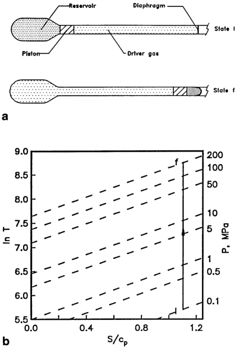
Fig. 1a.A conventional free-piston compressorban entropy map for an isentropic free-piston compressor
proposed for driver enhancement. Modifications to this base process are then considered in order to raise the entropy of the gas during the compression process.
2.1 Effect of an entropy increase
The role of a change in entropy can be seen from the following thermodynamic relations
T T0
=λγ−1
exp (∆S
Cp)
(1)
P P0
=λγ
exp (∆S
Cp)
(2)
where λis the volumetric compression ratio, γ is the ratio of specific heats and,P andT are pressure and temperature respectively. Subscript “0” designates initial conditions. Note that if entropy remains constant, then relations (1) and (2) apply to an isentopic process, which ideally approximates an adia-batic free-piston compression (Stalker 1972) and, for which pressure and temperature are coupled.
It is clear that when the∆S/Cpterm in Eqs. (1) and (2) is manipulated, pressure and temperature are decoupled. Fur-thermore, if driver gas entropy can be increased, then a higher
temperature may be reached for a fixed volumetric compres-sion ratio. This also means the same speed of sound could be achieved with a smaller geometry. Ideally, for the X3 expan-sion tube reductions in size of the order of 5 are desirable, equating to∆S/Cp = 0.65. Thus, the target length for the compact (entropy-raising) driver is 20–30 m.
2.2 Methods of raising entropy
Some techniques that have been applied to raise driver gas en-tropy are discussed with a focus on their suitability in meeting the X3 driver requirements. These methods are:
(i) heat addition (preheating);
(ii) combustion heating (deflagration and/or detonation); (iii) shock heating with high speed pistons;
(iv) shock heating and throttling expansions; (v) throttling expansions, and;
(vi) shock-assisted free-piston driver.
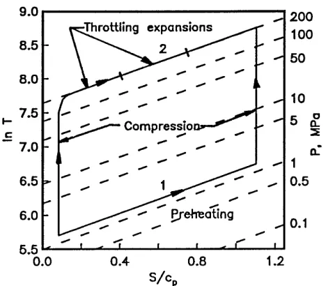
Preheating has commonly been applied to increase the speed of sound of the driver gas in many static “cold” drivers. Driver temperature can be increased by external resistance heating, internal resistive heating or arc discharges. Typically, external heating increases the driver gas temperature to about 500 K, such as in the Calspan and Aachen shock tunnels. However, these temperature changes are well below those required for X3. If external heating is applied to a free-piston compres-sor before piston release, a higher final temperature would be achieved than from a conventional compressor. However, in order to reach a temperature of 6000 K with a volumet-ric compression ratio of 20, the driver gas would need to be heated to more than 800 K before piston release. The process is approximated by line 1 in Fig. 2. Preheating to these temper-atures would result in complications from thermal expansion in the driver walls and piston, and metallurgical effects which would significantly degrade the integrity of the driven tube.
An alternative form of increasing the driver gas speed of sound is through combustion of a hydrogen-oxygen mixture. This technique has been successfully employed in various low enthalpy (≈25 MJ/kg) shock tunnels and tubes. It has been demonstrated by Bakos and Erdos (1995) that the process is not as capable as a conventional free-piston compressor. A pressure limit of 40 MPa (due to chemical effects) and lower sound speeds due to heavy combustion products were cited as the main performance limitations.
Fig. 2.Process diagram for a preheated (line 1) and throttling (line 2) entropy-raising mechanisms applied to a free-piston compressor similar to meet X3 requirements. Conditionsλ=20, final temperature 6000 K, final pressure 200 MPa
Gun tunnels have improved driver performance signifi-cantly in air through shocks generated from high speed pistons (Bray 1962). These facilities are limited by piston velocities (≈600 m/s) and the structural inability of the light piston to withstand high peak pressures and shock loads. Recent work by Terao and Tomonobu (1994) with a heavier free-piston ac-celerated in an evacuated cavity before impacting the driver gas at speed shows promise in overcoming pressure limita-tions. Nevertheless, to maintain a gas seal, piston velocity is still limited to less than≈ 600 m/s. This is well below the 4500 m/s needed in X3 generate the desired entropy change over the primary shock.
Shock heating and throttling may be combined, as in the case of a Bypass Piston Tube (BPP) studied by Kn¨o¨os (1969). The BPP uses shock heating from the sudden expansion of a diaphragm to preheat the driver gas, and set the piston into motion. As the piston enters the bypass channel, the driver gas expands past it, to be conventionally recompressed until diaphragm rupture. If it is assumed that most of the entropy change occurs over the primary shock, a shock mach number of 6.2 is required. To achieve this, large quantities of ambient temperature helium would be needed in the reservoir (pressure greater than 20 MPa). Such a process would be expensive to difficult to operate, as it would require a specially shaped piston for each specific condition.
By superimposing adiabatic compression processes with controlled throttling processes into a succession of chambers, driver performance may also be improved. By using this com-bination of processes in the Russian PGU units, Anfimov (1992) showed that a theoretical temperature increase by a factor of 1.67 in helium (γ) is possible. This corresponds to
∆S/Cp = 0.51 and means that, if losses are not considered, at least two expansion stages are required for the concept to achieve the desired performance in X3. The process is
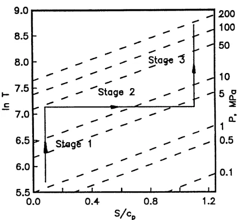
de-Fig. 3.Geometry and typical space-time diagram of an shock-assisted free-piston driver with one diaphragm inserted
noted as line 2 in Fig. 2. Overall, the concept is complicated and would be more attractive if it did not rely on specialized high-speed valves.
Finally, a concept cascading free-piston compression with entropy-raising expansions, first proposed by Bogdanoff (1990), appears to be the simple and attractive in theory. Thus it was chosen to be the focus of the current study. A description of the concept and its theoretical potential follows. From this point on, the term “entropy-raising driver” and “shock-assisted driver” will be used interchangeably to describe the same con-cept.
2.3 Description of the entropy-raising driver
Physically, the entropy-raising driver is similar to a conven-tional free-piston driver, with the addition of (at least) one di-aphragm within the enclosed driver volume. Consider the sim-plest geometry: a single diaphragm mounted midway within the driver. A schematic of this driver with a typical space-time diagram describing its process is shown in Fig. 3. Prior to a shot, volume V0 is filled with the driver gas, while V1
is evacuated (state 0). The process begins with release of the piston (att0), compressing the gas inV0similarly to
conven-tional adiabatic piston compressor, until the rupture pressure of diaphragmD1is reached. Upon diaphragm rupture, the gas
expands into the cavity (V1) to be processed by entropy-raising
shocks. Meanwhile, the already hot gas is quasi-isentropically recompressed to the rupture pressure of the final diaphragm (D2).
[image:3.612.304.548.49.286.2]simplifica-Table 1.Specifications of the pilot driver
L1 L2 λ D Vres T4 T3 T2 T1 P1
[image:4.612.42.287.116.342.2](mm) (mm) (mm) (m3) (mm) (mm) (mm) (mm) (mm) 2340 1020 27 38.1 0.018 340 590 690 790 998
Fig. 4.Ideal entropy versus temperature process diagram for a typical shock-assisted free-piston driver
tion came through modelling diaphragm rupture as a throttling process. By doing this, the following assumptions were made:
(i) entropy-raising shocks occurring over a finite time are replaced by a bulk property change that occurs instanta-neously;
(ii) heat losses are negligible, i.e. the gas expansion is isen-thalpic;
(iii) piston motion is negligible during diaphragm rupture and the instantaneous change of state, and;
(iv) work needed to rupture diaphragms is negligible.
With these assumptions in mind, a simple model for the ex-pected entropy change due to diaphragm rupture was devel-oped. A thermodynamic relationship for a entropy change due to changes in temperature and pressure is,
S2−S1=cpln (T 2
T1
)−Rln (P2
P1
). (3)
where the state before and after diaphragm rupture are des-ignated by subscripts 1 and 2 respectively. Equation (3) and the first law of thermodynamics were applied to the change in entropy induced by a change in control volume seen by diaphragm rupture. In the isenthalpic process temperature is constant, while pressure drops. Furthermore, the drop in pres-sure was inversely proportional to the change in volume
P2
P1
= (V1
V2
). (4)
Manipulation of isentropic, perfect gas and entropy relations yields the entropy rise as a function of the “instantaneous” volume change at diaphragm rupture as
exp (∆S
cp ) = ( V1
V2
). (5)
The modelled ideal shock-assisted driver for a typical geome-try is shown in Fig. 4. Note the distinct compression, expansion and recompression stages. This was in contrast to the actual process, where for a finite time, entropy-raising shock pro-cesses were occurring while recompression was taking place. By combining (3) with normal shock relations,
∆S
cp =
1
γln (
2γM2−(γ−1)
γ+ 1 )−ln (
(γ+ 1)M2
(γ−1)M2+ 2) (6)
was achieved, where it was clear that the higher the shock Mach number (M), the greater the entropy change.
This model was only applied to cases with an evacuated cavity in the downstream driver section. Valid operating con-ditions also had a gas initially downstream of the inserted di-aphragm (D1). These conditions are discussed in Sect. 5.2.
3 Apparatus
The test bed for this driver study was the X1 superorbital ex-pansion tube at The University of Queensland, Fig. 5. The original driver geometry was modified to include a diaphragm (D1) in a constant area tube arrangement.
Figure 6 outlines features of the pilot entropy-raising driver arrangement. Note that the driver is split into two sections, separated by a diaphragm.
Locations of the pressure transducer (P1) and four
ther-mocouples are shown. Driver dimensions and gauge locations relative to diaphragm D1are summarized in Table 1.
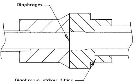
The piston had a mass of 1.08 kg and traversed a tube of a 38 mm bore. A critical event in driver operation was when the piston passed ruptured diaphragm. To ensure a trouble-free interaction for the piston and tube components some unusual design features were incorporated. The diaphragm striker fit-ting was “flared out” to a larger bore Fig. 7. This allowed the piston to safely pass the ruptured diaphragm.
Fig. 5.The X1 superorbital expansion tube
Fig. 6.Schematic of the pilot entropy raising driver 4 Numerical model
Simulations of the driver operation were undertaken in order to help identify the detailed mechanisms affecting driver perfor-mance. In particular, conditions behind the entropy-producing shocks and its cumulative effect on heat transfer and perfor-mance were of interest. The code would also be useful in fea-sibility studies for drivers on larger facilities, such as X3. The numerical modelling of the facility was based on the quasi-one-dimensional Lagrangian gas-dynamic code described by Jacobs (1994). The facility was divided into its component parts such a tube, piston, diaphragms and slugs of gas. Each slug of gas is further divided into a number of control-mass el-ements which were allowed to move along the tube and, at the ends of the slug, push against the piston and/or diaphragms. Only flow in one dimension was allowed and changes in the tube cross-sectional area were assumed to be gradual. This is a considerable deviation from the actual tube geometry which has a couple of abrupt changes in cross section (at the reservoir and buffer) but the error introduced was controlled by sharpen-ing the area changes and increassharpen-ing the resolution of gas-slug discretisation to bring the area changes across individual cells back to acceptable levels.
The core of the simulation was a time-stepping loop which first applies specified boundary conditions and then advances the state of the facility components (i.e. gas-cell positions, pressures and velocities; piston position and velocity; di-aphragm status) in small time steps. During each time step, the gas properties within each (Lagrangian) control-mass cell were updated by considering the conservation of mass, mo-mentum and energy with the interactions between cells being resolved via an approximate Riemann solver. A limitation of
Fig. 7.Diaphragm striker fitting for upstream diaphragm D1, flared out to allow the piston to pass
Fig. 8.Piston used in experiments
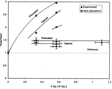
[image:5.612.304.527.342.478.2] [image:5.612.304.472.533.669.2]Fig. 9.Final driver temperatures achieved with helium in comparison with ideal (no heat losses) calculations
even between adjacent cells within each slug. Such mixing can be important in situations where a very low-pressure driven gas (such as in the evacuated cavity) is being shock-compressed by the driver gas.
The effect of the wall boundary layer was included as a shear stress in the momentum equation and a heat flux term in the energy equation. When evaluating these viscous effects, the flow within the cell was assumed to be fully-developed pipe flow and standard engineering correlations for the fric-tion factor are used. Even for the very short durafric-tion flows considered here, this fully developed pipe flow approximation seems to perform adequately.
5 The Experiment
5.1 Measuring driver performance
Driver performance was gauged by the mean final gas temper-ature. Temperature was calculated by manipulating the perfect gas law to
T = PrVr
mgasR
(7)
where gas mass (mgas) was determined from the known initial
pressures and volumes. Rupture pressure (Pr) was measured with a PCB 109A pressure transducer, with a manufacturers quoted rise time of 1µs and sensitivity of 98kPa/mV. Calibra-tion tests found that accuracy was within the specified 2%. The gauge was recessed, and mounted immediately upstream of diaphragmD2(P1). Volume at rupture was obtained through
gradually modifying shot conditions up to the point where the piston came to rest at the buffer as the final diaphragm (D2)
ruptured.
Heat flux to the wall of the downstream section of the driver (V2, in Fig. 6) was determined by integrating temperature
sig-nals from co-axial chromel-alumel (type K) thermocouples. The data was time averaged over 0.1 ms to reduce noise be-fore integration. The thermocouples were recessed 0.1 mm and also useful in monitoring the piston trajectory.
Finally, the measured data was compared with simulations produced from the quasi-one-dimensional Lagrangian com-puter code discussed in Sect. 4.
5.2 Operating Conditions
The conditions tested were categorised as:
(i) quasi-isentropic reference (or base); (ii) evacuated entropy-raising;
(iii) tailored entropy-raising, and; (iv) other entropy-raising conditions.
Quasi-isentropic reference conditions were established by op-erating the driver as a “standard” free-piston compressor with-out diaphragm D1. For all conditions, the diaphragm in the D2
location was 1.0 mm thick aluminium sheet, which ruptured at approximately 15.8 MPa. Performance of shock-assisted con-ditions was determined through comparison with the standard driver.
Table 2. Diaphragm materials and hydrostatic diaphragm rupture pressures forD1location
Material Diameter Thickness ∆Pstatic ∆Pdynamic
(mm) (mm) (MPa) (MPa)
Polycarbonate 43.5 0.38 1.60 1.80
Aluminium 43.5 0.60 4.70 5.2
Aluminium 43.5 1.00 8.03 9.0
Aluminium 33.5 1.00 – 15.8
Mild steel 43.5 0.60 15.75 17.5
Aluminium, steel and polycarbonate diaphragms provided a sufficient range of rupture pressures at the D1 location and
corresponding theoretical entropy changes. Measured hydro-static rupture pressures and the calculated dynamic range (us-ing the strain-based technique described by Jenkins and Gur-genci (1993)) are summarised in Table 2.
For a given shock strength within the driver a theoretical entropy change was expected. Heat transfer from the shock heated gas to the driver walls reduced this entropy increase. To help examine the interplay between these effects, shots were performed with gases with different heat transfer coefficients: helium and argon.
A series of tests were conducted with diaphragm D1
ruptur-ing into an evacuated cavity, which accordruptur-ing to the analytical model (Sect. 2. 3) would induce the greatest entropy change. In these conditions, driver section 2 was flushed with the driver gas and pumped down below 65 Pa.
Another condition was achieved by varying the fill pres-sure of the downstream section of the driver to tailor the shock generated uponD1rupture, so that the speed of sound on
ei-ther side of the interface was matched. Tailoring of the gas within the driver gives improved theoretical uniforimity than the evacuated conditions. However, the Mach number of the tailored conditions has been lowered, resulting in smaller en-tropy changes.
One condition that had a fill pressure in-between the tai-lored and evacuated values was tested. The purpose of this over-tailored condition was to help examine the sensitivity of tailoring on performance.
5.3 Results
The piston successfully passed through ruptured diaphragms for over 80 shots, indicating that the driver components worked reasonably well. Damage to piston rings was little more than usual wear from contact with the tube wall. When the piston passed through a steel diaphragm, wear was more pronounced with some score marks on the piston chevron seal ring.
Gasdynamic experimental results are summarised in Table 3, with notation from Fig. 6. Final conditions (the point of di-aphragm rupture) are denoted by subscript “f”. Conditions 1–4 are characterised by a helium driver gas, with the conventional quasi-isentropic configuration being tested as condition 1. In the remainder of the tests the driver was filled with argon.
Consider the final temperatures achieved in Helium, which are compared with the ideally calculated temperatures (using
the theory from Sect. 2. 3) in Fig. 9. On the vertical axis, the final temperature is normalised by the quasi-isentropic refer-ence, while the horizontal scale is the upstream diaphragm rup-ture pressure divided by the downstream value. Labelled are the shock-assisted evacuated and tailored conditions. Note that all experimental shock-assisted temperatures barely deviated from the reference baseline, indicating that no real tempera-ture increases were achieved. In two cases performance was reduced slightly. These values are well below ideal tempera-ture increases of up to≈250%. This is presumably a result of enhanced heat transfer, as discussed in the following sec-tion. Furthermore, the ideal performance difference between evacuated and tailored cases of 33% was reduced to 13% in the experiments.
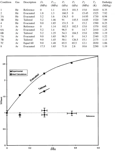
In contrast, significant final temperature increases of be-tween 30% and 50% were achieved with an argon driver gas, Fig. 10. The highest temperature increase of 50% was achieved in an evacuated condition withD1/D2= 0.57 (condition 6A,
Table 3), which was equivalent to the temperature that would be achieved from a conventional driver if it was about double the present volumetric compression ratio.
With the exception of the performance gains achieved with argon, there were many similarities between the argon and helium shock-assisted results. Firstly, there was a large de-parture between the results and the ideal calculations. For example, in the case with a maximum temperature increase (50%), a 200% increase was ideally modelled. Moreover, as the upstream diaphragm pressure (and ideal final temperatures) were increased, experimental temperatures remained reason-ably constant. For example, when the upstream diaphragm rup-ture pressure was increased from 9 MPa to 17.5 MPa (changing
D1/D2from 0.57 to 1.11), analytically modelled temperatures
increased by 40% while experimental temperatures marginally decreased. It seems reasonable to assume that ifD1 was
in-creased further, the trend would continue. This indicates that for the geometry and pressures tested, performance limits were reached with both helium and argon driver gases.
5.4 Analysis of bulk-energy properties
It was clearly demonstrated in the results that actual tempera-ture increases were much lower than those calculated with the ideal theory. Therefore, the loss mechanisms that cause these differences need to be identified and quantified.
The magnitude of driver losses are quantified through an energy analysis. Consider a mole of gas as the control mass within the driver, Fig. 11. Energy is entering the system in the form of work done by the piston (w). Energy leaves the system predominantly as heat (q), diaphragm work (Dw) and piston friction (Fp), before diaphragm rupture. The final driver tem-peratureTf (see Table 3), is linked with the energy exchange by
Tf−T0= γ−
1
R (w−wL), (8)
Table 3.Summary of experimental results
Condition Gas Description D1 Pres P1 P2 Pf Tf Enthalpy
(MPa) (MPa) (kPa) (kPa) (MPa) (K) (MJ/kg)
1 He Reference 0 1.1 101.5 101.5 15.0 1610 8.35
2 He Evacuated 1.8 1.3 160.5 0 15.45 1525 7.92
3A He Evacuated 5.2 1.6 136.5 0 14.95 1730 8.98
3B He Tailored 5.2 1.46 91 145.5 14.85 1520 7.89
4 He Evacuated 9.0 1.85 151.5 0 15.2 1590 8.25
5 Ar Reference 0 1.14 102.5 102.5 15.0 1570 0.82
6A Ar Evacuated 5.2 1.4 96.5 0 14.7 2410 1.25
6B Ar Tailored 5.2 1.25 54.3 104.5 15.0 2290 1.19
7A Ar Evacuated 9.0 1.65 96.5 0 14.3 2340 1.22
7B Ar Tailored 9.0 1.45 50.1 126.5 15.1 2175 1.13
7C Ar Equal fill 9.0 1.48 65.5 65.5 12.1 2030 1.06
8 Ar Evacuated 17.5 1.65 71.8 2.8 10.6 2290 1.19
Fig. 10.Final driver temperatures achieved with argon in comparison with ideal (no heat losses) calculations there are no losses, temperature change is a function of work
andγonly i.e. it would be the same for both helium and argon driver gases.
Total losses within the driver for the experiments, and their effect on temperature increases are illustrated in Fig. 12. Each point is labelled by its experimental condition. Work (w) was approximated by an unsteady expansion of the reservior gas. The ideal case of no losses is represented by the line through the origin. The vertical distances between the data and the ideal line indicates the temperature drop due to driver losses. Small-est losses were seen with both reference conditions, while the
greatest amout of energy leaving the driver occured in the ar-gon condition with the highest amout of work (condition 8). The references exhibited the closest agreement between he-lium and argon driver gases, with losses being of a similar magnitude. For the other (shock-heated) conditions, however, for a given amount of work, losses were lower with an argon driver gas.
Fig. 11.Energy interaction for the driver gas
Fig. 12.The effect of total losses on temperature change within the driver. The line through the origin is the ideal case (no losses)
q=w−R∆T
γ−1−(Dw+Fp), (9)
[image:9.612.305.551.47.232.2]whereFpwas the estimated force required to move the piston at constant speed. The work required to rupture a diaphragm (Dw) was estimated from diaphragm strain and mean driver gas pressure. Convection was found to be the dominant loss term, accounting for 65%–85% of the overall losses. Values of total heat out of the system using (9) for the experiments are plotted in Fig. 13. Note that lowest heat losses occured in the references, while losses were greater for the shock-assisted conditions. Furthermore, for a given amount of work, losses were greater in helium.
Fig. 13.Heat out of the system for the experimental results 5.5 Analysis of mechanisms
It has been established that convective heat losses were largely responsible for the lower than ideal performance. In this sec-tion, the mechanisms behind these losses are investigated with a focus on explaining the experimental results.
5.5.1 Reference conditions
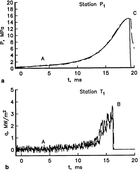
Consider the reference quasi-isentropic conditions for helium and argon. Figure 14 shows samples of experimentally mea-sured pressure and heat transfer histories within the driver (P1
andT1 respectively) for the helium and argon references. A
dashed line is used for the histories with argon. Time t = 0 is an arbitrary origin, approximating 20 ms before rupture of di-aphragmD2. The heat flux history is terminated by the piston
passingT1 at point B, while point C in the pressure history
denotes diaphragmD2rupture.
Note the good quantititative agreement between the ref-erences in pressure and heat flux. It is difficult to discern be-tween the profiles, particularly with the heat flux history. Heat losses were negligible until about 10 ms before diaphragm rupture, where they increased until reaching a maximum of ≈ 3.5 MW/m2 before the piston passed the thermocouple gauge.
Within the experiment, the mode of heat transfer was con-vection to the driver wall, which was governed by the textbook relation
q=h(T−Tw), (10)
whereTwis the wall temperature and the heat transfer coeffi-cient (h) is
h=ρ cp|u|St. (11)
[image:9.612.47.280.169.536.2]Fig. 14a,b.Comparison of pressureaand heat fluxbhistories for the helium and argon (dashed line) adiabatic references
velocities, temperatures and densities result in negligible con-vection to the walls throughout most of the piston stroke. It is only in the final≈10 ms that gas temperatures have increased enough to register significant heat transfer measurements. Fur-thermore, it is not surprising that heat losses in Fig. 14, and the reference in Fig. 11 similar, considering that velocities and temperatures are almost matched throughout compression.
5.5.2 Evacuated shock-assisted conditions
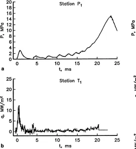
The shock-assisted conditions introduced shock mechanisms within the driver that are clearly seen in a typical evacuated condition. Figure 15 shows pressure and heat flux histories at stations P1and T1for a run with a helium driver gas rupturing
a 5.2 MPa diaphragm into an evacuated cavity (condition 3A in Table 3). Timet = 0 denotes arrival of the primary shock generated by the upstream diaphragm rupture at station T1.
Note the pressure oscillations generated by the shock in-teractions at station P1. These waves were visible until the final
5 ms before diaphragm rupture where the profile approached that measured in the reference history (Fig. 14). A maximum heat flux of≈24 MW/m2was measured behind the primary
shock, which was followed by a similar heat flux level immedi-ately behind the reflected shock. The following spikes indicate subsequent shock reflections.
[image:10.612.299.546.50.350.2]Heat flux behind the first few shocks was far greater than the reference measurements. The resons behind this are seen by inspection of the state of the gas immediately behind the ≈6 km/s shock, with the high gas velocity (≈4500 m/s) and
Fig. 15.A measured pressureaand heat fluxbhistories for a sample evacuated helium condition, condition 3A
total temperature culminating in enhanced convection. Heat transfer levels remain high behind the reflected shock due to the higher temperatures and pressures in the stagnant region. These losses were enough to cancel out any desired entropy increases induced by incident and reflected shocks.
As indicated in the results and bulk energy analysis (Sect. 5. 4), heat losses with an argon driver gas were lower, resulting in overall driver gas temperature increases. These findings are reinforced by a sample of measured pressure and heat flux his-tories for an evacuated run with D1= 5.2 MPa (condition 6A
in Table 3), Fig. 16. The longer period between oscillations in the pressure history indicates slower shocks than those mea-sured in the helium sample (Fig. 15(a)), as expected. Peaks of ≈12.5 MW/m2 were recorded behind both the primary and
reflected shocks, representing a decrease in heat flux by a fac-tor of 2. The driving facfac-tor behind these lower losses is the lower velocities for similar Mach numbers, giving a smaller heat transfer coefficent than that for argon.
5.5.3 Tailored conditions
A similar exchange between heat losses and entropy changes existed with the tailored conditions. Consider sample pressure and heat flux histories for a tailored condition with an argon driver gas rupturing diaphragm D1of 5.2 MPa (condition 6B,
Fig. 16.A measured pressureaand heat fluxbhistories for a sample evacuated argon condition, condition 3A
comparison. Agreement between numerical calculations for the sample tailored results and measurements in Fig. 17 are good. Both the amplitude and frequency of the shocks are modelled well. Similar comparisons were also achieved with the references and other tailored conditions. It was difficult to accurately model the evacuated conditions numerically due to large pressure ratios over diaphragm D1.
Maximum measured heat flux levels of≈5 MW/m2were lower than the peak measured heat transfer in the evacuated condition (Fig. 16). This is due to reduced convective heat transfer from the gas processed by the lower Mach number primary shock.
With these reduced losses, however, the outright perfor-mance for the condition was slightly lower than that measured in the evacuated condition. This is due to the smaller entropy increases sought after with the lower Mach number shock. A similar trend exists between evacuated and tailored conditions with helium as a driver gas.
6 Conclusions
It has been demonstrated on a pilot facility that the perfor-mance of a conventional free-piston driver can be enhanced through the inclusion of entropy-raising shock processes.
Shocks with high Mach numbers are required for large en-tropy changes. The stronger the shock, however, the greater the velocity of the gas behind it. Shear generated from this gas moving parallel to the wall culminates in increased convection.
Fig. 17.Comparison of measured and numerically modelled pressure and heat flux histories for an argon condition (6B). The numerical heat flux calculations are offset for clarity
[image:11.612.45.315.48.344.2]pro-cessed gas. Temperature gains of up to 50% were achieved with argon. Any entropy changes in helium, however, were offset by greater losses.
It is believed that the fundamental problem of heat transfer can be partially mitigated by through geometrical and pressure scaling. New configurations might be worth investigating e.g. radial cylindrical shocks with velocity vectors normal to the wall to eliminate shear and reduce heat losses to conduction.
The analytical approach that models the expansion into an evacuated cavity as an isenthalpic throttling process is invalid. If a correction term is developed for heat transfer, the model may be applied.
It was also shown that a quasi-one-dimensional computa-tional code, with viscous effects is suitable in the modelling of tailored entropy-raising driver conditions. With the use of the code, the capabilities of the driver concept can be explored further through a parametric study and scaling.
References
Anfimov N (1992) TSNIIMASH capabilities for aerogasdynamical and thermal testing hypersonic vehicles, AIAA 92-3962 Bakos RJ, Erdos JI (1995) Options for enhancement of the
perfor-mance of shock-expansion tubes and tunnels, AIAA 95-0799
Bray KNC (1962) Evaluation of the hypersonc gun tunnel, Riddell FR (ed) Hypersonic Flow and Research: 547-579
Cain TM (1986) Compression ignition driven shock tubes, Master’s thesis, Mech Eng Dep The University of Queensland, Brisbane, Australia
Bogdanoff D (1990) Improvements of pump tubes for gas guns and shock tube drivers, J AIAA 28(3): 483-491
Jacobs PA (1994) Quasi-one-dimensional modelling of a free-piston shock tunnel, J AIAA 32(1): 137-145
Jenkins DM, Gurgenic H (1993) The relationship between static and dynamic burst pressures of sheet steel diaphragms, Dynamic Loading in Manufacturing and Service, The Institute of Engi-neers Australia Melbourne Australia: 25-31
Kn¨o¨os S (1969) Study of a bypasses piston shock tube, In 7th Inter-national Shock Tube Symposium
Morgan RG(1992) A compound free-piston driver for expansion tun-nels, In 11th Australian Fluid Mechanics Conference, Hobert, Tasmania
Neely AJ, Morgan RG (1994) The superorbital expansion tube con-cept, experiment and analysis, The Aeronautical J:97-105 Stalker RJ (1972) Development of a hypervelocity wind tunnel,
Aero-nautical 3-34
Terao K, Tomonobu F (1994) Shock tube using free piston driver by detonation waves, Japan Journal of Applied Physics 33:2811 Yu HR (1992) Gaseous detonation driver for a shock tunnel, Shock